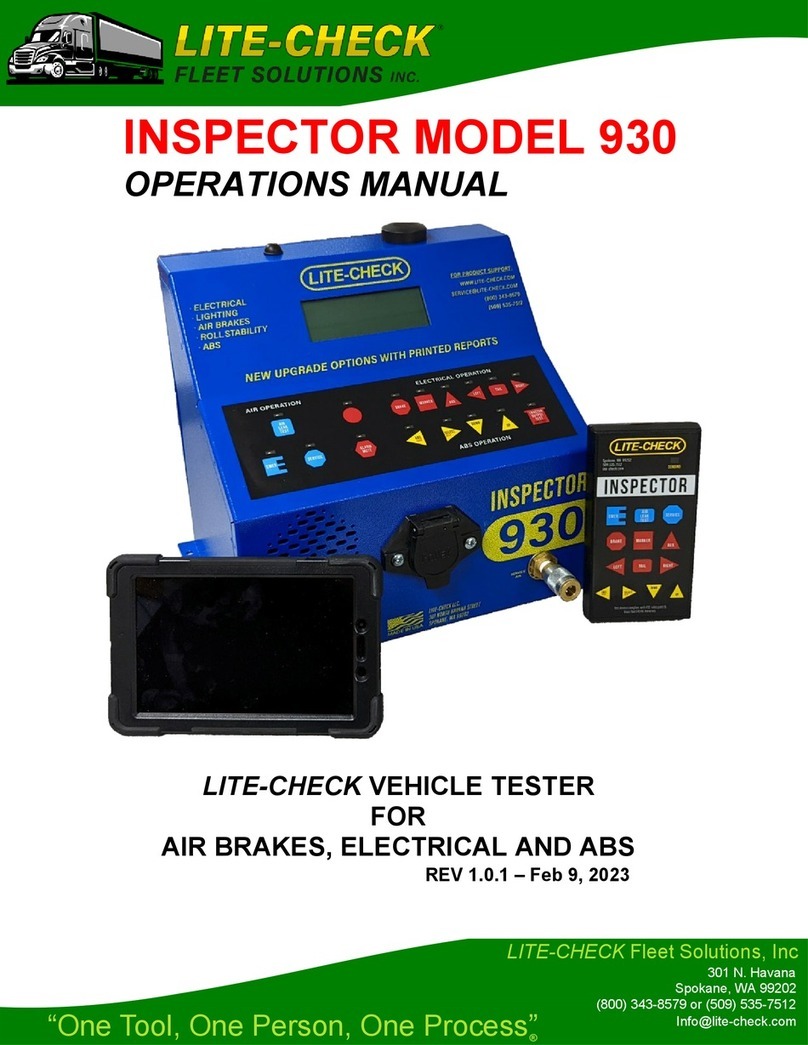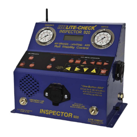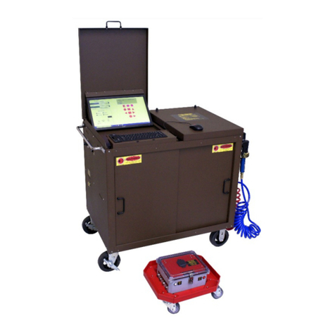
OPERATING INSTRUCTIONS
1. Connect tester to a power source: a 12 volt battery for the PC720, and a
120v AC supply (wall socket) for the PC720AC
2. Connect tester to trailer with 7-way electrical cable
3. Turn on tester - Initial display screen will identify tester, and the second
screen will show the voltage available to the trailer (a minimum of 11
volts is required)
NORMAL OPERATION: Active diagnostics for all circuits
Only one electrical circuit can be activated at a time. Digital Display will show
the circuit, voltage, amperage, and circuit condition.
The PRO-CHECK will automatically identify circuit faults and sound an alarm.
If the circuit fault is corrected, the alarm will cease and display message will
change.
FAULT MESSAGES- The specific fault and all of the circuits involved are
identified
ALARMS - Distinct sound for each type of fault. Alarm will automatically cease
or change as the electrical condition of the trailer changes.
ALL CIRCUIT TEST: Automated diagnostic test of all circuits
Top display row identifies circuit(s): Brake, Tail, Auxiliary, Left, Marker, Right
Bottom row shows circuit conditions: Pass, Open, Short, Chassis, Ground Open
ALL CIRCUIT LOAD: All circuits are made active
Total current draw is displayed
Individual circuits may be turned on and off
CIRCUIT CONDITION DESCRIPTIONS:
PASS - (CIRCUIT PASSES): Digital display will show the current draw (amperage)
on the active circuit
GROUND OPEN - (OPEN GROUND WIRE AND NO CURRENT DRAW): Digital
display shows active/defective circuits and the fault alarm is sounding.
SHORT - (CIRCUIT WIRES ARE IN CONTACT): Digital display shows primary
circuit with connected circuit and the fault alarm is sounding. Amperage shows
the total circuit load on the Digital Display.
CHASSIS GROUND - (CIRCUIT WIRE IS IN CONTACT WITH CHASSIS): Digital
display shows primary circuit with fault message and the fault alarm is
sounding.
Remote Control Operation:
1. Press selected key - momentarily
2. Only one light/electrical circuit will be activated at a time
3. Each remote control is keyed to a specific tester. (Set to serial number)
4. Remote and tester panel buttons have the same operation
5. Range with good AA batteries is over 100 feet
6. Sending lamp will light up when button is pressed on remote control
Note: Replace (4) AA batteries if lamp does not illuminate or if range is short.
CAUTION: DO NOT WELD WITH TESTER CONNECTED TO TRAILER
ABS Test Process
The LITE-CHECK PRO-CHECK 720 is designed to simplify the identification of ABS
related issues. ABS manufacturers have discovered that more than 70% of the
ECU’s returned under warranty actually function properly.
The majority of ABS malfunctions are sensor related
A significant number of non-operating ECU’s result from power issues
The PRO-CHECK method is a 3-step process:
Test Brake Circuit
Test Auxiliary Circuit
Read BLINK code for ABS faults.
The brake & auxiliary circuit test will automatically identify circuit faults such as
opens, shorts, open ground, and chassis ground.
1. Test brake and auxiliary circuits
a. Circuit faults must be corrected
2. Observe the trailer ABS warning light operation
a. Repair if lamp does not turn on
b. ABS lamp stays on indicating an ABS fault
3. ECU valves will chatter during the power up phase
4. No chatter may suggest non-functioning valves
5. If all above is functioning with the ABS warning lamp on, proceed with the
blink code process
ABS Blink Code Diagnostics for trailer ABS
To read blink codes, press the panel LOAD key followed by the ABS type process.
The blink code process is very time sensitive exciting the circuits.
Exciting the ABS by pressing the AUX and BRAKE keys can be done with the remote
control.
Bendix - MC-30 and TAB-6
1. Provide constant power to the ignition (AUX) circuit.
2. Toggle the brake light circuit (3) times
**Wait until after the modulator chuff test before activating the brake light power
**Toggling of brake circuit must be shorter than 5 second intervals
Meritor Wabco
1. Turn the ignition (AUX) switch ON for no longer than 5 seconds. *The ABS
indicator lamp will be on
2. Turn the ignition (AUX) switch OFF. *ABS indicator lamp will go OFF
3. Turn the ignition (AUX) ON. *ABS indicator lamp will turn ON, then OFF
4. The blink code will be displayed three times by the ABS lamp.
HALDEX
1. Provide constant power to the BRAKE circuit
2. Provide power to the AUX circuit ON, OFF, ON in 1 second intervals
3. Blink code will be displayed on ABS lamp.


