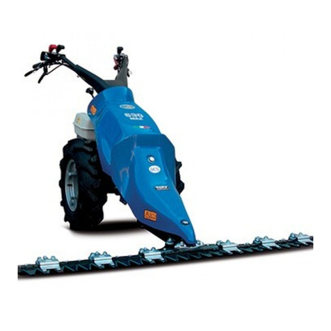
BCS ROTEX FC User manual

•FALCIACONDIZIONATRICE
•MOWER CONDITIONER ROTEX R5
•FAUCHEUSES – CONDITIONNEUSE MOD. ROTEX R6
•SEGADORA – ACONDICIONADORA ROTEX R7
•MÄHER MIT QUETSCHVORRICHTUNG
MANUALE D’ USO E MANUTENZIONE Codice 90103067 Edizione
OWNER’ S MANUAL Code 90103067 Edition
MANUEL D’ ENTRETIEN Code 90103067 Edition 12/10
MANUAL DE USO Y MANTENIMIENTO Codigo 90103067 Edición
WARTUNGSANLEITUNG Kodezahl 90103067 Ausgabe
BCS SpA - V.le Mazzini, 161 - 20081 ABBIATEGRASSO - MI - Italia

2
I
Le macchine comprese in questo manuale
sono costruite in accordo con la Direttiva
Macchine Europea e sue modificazioni.
La società BCS si complimenta con Voi per la scelta di un
nostro prodotto garantendoVi il massimo dell’assistenza e
della collaborazione che da sempre contraddistinguono il
nostro marchio.
Questa pubblicazione Vi aiuterà a conoscere meglio la
Vostra macchina. Se verrà usata seguendo queste istru-
zioni Vi durerà molti anni e Vi sarà di prezioso aiuto per
svolgere i Vostri lavori agricoli.
Vi raccomandiamo pertanto di leggere attentamente que-
ste pagine e di seguire sempre i consigli.
GB
The machines described in this manual are
built in accordance with the European
Machines Directive and its modifications.
BCS congratulates with You for Your purchasing a machi-
ne from our range. We will grant the assistance and coope-
ration which have always been a feature of our products.
If used in accordance with the instruction contained in your
owner’s manual, your machine will last many years and will
prove to be of an invaluable assistance to you.
We therefore recommend that you read the manual care-
fully and follow the advice given.
F
Les machines décrites dans ce manuel sont
construites en accord avec la Directive
Européenne des Machines et ses modifications.
La société BCS Vous félicite pour le choix d’un de nos
produits en vous assurant le maximum de notre assistance
et collaboration qui ont toujours distingué notre marque.
Cette publication vous aidera à mieux connaître votre ma-
chine. Si vous utilisez conformément aux instructions con-
tenues dans ce manuel, elle durera de nombreuses an-
nées et sera pour vous une aide précieuse pour vos tra-
vaux agricoles.
Nous vous recommandons, par conséquent, de lire ces pa-
ges avec attention et de suivre scrupuleusement les con-
seils.
E
Las máquinas incluidas en este manual
están costruidas según la Directriz Europea
de las Máquinas y sus enmiendas.
La sociedad BCS se alegra con Usted por haber escogido
nuestro producto. BCS puede asegurar la maxima asisten-
cia y collaboraciòn que siempre han caracterizado nuestra
marca.
Este libro le ayudarà a conocer mejor su màquina. Si la
usa siguiendo estas instrucciones le durerà muchõs anos y
la serà de gran ayuda para dsarrollar sus trabajos agrì-
colas.
Le recomenamos pues, leer atentamente estas pàginas y
seguir siempre los consejos que en ellas encontrarà.
D
Die in dem vorliegenden Handbuch
beschriebenen Maschinen sind der
Europäische Richtlinie über Maschinen und
ihren Abänderungen gemäß gebaut worden.
BCS erfreut sich um Ihre Wahl. Unsere Firma wird zweifel-
los Ihnen seine beste Wartung und Zusammenarbeit bie-
ten, die seit immer BCS Produkte kennzeichnen.
Wenn Sie in diesem Handbuch erteilten Anleitungen be-
herzigen, wird Ihre Maschine über lange Zeit eine wertvolle
Hilte sein.
Bitte lesen Sie daher die vorliegende Bedienungsanleitung
aufmerksam durch und befolgen Sie die erteilten Ratsch-
läge.

3
INDICE
I
SIMBOLOGIA
AVVERTENZE IMPORTANTI PER LA
SICUREZZA
INFORMAZIONI PER L’OPERATORE
CARATTERISTICHE TECNICHE
ADESIVI PER LA SICUREZZA
IDENTIFICAZIONE E MARCATURA
AGGANCIAMENTO AL TRATTORE
FERMO RIBALTABILE NELLA POSIZIONE
LAVORO
pag. 5
“ 5
“ 9
“ 10
“ 12
“ 13
“ 14
“ 16
FERMO RIBALTABILE NELLA POSIZIONE
RIPOSO
PROTEZIONE RULLO INFERIORE
SOLLEVAMENTO BARRA
BILANCIAMENTO BARRA
CIRCOLAZIONE STRADALE
CIRCOLAZIONE PASSAGGI STRETTI
GIRI PRESA DI FORZA (PdF) / VELOCITA’ DI
AVANZAMENTO
REGOLAZIONE ALTEZZA DI TAGLIO
TENSIONE CINGHIA
pag. 16
“ 17
“ 18
“ 18
“ 22
“ 22
“ 24
“ 25
“ 26
INDE
X
GB
SYMBOLS
IMPORTANT SAFETY WARNINGS
WORKER INFORMATIONS
TECHNICAL SPECIFICATIONS
LABELS WITH SAFETY INSTRUCTIONS
IDENTIFICATION AND NAME PLATE
COUPLING TO TRACTOR
UPSED DOG IN WORK POSITION
page 5
“ 5
“ 9
“ 10
“ 12
“ 13
“ 14
“ 16
UPSED DOG IN HOME POSITION
LOWER ROLLER SAFETY GUARD
BAR LIFTING
BAR BALANCING
ROAD CIRCULATION
CIRCULATING IN NARROW PLACES
POWER TAKEOFF (PTO) REVOLUTIONS /
DRIVE SPEED
CUTTING HEIGHT
BELT TENSION
page 16
“ 17
“ 18
“ 18
“ 22
“ 22
“ 24
“ 25
“ 26
INDE
X
F
SYMBOLES
IMPORTANTES MESURES DE SÉCURITÉ
INFORMATIONS POUR L’OPÉRATEUR
CARACTERISTIQUES TECHNIQUES
ADHÉSIFS POUR LA SÉCURITÉ
IDENTIFICATION ET MARQUAGE
ACCROCHAGE AU TRACTEUR
ARRET CULBUTANT EN POSITION DE
TRAVAIL
page 5
“ 5
“ 9
“ 10
“ 12
“ 13
“ 14
“ 16
ARRET CULBUTANT EN POSITION DE
REPOS
PROTECTION DU ROULEAU INFERIEUR
RELEVAGE DE LA BARRE
EQUILIBRAGE DE LA BARRE
CIRCULATION SUR ROUTE
CIRCULATION EN PASSAGES ETROITS
TOURS DE PRISE DE FORCE (PdF) /
VITESSE D'AVANCEMENT
REGLAGE DE LA HAUTEUR DE COUPE
TENSION DE LA COURROIE
page 16
“ 17
“ 18
“ 18
“ 22
“ 22
“ 24
“ 25
“ 26
INDICE
E
SIMBOLOGÍA
ADVERTENCIAS IMPORTANTES DE
SEGURIDAD
INFORMACIONES PARA EL OPERARIO
CARACTERISTICAS TECNICAS
ADHESIVOS PARA LA SEGURIDAD
IDENTIFICACÍON Y MARCA
ENGANCHE AL TRACTOR
TOPE MOVIL EN LA POSICION DE TRABAJO
pag. 5
“ 5
“ 9
“ 10
“ 12
“ 13
“ 14
“ 16
TOPE MOVIL EN LA POSICION DE REPOSO
PROTECCIÓN RULO INFERIOR
ELEVACÍON BARRA
BALANCEADO BARRA
CIRCULAR POR CARRETERA
CIRCULACION POR LUGARES ESTRECHOS
R.P.M. DE LA TOMA DE FUERZA (PdF) /
VELOCIDAD DE AVANCE
REGULACION DE LA ALTURA DE CORTE
TENSION CORREA
pag. 16
“ 17
“ 18
“ 18
“ 22
“ 22
“ 24
“ 25
“ 26
INHALT
D
SYMBOLE
WICHTIGE SICHERHEITSANWEISUNGEN
HINWEISE FÜR DEN BEDIENER
TECHNISCHE MERKMALE
SICHEREITSSELBSTKLEBER
IDENTIFIZIERUNG UND MARKIERUNG
ANKUPPELN AN DEN TRAKTOR
KIPPBARER ANSCHLAG IN
ARBEITSTELLUNG
Seite 5
“ 5
“ 9
“ 10
“ 12
“ 13
“ 14
“ 16
KIPPBARER ANSCHLAG IN
RUHESTELLUNG
UNTERE ROLLENABSICHERUNG
ANHEBEN DES MÄHBALKENS
AUSRICHTEN DES MÄHBALKENS
STRAßENVERKEHR
FAHREN IN ENGEN PASSAGEN
DREHZAHL ZAPFWELLE (PdF) /
VORSCHUBGESCHWINDIGKEIT
EINSTELLUNG DER SCHNITTHÖHE
RIEMENSPANNUNG
Seite 16
“ 17
“ 18
“ 18
“ 22
“ 22
“ 24
“ 25
“ 26

4
I
SGANCIO DI SICUREZZA
CILINDRO DI SOLLEVAMENTO
SOSTITUZIONE COLTELLI
REGOLAZIONE DEL CONDIZIONATORE
SMONTAGGIO DEL RULLO
MANUTENZIONE DEL RULLO
LUBRIFICAZIONE
BARRA DI TAGLIO
SUPPORTO DI COMANDO
SUPPORTO OSCILLANTE RULLI
SCHEMA DI LUBRIFICAZIONE
pag. 26
“ 28
“ 30
“ 32
“ 32
“ 34
“ 36
“ 36
“ 38
“ 38
“ 40
FLANGE DISCO CON LIMITATORE DI COPPIA
LAVAGGIO
DOTAZIONE
GARANZIA
CERTIFICATI E DICHIARAZIONI
PARTICOLARI DI CONSUMO
MODALITÁ DI VENDITA DEI RICAMBI
pag. 41
“ 42
“ 42
“ 43
“ 44
“ 45
“ 46
GB
SAFETY RELEASE DEVICE
LIFTING CYLINDER
BLADE REPLACEMENT
CONDITIONER POSITION
ROLLER DISASSEMBLY
ROLLER MAINTENANCE PROCEDURE
LUBRICATION
CUTTING BAR
COMMAND SUPPORT
OSCILLATING ROLLER SUPPORT
LUBRICACION PLAN
page 26
“ 28
“ 30
“ 32
“ 32
“ 34
“ 36
“ 36
“ 38
“ 38
“ 40
DISK FLANGE WITH COUPLE LIMITING
DEVICE
CLEANING PROCEDURE
EQUIPMENT PROVIDED
GUARANTEE
CERTIFICATES AND DECLARATIONS
PARTS SUBJECT TO WEAR
ORDERING SPARE PARTS
page 41
“ 42
“ 42
“ 43
“ 44
“ 45
“ 46
F
DISPOSITIF DE SÉCURITÉ
CYLINDRES DE RELEVAGE
SUBSTITUTION DES COTEAUX
REGLAGE DU CONDITIONNEUR
DEMONTAGE DU ROULEAU
ENTRETIEN DU ROULEAU
LUBRIFICATION
BARRE DE COUPE
SUPPORT DE COMMANDE
SUPPORT FLOTTANT DES ROULEAUX
SCHEMA DE GRAISSAGE
page 26
“ 28
“ 30
“ 32
“ 32
“ 34
“ 36
“ 36
“ 38
“ 38
“ 40
BRIDES DU DISQUE AVEC LIMITEUR DE
COUPLE
NETTOYAGE
PIECES DONNÉES EN DOTATION
GARANTIE
CERTIFICATS ET DÉCLARATIONS
PIECES SUJETTES A DETERIORATION
MODALITE DE VENTE DES PIECES DE
RECHANGE
page 41
“ 42
“ 42
“ 43
“ 44
“ 45
“ 46
E
DESENGANCHE DE SEGURIDAD
CILINDRO DE ELEVACÍON
SUBSTITUCÍON CUCHILLAS
REGULACIÓN DEL ACONDICIONADOR
DESMONTAJE DEL RODILLO
ENTRETENIMIENTO DEL RODILLO
LUBRICACIÓN
BARRA DE CORTE
SOPORTE DE MANDO
SOPORTE OSCILANTE RODILLOS
ESQUEMA DE LUBRICACIÓN
pag. 26
“ 28
“ 30
“ 32
“ 32
“ 34
“ 36
“ 36
“ 38
“ 38
“ 40
BRIDAS DISCO CON LIMITADOR DE PAR
LIMPIEZA
EQUIPO
GARANTIA
CERTIFICADOS Y DECLARACIONES
PIEZAS DE CONSUMO
SOLICITUD DE RECAMBIOS
pag. 41
“ 42
“ 42
“ 43
“ 44
“ 45
“ 46
D
SICHEREITSENTKUPPLUNG
HUBZYLINDER
AUSWECHSELN DER MESSER
EINSTELLUNG DES BEFEUCHTERS
ENTFERNEN DER WALZE
ROLLEN WARTUNG
SCHMIEREN
MÄHBALKEN
STEUERLAGER
SCHWINGENDES WALZENLAGER
SCHMIERUNGSPLAN
Seite 26
“ 28
“ 30
“ 32
“ 32
“ 34
“ 36
“ 36
“ 38
“ 38
“ 40
SCHEIBENFLANSCHE MIT
DREHMOMENTBEGRENZER
REINIGUNG
AUSSTATTUNG
GARANTIE
BESCHEINIGUNGEN UND
DEKLARATIONEN
VERSCHLEISSTEILE
VERKAUF DER ERSATZTEILE
Seite 41
“ 42
“ 42
“ 43
“ 44
“ 45
“ 46

5
SIMBOLOGI
A
A
VVERTENZE IMPORTANTI PER LA SICUREZZ
A
I
Imparate a riconoscere i simboli che troverete leggen-
do il manuale:
- ATTENZIONE, PERICOLO! -
Significa che dovete porre particolare attenzione
all'operazione che dovete effettuare.
- DIVIETO, NON FARE! -
Significa che non dovete assolutamente fare le
operazioni riportate sotto questo simbolo.
ATTENZIONE, PERICOLO!
•La BCS raccomanda di utilizzare la macchina esclusiva-
mente per lo scopo per cui è stata costruita e di attenersi
alle indicazioni ed alle spiegazioni riportate sul manuale.
•Lavorare sempre con indumenti adatti.
•L’uso, la preparazione e la manutenzione della macchina
è bene siano effettuate da personale qualificato.
SYMBOLS IMPORTANT SAFETY WARNINGS
GB
Learn the different symbols that you’re going to find
within this manual:
- ATTENTION, DANGER! -
It means that the user must pay great attention to
the operation he’s performing.
- THE FOLLOWING ARE STRICTLY FORBIDDEN!
This means the operator must not perform the ope-
rations indicated under this symbol.
ATTENTION, DANGER!
•BCS advices to use the machine exclusively for the pur-
pose it has been designed, and to follow thoroughly the
indications and the explanations given in the manual.
•Always wear appropriate safety clothes.
•The machine should only be used, prepared and servi-
ced by fully qualified people.
SYMBOLES IMPORTANTES MESURES DE SÉCURITÉ
F
Apprenez a reconnaître les symboles que vous
trouverez en lisant le manuel:
- ATTENTION, DANGER! -
Signifie que vous devez être particulièrement at-
tentif dans l’exécution de l’opération que vous êtes
sur le point d’effectuer.
- INTERDIT, NE RIEN FAIRE! -
Signifie que vous ne devez absolument pas faire
les opérations indiquées sous ce symbole.
ATTENTION, DANGER!
•BCS recommande d’utiliser la machine exclusivement
dans les fonctions pour lesquelles elle est conçue et de
respecter les indications et les instructions reportée dans
ce manuel.
•Porter toujours des vêtements appropriés pour travailler.
•L’usage, la préparation et l’entretien doivent être exécu-
tés par des personnes qualifiées.
SIMBOLOGÍ
A
A
DVERTENCIAS IMPORTANTES DE SEGURIDAD
E
Aprendèis a reconocer los sìmbolos que se encuen-
tran en este manual:
- ATENCIÓN, PELIGRO! -
Poner particular atenciòn a las operacciones que
tienen que ser efectuadas.
- PROHIBICIÓN, NO HACER! -
No efectuar absolutamente fare las operacciones
indicadas bajo este sìmbolo.
ATENCIÓN, PELIGRO!
•BCS recomand de utilizar la màquina exclusivamente
por el uso por el cual fue construida, y de atenerse a las
indicaciones y a las explicaciones del manual.
•Trabajar siempre con indumentaria adecuada.
•El uso, la preparaciòn y el mantenimiento de la màquina
debe ser efectuado por personal cualificado.
SYMBOLE WICHTIGE SICHERHEITSANWEISUNGEN
D
Lernen Sie di Symbole kennen, die Sie beim Lesen des
Handbuchs finden werden:
- ACHTUNG, GEFAHR! -
Das bedeutet, seien Sie Vorsicht im Durchführen
der genannten Operation.
- VERBOTEN, NICHT MACHEN! -
Das bedeutet, sie müssen nicht die Operationen,
die unter diesem Symbol beschrieben sind, durch-
führen.
ACHTUNG, GEFAHR!
•BCS Spa empfehlt den Kunden, die Maschine nur für
das Ziel, dafür man sie herzeugt hat, zu benutzen und die
Bemerkungen und Erklärungen, die in diesem Handbuch
beschrieben sind, zu folgen.
•Immer mit geeigneten Kleidern arbeiten.
•Die Maschine muss von ausgebildetem Personal vorbe-
reitet, bedient und instand gehalten werden.

6
I
•Prima di iniziare la falciatura, controllare lo stato di: di-
schi, coltelli, perni coltello e viti ed il loro corretto serraggio.
Sostituire i particolari usurati o danneggiati, utilizzando
solo ricambi originali BCS.
•Verificare che le protezioni ed i ripari, siano corretta-
mente montati ed efficienti; i teli rotti od usurati devono
essere sostituiti. Controllare che la protezione del cardano
sia montata e fissata per mezzo delle apposite catenelle.
•Prima di avviare il trattore, assicurarsi che la presa di
forza e cambio siano in folle.
•Appoggiare la barra falciante al terreno prima di inserire
la presa di forza.
•Quando i dischi iniziano a girare, allontanare eventuali
osservatori dalla rotativa.
•Ispezionare preventivamente l’area di lavoro ed aspor-
tare eventuali corpi estranei che possono danneggiare la
falciatrice o creare pericolo.
•Anche utilizzando tutti i dispositivi di protezione, si pos-
sono verificare proiezioni di sassi; è quindi raccomandabile
l’allontanamento di tutte le persone.
GB
•Before starting up the machine, check that the disks,
blades, blade pins, and screws are in correct condition and
screwed tightly. Replace any parts which are worn or
damaged, with original BCS spare parts.
•Check that all protection systems and shields are cor-
rectly mounted and in good condition; damaged or worn
protective sheets must be replaced. Check that the cardan
joint protection is mounted and attached with its appro-
priate chain.
•Before starting up the tractor, check that the PTO and
gear box are not engaged.
•Place the harvester/mower draw bar on the ground be-
fore inserting the PTO.
•When the disks begin to rotate, make sure that all
persons keep well clear of the blades.
•Before starting work, check the area carefully and remo-
ve all foreign matter or objects which could damage the
machine or cause danger.
•Even when all the protection systems are mounted on
the machine, there remains a certain danger risk from
flying stones; for this reason make certain that all persons
are kept well clear at a safe distance.
F
•
Avant de commencer à faucher, il faut contrôler l’état
des disques, des couteaux, des pivots du couteau et les
vis ainsi que leur serrage correct. Remplacer les pièces
usées ou abîmées en utilisant seulement des pièces de
rechange originales BCS.
•
Vérifier que les protections et les abris soient placés cor-
rectement et qu’ils soient efficaces; les bâches déchirées
ou abîmées doivent être remplacées. Contrôler que la pro-
tection du cardan soit placée et fixée par des chaînettes.
•
Avant de faire démarrer le tracteur, s’assurer que la pri-
se de force et la boîte de vitesse soient au point mort.
•Placer la barre faucheuse au terrain avant d’insérer la
prise de force.
•Quand les disques commencent à tourner, il faut éloi-
gner toutes les personnes qui se trouvent près de la rota-
tive.
•Contrôler avant la zone de travail et enlever tous les dé-
tritus qui peuvent abîmer la faucheuse ou créer un danger.
•Même si on utilise toutes les protections prévues il peut
y avoir une projection de cailloux, il est donc préférable de
faire éloigner toutes les personnes.
E
•Antes de empezar la siega, verificar el estado de: di-
scos, cuchillas, pivote cuchilla y tornillos y su correcto
apretamiento. Substituir las piezas desgastadas o averia-
das, utilizando sólo repuestos originales BCS.
•Verificar que las protecciones y las cubiertas de pro-
tección resulten correctamente montadas y funcionantes;
los toldos rotos o desgastados deben ser substituidos.
Controlar que la protección del cardán resulte montada y
fijada con las apropiadas cadenillas.
•Antes de poner en marcha el tractor, averiguar que la
toma de fuerza y el cambio estén en neutro.
•Apoyar la barra de corte al terreno antes de introducir la
toma de fuerza.
•Cuando los discos empiezan a rotear, alejar eventuales
observadores de la rotativa.
•Inspeccionar previamente la zona de trabajo y quitar
eventuales cuerpos extraños que puedan dañar la sega-
dora o crear peligro.
•Aun si se utilizan todas las protecciones, se pueden veri-
ficar proyecciones de piedras; es por lo tanto aconsejable
alejar todas las personas.
D
•
Vor Beginn des Mähens den Zustand der folgenden
Teile kontrollieren: Scheiben, Messer, Messerzapfen und
Schrauben, sowie deren Blockierung. Die abgenutzten
b.z.w. beschädigten Teile auswechseln; ausschließlich
BCS-Originalersatzteile verwenden.
•
Kontrollieren, dass die Absicherungen und Abdeckungen
richtig angebracht sind und funktionieren; die gerissenen
oder abgenutzten Schutzstoffe sind auszuwechseln. Über-
prüfen, dass die Kardanabdeckung angebracht und mit
den vorgesehenen Ketten befestigt ist.
•
Bevor Sie den Motor des Traktors anlassen, vergewis-
sern Sie Sich, dass die Zapfwelle und das Getriebe in
Leerlaufstellung sind.
•
Den Mähbalken auf die Erde legen, bevor die Zapfwelle
angeschlossen wird.
•
Wenn sich die Scheiben zu drehen beginnen, sind mö-
gliche Beobachter aus dem Rotationsbereich zu verwei-
sen.
•
Den Arbeitsbereich vorsorglich kontrollieren und mögli-
che Fremdkörper, welche die Mähmaschine beschädigen
oder eine Gefahr hervorrufen könnten, entfernen.
•
Selbst wenn alle Schutzmaßnahmen getroffen wurden,
können Steine fortgeschleudert werden; daher sollten alle
Personen aus dem Gefahrenbereich verwiesen werden.

7
I
•E’ consigliabile, prima di iniziare a lavorare, far con-
trollare dal concessionario, o dal centro assistenza autoriz-
zato, lo stato della macchina, sostituendo quei particolari
danneggiati o che potrebbero creare situazioni di pericolo.
•I coltelli devono essere sostituiti sempre in coppia, al fine
di evitare squilibri e vibrazioni.
•Viaggiando su strada pubblica, controllare il corretto ac-
coppiamento fra la falciatrice ed il trattore, rispettando
sempre tutte le prescrizioni del codice della strada.
•Non eseguire alcun intervento sulla macchina in mo-
vimento.
•Prima di applicare la macchina al trattore, verificare che
il senso di rotazione della PTO della macchina sia com-
patibile con il trattore.
•Si raccomanda di utilizzare le cuffie, nel caso l’operatore
sia esposto a rumore superiore a 85 dBA.
GB
•Before starting to use the machine, it is advisable to
have it controlled by the sales agent or by an authorised
service centre, replacing any parts which are worn or
damaged, or which could cause risk of danger.
•The blades must always be replaced pair by pair to avoid
incorrect balance or vibration.
•When driving on public roads, check the coupling bet-
ween the harvester and tractor very carefully, and always
observe all safety precautions according to the road code.
•Never carry out any repairs or adjustments while the
machine is running.
•Before attaching the machine to the tractor, check that
the machine PTO rotation direction is compatible with the
tractor.
•It is strongly recommended that earphones be worn
where noise levels exceed 85 dBA.
F
•Avant de commencer le travail nous conseillons de faire
contrôler par le concessionnaire ou par le centre d’assi-
stance autorisé, l’état de la machine et de faire remplacer
les pièces abîmées ou qui pourraient créer des situations
de danger.
•
Les couteaux doivent toujours être remplacés deux á
deux afin d’éviter des déséquilibres et des vibrations.
•
En parcourant les routes il faut contrôler que la fau-
cheuse et le tracteur soient en couple en respectant tou-
jours le code de la route.
•
N’effectuer aucune intervention sur la machine quand
elle fonctionne.
•
Avant d’appliquer la machine au tracteur il faut vérifier
que le sens de rotation de la PTO de la machine soit com-
patible avec le tracteur.
•Si l’opérateur est exposé á un bruit supérieur á 85 dBA,
il doit utiliser des écouteurs.
E
•Antes de empezar a trabajar, se aconseja de hacer veri-
ficar el estado de la máquina por el concesionario o por el
centro de asistencia autorizado, substituyendo aquellas
piezas que fuesen averiadas o que podrían crear situacio-
nes de peligro.
•Las cuchillas deben siempre ser substituidas en par,
para evitar desequilibrados y vibraciones.
•Viajando en carretera pública, verificar el correcto aco-
plamiento entre la segadora y el tractor, respetando siem-
pre todas las disposiciones del código de la circulación.
•No efectuar ninguna intervención sobre la máquina en
movimiento.
•Antes de acoplar la máquina al tractor, verificar que el
sentido de rotación de la PTO de la máquina resulte ser
compatible con el tractor.
•Se aconseja de utilizar los gorros si el operario está
sometido a ruido superior a los 85 dBA.
D
•Vor Arbeitsbeginn ist der Zustand der Maschine von
einem Wiederverkäufer bzw. von der berechtigten Service-
stelle kontrollieren zu lassen; dabei sind beschädigte Teile
oder Bauteile, die eine Gefahr hervorrufen könnten, auszu-
wechseln.
•Die Messer sind immer paarweise auszuwechseln, damit
Unwucht und Vibrationen ausgeschlossen werden können.
•Bei Fahrt auf öffentlichen Straßen ist der Anschluß zwi-
schen der Mähmaschine und dem Traktor zu kontrollieren;
es sind immer alle Vorschriften der Straßenverkehrsord-
nung zu beachten.
•Es darf kein Eingriff an der Maschine vorgenommen wer-
den, während sich diese in Bewegung befindet.
•Bevor die Maschine an den Traktor angeschlossen wird,
ist zu kontrollieren, dass der Drehsinn des PTO dem Dreh-
sinn der Maschine entspricht.
•Es sollte ein Gehörschutz getragen werden, wenn der
Bediener einer Geräuschemission ausgesetzt wird, die
oberhalb von 85 dBA liegt.

8
I
DIVIETO, NON FARE!
•Disinserendo la presa di forza, per alcuni istanti gli orga-
ni della falciatrice possono continuare, per inerzia, la rota-
zione. Non avvicinarsi alla macchina, prima dell’arresto
completo.
•Non eseguire nessun intervento di manutenzione prima
di: aver disinserito la presa di forza, spento il motore del
trattore e aver tolto la chiave di avviamento dal quadro
strumenti.
•Non azionare la macchina in prossimità o in vicinanza di
osservatori.
•Non utilizzare la macchina con i dispositivi di protezione
danneggiati.
•Non utilizzare la macchina per scopi diversi da quelli per
i quali è stata studiata.
GB
THE FOLLOWING ARE STRICLY FORBIDDEN!
•When the P.T.O is disconnected, the harvester/mower
parts will continue to rotate from inertia. Never approach
the machine until all parts have stopped moving comple-
tely.
•Never carry out any maintenance operations before ha-
ving disconnected the P.T.O, switched off the tractor mo-
tor, and removed the ignition key from the instrument pa-
nel.
•Never start up the machine with anybody nearby.
•Never use the machine if any of the protection systems
are damaged.
•Never use the machine for any work other than that for
which it was designed.
F
INTERDIT, NE RIEN FAIRE!
•
En débranchant la prise de force pour quelques instants
les organes de la faucheuse peuvent continuer la rotation
par inertie. Ne pas s’approcher de la machine avant l’arrêt
complet.
•
Ne faire aucune intervention d’entretien avant d’avoir dé-
branché la prise de force, éteint le moteur du tracteur et
avoir enlevé la clef de mise en marche du tableau de bord.
•
Ne pas faire fonctionner la machine à proximité ou près
d’observateurs.
•
Ne pas utiliser la machine s’il y a des dispositifs de pro-
tection abîmés.
•
Ne pas utiliser la machine pour d’autres buts différents
de ceux pour lesquels la machine a été projetée.
E
PROHIBICIÓN, NO HACER!
•Desconectando la toma de fuerza, durante algunos in-
stantes los órganos de la segadora pueden continuar a ro-
dear por inercia. No acercarse a la máquina antes de la
parada total.
•No efectuar ninguna intervención de entretenimiento an-
tes de: haber desconectado la toma de fuerza, apagado el
motor del tractor y haber quitado la llave de puesta en
marcha del tablero de instrumentos.
•No poner en marcha la máquina en proximidad o en
cercanía de observadores.
•No utilizar la máquina con los dispositivos de protección
averiados.
•No utilizar la máquina distintamente de la finalidad por la
cual ha sido planeada.
D
VERBOTEN, NICHT MACHEN!
•Wird die Zapfwelle ausgesteckt, können sich die Bauteile
der Mähmaschine aufgrund der Schwungkraft einige Au-
genblicke weiter drehen. Es darf sich keiner der Maschine
nähern, solange diese nicht völlig still steht.
•Es dürfen niemals Wartungsarbeiten vorgenommen wer-
den wenn: die Zapfwelle noch eingesteckt ist, der Traktor-
motor noch eingeschaltet und der Starterschlüssel noch in
der Schalttafel steckt.
•
Die Maschine nicht unmittelbar bei oder in der Nähe von
Beobachtern in Betrieb setzen.
•
Die Maschine nicht in Betrieb setzen, wenn die Schutz-
vorrichtungen beschädigt sind.
•
Die Maschine nicht für Zwecke verwenden, die von den
ursprünglich für die Maschine vorgesehenen Zwecken ab-
weichen.

9
INFORMAZIONI PER L’OPERATORE
I
ATTENZIONE
PROTEZIONE DEI LAVORATORI CONTRO I RISCHI DI ESPOSIZIONE AL RUMORE DURANTE IL LAVORO
DECRETO LEGISLATIVO 15/08/1991, n. 277
In osservanza a quanto previsto dal Decreto Legislativo n. 277 del 15/08/1991, la nostra Società informa che il gruppo
falciante comprensivo di trattore supera gli 85 dBA di rumore; pertanto, nel caso in cui il trattore non abbia una cabina
insonorizzata, l’Operatore dovrà utilizzare mezzi di protezione acustici (cuffie), come previsto dall’Art. 43.
Eventuali lavoratori, operanti nel campo d’azione della macchina, devono essere informati come previsto dall’Art. 42.
WORKER INFORMATIONS
GB
ATTENTION
WORKER PROTECTION AGAINST DANGER RISKS FROM NOISE EXPOSURE DURING WORK OPERATIONS.
DRAFT EUROPEAN STANDARD Pr En 1553
In compliance with the Draft European Standard Pr En 1553, BCS hereby declares that the disk mower/tractor combi-
nation exceeds the sound level of 85dBA. Therefore, if the tractor is not equipped with an a sound-proofed cab, the
operator must use hearing protection devices (ear muffs). Any other workers within the machine’s working range, must be
warned.
INFORMATIONS POUR L’OPERATEUR
F
ATTENTION
PROTECTION DES TRAVAILLEURS CONTRE LES RISQUES D’EXPOSITION AU BRUIT PENDANT LE TRAVAIL
DRAFT EUROPEAN STANDARD Pr En 1553
Il faut observer ce qui est prévu par le Draft European Standard Pr En 1553, et pour cela notre Société informe que le
groupe de la faucheuse ainsi que le tracteur dépasse les 85 dBA pour le bruit; donc, si le tracteur n’a pas de cabine ap-
propriée, l’Opérateur devra utiliser des moyens de protection acoustiques.
Les travailleurs qui se trouvent dans le champ d’action de la machine doivent être informés des règles prévues.
INFORMACIONES PARA EL OPERARIO
E
ATENCIÓN
PROTECCIÓN DE LOS TRABAJADORES CONTRA LOS RIESGOS DE EXPOSICIÓN AL RUIDO DURANTE EL TRABAJO
DRAFT EUROPEAN STANDARD Pr En 1553
En cumplimiento de lo previsto por el Draft European Standard Pr En 1553, nuestra empresa les informa de que nuestro
equipo de siega (incluido el tractor) supera los 85 dBA de ruido. Por lo tanto, en caso de que el tractor no tenga una
cabina insonorizada, el operador tendrá que utilizar medios de protección acústica (auriculares).
Los trabajadores que pudiera haber en el campo de acción de la máquina tienen que ser informados.
HINWEISE FÜR DEN BEDIENER
D
ACHTUNG
SCHUTZ DER ARBEITER GEGEN GEFAHREN, DURCH GERÄUSCHEMISSION WÄHREND DER ARBEIT
DRAFT EUROPEAN STANDARD Pr En 1553
Im Einklang mit der Draft European Standard Pr En 1553, teilt unsere Gesellschaft mit, daß das Mähaggregat zusammen
mit dem Traktor den Geräuschemissionswert von 85 dBA überschreitet. Sofern der Traktor nicht mit einer schalldichten
Kabine versehen ist, hat der Bediener einen geeigneten Gehörschutz zu tragen. Personen, die sich ggf. im Arbeitsbereich
der Maschine aufhalten zu informieren.

10
CARATTERISTICHE TECNICHE
Descrizione Unità di
misura Rotex R5 Rotex R6 Rotex R7
Larghezza di taglio
m 2.10 2.45 2.85
Altezza di taglio
mm 25 / 80
Larghezza dell’andana
mm 800 / 1350 1200 / 1750 1200 / 1750
Potenza richiesta alla Presa di Forza
kW (CV) 40 (54) 50 (68) 55 (75)
Velocità (senso di rotaz. Presa di Forza)
giri/min. 540 (destra)
Peso
kg 605 685 725
Senso rotaz. dischi: NORMALE
n° andane 2 3 3
Senso rotaz. dischi: CONTROROTANTE
n° andane 1 1 1
TECHNICAL SPECIFICATIONS
Description Unit of measure Rotex R5 Rotex R6 Rotex R7
Cut width
m 2.10 2.45 2.85
Cut height
mm 25 / 80
Windrow width
mm 800 / 1350 1200 / 1750 1200 / 1750
PTO power rating
kW (Hp) 40 (54) 50 (68) 55 (75)
PTO speed and rotation direction
Rpm 540 (right)
Weight
kg 605 685 725
Disk rotation direction: STANDARD
collector n° 2 3 3
Disk rotation dir.: COUNTER-ROTATION
collector n° 1 1 1
CARACTÉRISTIQUES TECHNIQUES
Désignation Unité de mesure Rotex R5 Rotex R6 Rotex R7
Largeur de coupe
m 2.10 2.45 2.85
Hauteur de coupe
mm 25 / 80
Largeur de l’andain
mm 800 / 1350 1200 / 1750 1200 / 1750
Puissance requise à la Prise de Force
kW (CH) 40 (54) 50 (68) 55 (75)
Vitesse (sens de rotation de la PdF)
tr/mn. 540 (droite)
Poids
kg 605 685 725
Sens rotation disques: STANDARD
nr. de andaines 2 3 3
Sens rot. disques: CONTRE-TOURNANT
nr. de andaines 1 1 1
CARACTERÍSTICAS TÉCNICAS
Descripción Unidad de
medida Rotex R5 Rotex R6 Rotex R7
Anchura de corte
m2.10 2.45 2.85
Altura de corte
mm 25 / 80
Anchura de la andana
mm 800 / 1350 1200 / 1750 1200 / 1750
Potencia necesaria en la PdF
kW (CV) 40 (54) 50 (68) 55 (75)
Velocidad (sentido rotación de la PdF)
r.p.m. 540 (derecha)
Peso
kg 605 685 725
Sentido rotación discos: NORMAL
n° andanas 2 3 3
Sentido rot. discos:CONTRAROTATORIO
n° andanas 1 1 1
TECHNISCHE MERKMALE
Beschreibung Maßeinheit Rotex R5 Rotex R6 Rotex R7
Schnittbreite
m 2.10 2.45 2.85
Schnitthöhe
mm 25 / 80
Reihenbreite
mm 800 / 1350 1200 / 1750 1200 / 1750
erforderliche Kraft für Zapfwelle
kW (PS) 40 (54) 50 (68) 55 (75)
Drehzahl (Drehsinn der Zapfwelle)
U/min 540 (Rechts)
Gewicht
kg 605 685 725
Drehrichtung der Scheiben: NORMAL
Anzahl der Reihen 2 3 3
Drehrichtung der Scheiben: GEGENLÄUFIG
Anzahl der Reihen 1 1 1
IGBF
E
D

11
Descrizione Rotex R5 Rotex R6 Rotex R7
Attacco al trattore
a tre punti – categoria 1 e 2
Attacco a tre punti tipo
registrabile registrabile registrabile
Equipaggiamento idraulico del trattore
1 distributore a semplice effetto con aggancio in scarico
Sollevamento
Idraulico
Inclinazione barra
35° verso il basso; 90° verso l’alto
Albero cardanico (in dotazione)
con scatto libero incorporato
Description Rotex R5 Rotex R6 Rotex R7
Tractor hitch
3-point – class 1 and 2
Three-point attachment type
adjustable adjustable adjustable
Tractor hydraulic system
1 single acting control unit with lock release mechanism
Lift
hydraulic
Bar angle
35° downwards; 90° upwards
Drive line (standard equipment)
with built in snap release
Désignation Rotex R5 Rotex R6 Rotex R7
Attelage au tracteur
3 points – cat. 1 et 2
Branchement à trois points du type
enregistrable enregistrable enregistrable
Equipement hydraulique du tracteur
1 distributeur à simple effet avec enclenchement en vidange
Relevage
hydraulique
Inclinaison de la barre
35° vers le bas; 90° vers le haut
Arbre à cardans (en équipement)
avec déclenchement libre incorporé
Descripción Rotex R5 Rotex R6 Rotex R7
Fijación al tractor
3 puntos – categoría 1 y 2
Conexión de tres puntos tipo
regulable regulable regulable
Equipamiento hidráulico del tractor
1 distribudor de efecto simple con enganche en descarga
Izado
hidráulico
Inclinación barra
35° hacia abajo; 90° hacia arriba
Árbol de cardán (en la dotación inicial)
con desenganche libre incorporado
Beschreibung Rotex R5 Rotex R6 Rotex R7
Traktoranschluß
3 Punkte – Kat. 1 und 2
Dreipunktanschluss Typ
verstellbar verstellbar verstellbar
Hydraulische Traktorausrüstung
1 einfach wirkender Verteiler mit Einhängung bei Abladung
Hub
hydraulisch
Stangenneigung
35° nach unten; 90° nach oben
Kardanwelle (gehört zur Ausstattung)
mit Freilaufkupplung
IGBF
E
D

12
ADESIVE PER LA SICUREZZA / LABELS WITH SAFETY INSTRUCTIONS / ADHÉSIFS POUR LA SÉCURITÉ /
ADHESIVOS PARA LA SEGURIDAD / SICHERHEITSSELBSTKLEBER
- GRUPPO FALCIANTE PER TRATTORI CON PdF DESTRA A 540 giri/min.
- MOWER FOR TRACTORS WITH CLOCKWISE PdF AT 540 Rpm
- GROUPE DE FAUCHAGE POUR TRACTEURS A PdF DROITE A 540 tr/mn.
- GRUPO DE SIEGA PARA TRACTORES CON PdF DERECHA A 540 R.P.M.
- MÄHAGGREGAT FÜR TRAKTOREN MIT RECHTS PdF BEI 540 U/MIN.
- INDICAZIONI PER IL CORRETTO SERRAGGIO DEI BULLONI
- STICKER DETAILING CORRECT RETAINER TIGHTENING TORQUES
- DECALCOMANIE POUR LE SERRAGE CORRECT DES ECROUS
- INDICACIONES PARA LA CORRECTA SUJECIÓN DE LOS TORNILLOS
- HINWEISE ZUM ANZIEHEN DER MUTTER-SCHRAUBEN
- PUNTO DI SOLLEVAMENTO
- RAISING POINT.
- POINT DE SOULEVEMENT
- PUNTO DE ELEVACIÓN
- HEBESTELLE
- PERICOLO: LAME TAGLIENTI
- DANGER: CUTTING BLADES
- DANGER POUR LAMES COUPANTES
- PELIGRO: CUCHILLAS CORTANTES
- GEFÄHR DURCH SCHNEIDMESSER

13
IDENTIFICAZIONE E MARCATUR
A
I
Dati di identificazione:
MARCATURA DELLA MACCHINA (fig.1)
Nella zona indicata viene stampigliato il n° di serie.
IDENTIFICAZIONE MACCHINA
Su ogni macchina viene applicata una targhetta di identifi-
cazione (fig.2).
IDENTIFICATION AND NAME PLATE
GB
Motor identification:
MACHINE NAME PLATE (fig.1)
The photo shows the location of the serial N°.
MACHINE IDENTIFICATION
An identification plate is attached to each machine (fig.2).
IDENTIFICATION ET MARQUAGE
F
Donnée d’ identification:
MARQUAGE DE LA MACHINE (fig.1)
Dans le quadre est poiçonnés le numéro de dérie.
IDENTIFICATION DE LA MACHINE
Une plaque d’identification est appliquée sur chaque ma-
chine (fig.2).
IDENTIFICACIÓN Y MARC
A
E
Datos de identificación:
MARCA DE LA MÁQUINA (fig.1)
En el recuadro viene estampillado el número de matrícula.
IDENTIFICACIÓN MÁQUINA
En cada máquina viene puesta una placa di identificación
(fig.2).
IDENTIFIZIERUNG UND MARKIERUNG
D
Motoridentifizierung:
MARKIERUNG DER MASCHINE (Bild 1)
In das Feld wird die Maschinennummer gedruckt.
IDENTIFIZIERUNG DER MASCHINE
Eine Identifizierung Typenschild wird auf jede Maschine
geklebt siehe (Bild 2).
fig.1
1 5 2 4
fig.2
7 3 8 6
1 – marchio 2 – costruttore
brand manufacturer
marque constructeur
marca constructor
Brandmal Hersteller
3 – modello 4 – motore
model motor
modele moteur
modelo motor
Modell Motor
5 – potenza del motore 6 – peso (vedi nota)
motor power weight (see note)
puissance poids (voir note)
potencia del motor peso (ver nota)
Motorsleistung Gewicht (siehe Note)
7 – numero di identificazione dell'anno di produzione
identification number of production year
numéro d'idéntif. de l'année de mise en circulation
numero de identificación de l'año de producción
Identifizierungsnummer der Produktionsjahr
8 – n° di serie
serial n°
n° de serie
n° de matricúla
Serienzahl
0000001

14
AGGANCIAMENTO AL TRATTORE
I
•Preparare il trattore e controllare che gli attacchi del sol-
levamento siano puliti.
•Assicurarsi che la macchina sia disposta in piano.
•Infilare i perni nei bracci di sollevamento (fig.1) e fissarli
con gli spilli di sicurezza A.
•Inserire l’albero cardanico e l’attacco 3°punto (fig.2 e 3).
•Infilare nel perno 3° punto anche la piastra forata B, per
fissaggio catena.
•Qualora non sia possibile montare la piastra forata per
l’aggancio catena, utilizzare il grillo in dotazione fissandolo
ad un foro della struttura del trattore.
•Collegare la tubazione del cilindro idraulico alla presa
del trattore C(fig.3) a semplice effetto con aggancio in sca-
rico.
•Agendo sulla catena, posizionare entrambi i perni di at-
tacco ai bracci del trattore a 48 / 52 cm da terra (fig.6).
NOTA: mantenere l’allineamento dei perni anche in
condizione di lavoro.
•Sollevare la macchina e alzare il piede Efissandolo con
lo spillo di sicurezza D(fig.4 e 5).
COUPLING TO TRACTOR
GB
•Make sure that links of lifting arms are greased and
clean.
•Be sure that the machine lays horizontally.
•Insert pins into lifting arms (fig.1) and secure with spin-
dles A.
•Insert cardan shaft and third point coupling shaft (fig.2
and 3).
•Fix into third point axle also chain retainer plate B.
•Otherwise use hook to link chain to any hole placed in
upper position of tractor’s rear structure.
•Insert the hydraulic connection C to the simple effect
tractor intake (fig.3) with the coupler disabled.
•Use the chain to position both fixing pins to the tractor
arms at a height of 48 / 52 cm from the ground (fig.6).
N.B. Maintain the pins in alignment even in working
conditions.
•Raise cutter bar and place the support Eleg in upper
position, locking it with safety spindle D(fig.4 and 5).
ACCROCHAGE AU TRACTEUR
F
•Préparer le tracteur et contrôler que tous les points d’at-
tache du système de relevage soient propres.
•S’assurer que la machine soit mise à niveau.
•Insérer les pivots dans les bras de relevage (fig.1) et
fixer les avec les pivots de sécurité A.
•Insérer l’arbre du cardan et l’attache au 3ème point (fig.
2 et fig.3).
•Insérer le pivot au 3ème point et la plaque Bforée pour
fixer la chaîne.
•Au cas où ce ne serait pas possible, monter la plaque
forée pour accrocher la chaîne, en la fixant, à l’aide de la
manivelle mise en dotation, à un trou de la structure du
tracteur.
•Brancher la tuyauterie du cylindre hydraulique à la prise
du tracteur C (fig.3) à simple effet avec enclenchement
dans la vidange.
•En agissant sur la chaîne, il faut placer les deux pivots
de branchement aux bras du tracteur à 48/52 cm du sol
(fig.6).
NOTE: maintenir l’alignement des pivots même dans
les conditions de travail.
•Soulever la machine et lever le pose-pied Een le fixant
avec le pivot de sécurité D (fig.4 et fig.5).
ENGANCHE AL TRACTOR
E
•Preparar el tractor y controlar que los enganches del
elevador esten limpios.
•Asegurarse de que la maquina esté plana.
•Poner los ejes en los brazos de elevaciõn (fig.1) y fijar-
los con los pasadores de seguridad A.
•Montar la transmisiõn cardánica y el ataque 3° punto
(fig.2 y fig.3).
•Poner ademãs en el eje 3° punto la pletina teladrada B,
para fijacion de la cadena.
•En caso de no ser posible el montaje de la pletina tela-
drada para el enganche de la cadena, utilizar el grillete de
dotaciõn fijãndolo a un telandro de la estructura del tractor.
•Conectar el tubo del cilindro hidráulico a la toma del
tractor C (fig.3) de efecto simple con enganche en salida.
•Moviendo la cadena, colocar ambos pernos de conexión
a los brazos del tractor, a 48/52 cm del suelo (fig.6).
NOTA: mantener la alineación de los pernos también
en condiciones de trabajo.
•Elevar a la maquina y levantar el pie Efijãndolo con el
pasador de seguridad D(fig.4 y fig.5).
ANKUPPELN AN DEN TRAKTOR
D
•Den Traktor vorbereiten und darauf achten, dass die
Anschlüsse der Hubvorrichtungen sauber sind.
•
Sicherstellen, dass die Maschine eben steht.
•
Die Zapfen in die Hebearme einführen (Bild 1) und mit
den Sicherheitsnadeln Abefestigen.
•
Die Kardanwelle und die Kupplung des 3. Punktes (Bild
2 und 3) einsetzen.
•
In den Zapfen des 3. Punktes auch die gelochte Platte
Bzur Kettenbefestigung einführen.
•
Sollte die Montage der gelochten Platte aufgrund der
Ketten Einhängung nicht möglich sein, verwenden Sie die
mitgelieferte Kurbel, die an einem Loch der Traktorstruktur
befestigt wird.
•Die Leitung des Hydraulikzylinders an die einfach wir-
kende Entladekupplung des Traktors C anschließen (Bild
3).
•Durch Drehen der Kette beide Anschlusszapfen bei 48 /
52 cm vom Boden an den Traktorarmen positionieren (Bild
6).
Achtung: Die Zapfen müssen auch im Arbeitszustand
richtig ausgerichtet sein.
•Die Maschine an und den Stützfuß Ehochheben, dann
mit der Sicherheitsnadel D(Bild 4 und Bild 5) befestigen.

15

16
FERMO RIBALTABILE NELLA POSIZIONE DI LAVORO
FERMO RIBALTABILE NELLA POSIZIONE DI RIPOSO
I
Prima di iniziare il lavoro disattivare il fermo rosso Aruo-
tandolo come indicato in fig.1.
Nota: la quota 15 mm (circa) indica che l’attacco della
barra al trattore è corretto; l’altezza da terra dei bracci
(48 - 52 cm) indicata in fig.6 a pag.15 può variare in
funzione di questa misura.
IMPORTANTE: Prima di staccare la Rotex dal trattore, al-
zare il sollevatore e attivare il fermo rosso A ruotandolo
verso il basso, lungo l’asta (fig.2).
Questa posizione mantiene l’allineamento orizzontale del
telaio e facilita il successivo aggancio del trattore.
E’ possibile variare la sporgenza laterale della macchina
adattandola alla larghezza del trattore agendo sulla mano-
vella B(fig.3).
Effettuare l’operazione con barra appoggiata a terra.
UPSED DOG IN WORK POSITION UPSED DOG IN HOME POSITION
GB
Before starting work operations, disable the red stop A by
turning it as shown in fig.1.
Note: The quota 15 mm (about) indicates that the bar
connection to the tractor is correct; the height of the
arms from the ground (48 - 52 cm) indicated in fig.6 at
page 15 can vary depending on this setting.
IMPORTANT: Before detaching the Rotex from the tractor,
raise the lifter and enable the red stop A by turning it
downwards, along the rod (fig.2).
This position allows the frame to remain in horizontal po-
sition, making easier the next connection to tractor.
It is possible to change the side position of the bar making
it suitable to tractor width operating on crank B(fig.3).
This operation should be made with bar leaning on the
ground.
ARRET CULBUTANT EN POSITION DE TRAVAIL
A
RRET CULBUTANT EN POSITION DE REPOS
F
Avant de commencer le travail, il faut débrancher l’arrêt
rouge Aen le tournant selon l’indication sur la fig.1.
Note: Le seuil de 15 mm (environ) indique que le bran-
chement de la barre au tracteur est correct; la hauteur
de terre des bras (48 - 52 cm) indiquée sur la fig.6 à la
page 15 peut changer en fonction de cette dimension.
IMPORTANT: Avant de détacher la machine Rotex du
tracteur, il faut soulever l’élévateur et activer l’arrêt rouge A
en le tournant vers le bas, le long de la tige (fig.2).
Cette position permet de maintenir l’alignement horizontal
du châssis et en facilite le prochain assemblage au trac-
teur.
Il est possible de modifier la saillie latérale de la machine
en l’adaptant à la largeur du tracteur à l’aide de la mani-
velle B(fig.3).
Effectuer cette opération avec la barre posée sur le sol.
TOPE MOVIL EN LA POSICION DE TRABAJO TOPE MOVIL EN LA POSICION DE REPOSO
E
Antes de empezar el trabajo, desactivar el retén rojo Agi-
rándolo como se indica en la fig.1.
Nota: La cota 15 mm (aprox.) indica que la conexión
de la barra al tractor es correcta. La distancia de los
brazos al suelo (48 - 52 cm) indicada en la fig.6, en la
pág.15, puede variar en función de esta medida.
IMPORTANTE: Antes de desconectar la Rotex del tractor,
levantar el elevador y activar el retén rojo A girándolo
hacia abajo, a lo largo de la varilla (fig.2).
Esta posición mantiene la alineación horizontal del chasis
y facilita el enganche posterior del tractor.
Es posible variar la parte sobresaliente del lateral de la
máquina adaptandola a la anchura del tractor accionando
en la palanca B(fig.3).
Efectuar la operación con la barra apoyada en el suelo.
KIPPBARER ANSCHLAG IN ARBEITSTELLUNG KIPPBARER ANSCHLAG IN RUHESTELLUNG
D
Vor Arbeitsbeginn ist die rote Klemmeinrichtung A zu de-
aktivieren; dazu ist diese entsprechend Bild 1 zu drehen.
Hinweis: Der Wert 15 mm (ca.) gibt an, dass der Balken
am Traktor ordnungsgemäß angeschlossen wurde; die
in Bild 6 auf Seite 15 angegebene Höhe der Arme vom
Boden (48 - 52 cm) kann je nach diesem Maß unter-
schiedlich sein.
WICHTIG: Bevor die Rotex vom Traktor entfernt wird, ist
die Hubeinrichtung hochzufahren, die rote Klemmeinrich-
tung A nach unten an der Leiste entlang drehend, einzu-
schalten (Bild 2).
Bei dieser Position bleibt die waagrechte Fluchtung des
Rahmens erhalten und es wird das spätere Ankuppeln des
Traktors ermöglicht.
Der seitliche Überstand der Maschine kann durch Betäti-
gen des Hebels B der Traktorbreite angeglichen werden
(Bild 3).
Bei diesem Verfahren muss der Mähbalken auf Boden ste-
hen.

17
PROTEZIONE RULLO INFERIORE
I
Le macchine con rulli ad incastro sono provviste della pro-
tezione rullo inferiore C(fig.4) appositamente studiata per
l’impiego su terreni sassosi; se ne consiglia lo smon-
taggio quando le caratteristiche del terreno lo consen-
tono.
LOWER ROLLER SAFETY GUARD
GB
Machines with splined rollers are fitted with a lower roller
safety guard C(fig.4), specially designed for use on stony
terrain; it is advisable to disassemble this guard when
the terrain characteristics permit it.
PROTECTION DU ROULEAU INFERIEUR
F
Les machines avec des rouleaux rainés sont munies de la
protection du rouleau inférieur C(fig.4) expressément étu-
diée pour l’utilisation sur des terrains caillouteux; on en
conseille le démontage quand les caractéristiques du
terrain le permettent.
PROTECCIÓN RULO INFERIOR
E
Las máquinas con rulos estriados están dotadas de la pro-
tección del rulo inferior C(fig.4) expresamente estudiada
para su uso en terrenos pedregosos.
Se aconseja desmontarla cuando las características
del terreno lo consientan.
UNTERE ROLLENABSICHERUNG
D
Die Maschinen mit Einrastrollen verfügen über eine untere
Rollenabsicherung C(Bild 4); diese wurde speziell für stei-
nigen Boden entwickelt; die Absicherung sollte abge-
nommen werden, wenn die Bodenmerkmale dies zu-
lassen.
A
~ 15 mm
A
C 4

18
SOLLEVAMENTO BARRA
BILANCIAMENTO BARR
A
I
ATTENZIONE, PERICOLO!
Durante il lavoro, con il limitatore di corsa Aabbassato (fig.
1) agendo sul cilindro idraulico si ottiene il sollevamento
della barra falciante per le manovre di fondo campo.
NOTA: il fermo B(fig.1) consente di alzare contempora-
neamente il supporto di comando senza dover agire anche
sui bracci di sollevamento del trattore.
Per il sollevamento totale della barra (condizione di tra-
sporto) ruotare il limitatore verso l’alto (fig.2).
Il peso a terra della barra può essere regolato agendo
sull’asta C(fig.3) e sul tirante della molla di alleggerimento.
ATTENZIONE, PERICOLO!
L’operazione deve essere eseguita a barra verticale, con
asta di sicurezza inserita e molle scariche.
Per appesantire la barra sul terreno utilizzare i fori in di-
rezione “+”, per alleggerire utilizzare i fori in direzione “-”.
Per i tagli in terreni scoscesi è consigliabile utilizzare il foro
B(fig.3).
BAR LIFTING BAR BALANCING
GB
ATTENTION, DANGER!
During work, keep the RPM limiting device Alowered
(fig.1) while acting on the hydraulic cylinder: you will obtain
the lifting of the cutting bar for the end field manoeuvres.
NOTE: the lock B (fig.1) allows to lift the command support
contemporary without acting on tractor lifting arms, too.
For the total bar lifting (transport condition), turn the limiting
device up (fig.2).
Bar weight on the ground can be set by using the Crod
(fig.3) and the tie rod of the system to lighten the spring.
ATTENTION, DANGER!
This operations must be carried out when the bar is in
vertical position with the safety rod inserted and the spring
unloaded. To make the bar weight heavier on the ground,
use the holes in the “+” direction; to lighten the bar, use the
holes in the “-” direction. When working on steep terrain, it
is advisable to use the Bhole (fig.3).
RELEVAGE DE LA BARRE EQUILIBRAGE DE LA BARRE
F
ATTENTION, DANGER!
Pendant le travail, le limiteur de course A(fig.1) en agis-
sant sur le cylindre hydraulique on obtient le relevage de la
barre fauchant pour les manoeuvres de fond.
REMARQUE: l’arrêt B(fig.1) permet de lever en même
temps le support de la commande sans agir aussi sur les
bras de relevage du tracteur.
Pour le relevage total de la barre (condition de transport)
tourner le limiteur vers le haut (fig.2)
Le poids à terre de la barre peut être réglé en agissant sur
la tige C(fig.3) et sur le tirant du ressort d’allégement.
ATTENTION, DANGER!
L’opération doit être effectué avec la barre verticale, avec
la tige de sécurité insérée et les ressorts déchargés.
Pour alourdir la barre sur le terrain, il faut utiliser les trous
en direction “+”, pour alléger il faut utiliser les trous en
direction “-”. Pour les coupes sur des terrains escarpés on
conseille d’utiliser le trou B(fig.3).
ELEVACIÓN BARR
A
BALANCEADO BARR
A
E
ATENCIÓN, PELIGRO!
Durante el trabajo, con el limitador de marcha Abajado
(fig.1), actuar sobre el cilindro hidráulico para obtener la
elevación de la barra cortante, para las maniobras de
fondo campo.
NOTA: el retén B(fig.1) permite de elevar con temporá-
neamente el soporte de mando sin ser necesario actuar
también sobre los brazos de elevación del tractor.
Para el levantamiento total de la barra (condición para el
transporte) girar el limitador hacia arriba (fig.2).
El peso al suelo de la barra puede regularse actuando
sobre la varilla C (fig.3) y sobre el tirante del muelle de ali-
geramiento.
ATENCIÓN, PELIGRO!
La operación debe efectuarse con barra vertical, con va-
rilla de seguridad conectada y muelles descargados.
Para hacer pesada la barra en el suelo utilizar los agujeros
en dirección “+”, para aligerar utilizar los agujeros en
dirección “-“. Para los cortes en terrenos accidentados se
aconseja de utilizar el agujero B(fig. 3).
ANHEBEN DES MÄHBALKENS
A
USRICHTEN DES MÄHBALKENS
D
ACHTUNG, GEFAHR!
Die Mähstange kann gehebt werden, um die Operationen
am Ende des Feldes zu erleichtern, beim Betätigung auf
dam hydraulische Zylinder, wenn der Hubbegrenzer Age-
senkt ist (Bild 1).
NOTE: Die Festellvorrichtung B(Bild 1) erlaubt zugleich
die Aufhebung der Steuerbehalter ohne auf die Hubarme
des Traktors zu betätigen.
Um die komplettes Aufhebung der Stange (beim Tran-
sport) den Hubbegrenzer abwärts drehen (Bild 2).
Das Bodengewicht des Mähbalkens kann durch Einwirken
auf den Stab C (Bild 3) und auf die Zugstange der Erleich-
terungsfeder eingestellt werden.
ACHTUNG, GEFAHR!
Der Vorgang ist bei vertikal stehendem Mähbalken, einge-
stecktem Sicherheitsstab und lastlosen Federn durchzu-
führen. Um zu gewährleisten, dass der Mähbalken stärker
auf den Boden drückt, sind die Bohrungen in "+" Richtung
zu verwenden, um die Last zu erleichtern, die Bohrungen
in "-" Richtung verwenden. Werden steile Felder gemäht,
wird empfohlen, die Bohrung B zu verwenden (Bild 3).

19
This manual suits for next models
3
Table of contents
Other BCS Lawn And Garden Equipment manuals

BCS
BCS Fresa FR 46 User manual

BCS
BCS 710 Gardener User manual

BCS
BCS RTB115441 User manual

BCS
BCS CM10 User manual

BCS
BCS 660HY WS Hydrostatic Commander User manual

BCS
BCS PowerSafe 614 PS User manual

BCS
BCS 650 User manual

BCS
BCS Action 710 User manual

BCS
BCS 921ML002 User manual

BCS
BCS 200 Series User manual