BD Diesel Performance BD-Power X-MONITOR User manual
12 May 2005 1086210 GMC/Chevy Duramax X-Monitor 1
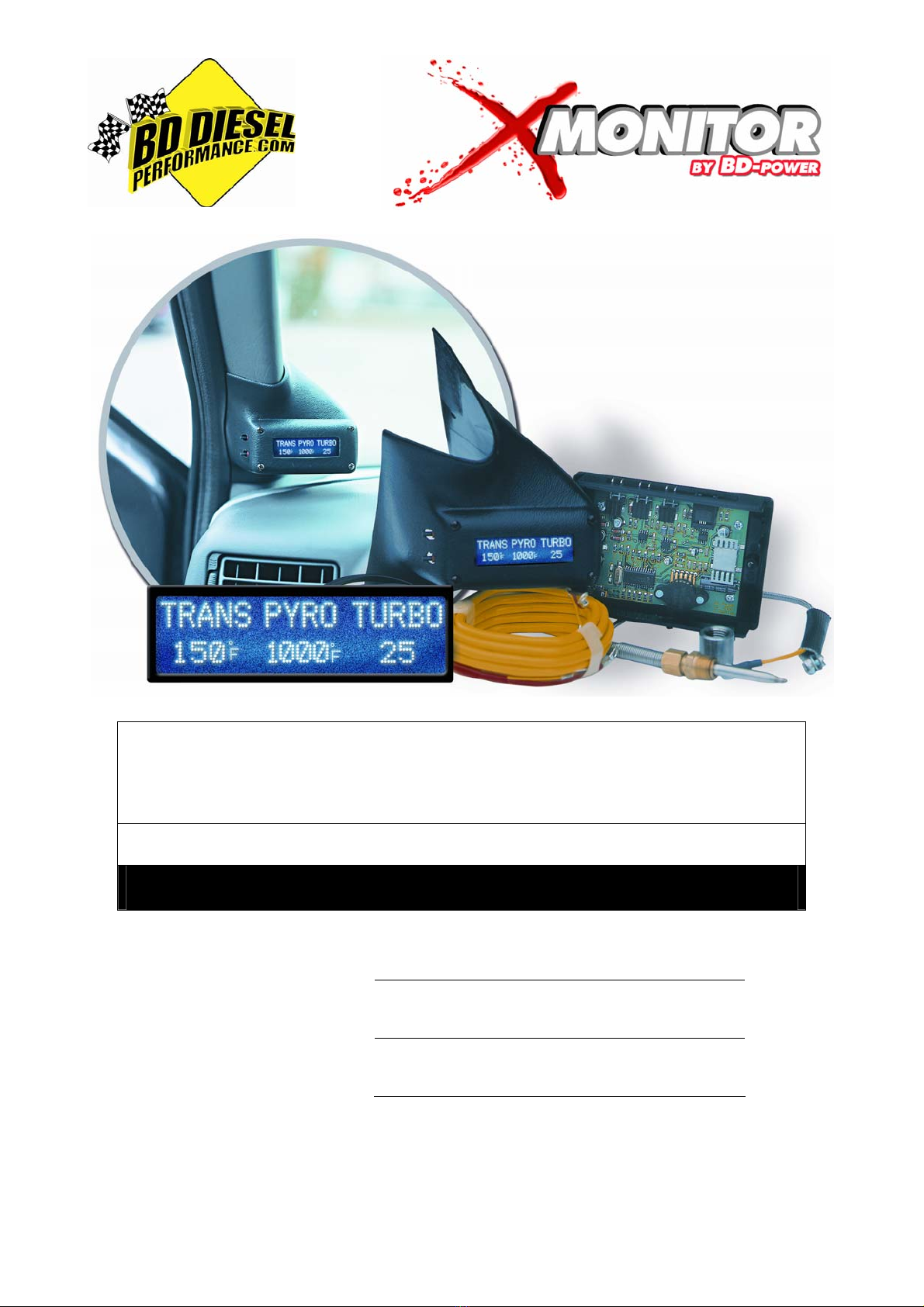
BD X-MONITOR
2001-2006 GMC/Chevy 6.6L Duramax
Installation Manual
Date Purchased
Purchased from
Installed by
READ THIS MANUAL COMPLETELY BEFORE INSTALLING THIS PRODUCT.
OWNER’S MANUAL - LEAVE IN GLOVE BOX
Installation Manual Part # I1086210
Printed in Canada
BD Engine Brake Inc.
Plant Address: Unit A10, 33733 King Rd, Abbotsford, BC, Canada V2S 7M9
U.S. Shipping Address: 88-446 Harrison St, Sumas, WA 98295 U.S. Mailing Address: P.O. Box 231, Sumas, WA 98295
Phone: 604-853-6096 Fax: 604-853-8749 Internet: www.bd-power.com

12 May 2005 1086210 GMC/Chevy Duramax X-Monitor 2
Table Of Contents
Kit Contents................................................................................................................3
Welcome ....................................................................................................................4
Pre-Installation ...........................................................................................................4
Installation..................................................................................................................5
Pyrometer Sending Unit (Thermocouple)..........................................................5
Thermocouple Wiring...............................................................................6
Boost Pressure Sender Installation...................................................................6
LB7 Motor................................................................................................6
LLY & LBZ motor .....................................................................................7
Manual Transmission / Diff Temperature Sensor..............................................8
Wiring Diagram - w/Remote Temp Sensor..............................................9
Exhaust Brake Pressure Sensor.....................................................................10
Wiring Diagram – Back Pressure...........................................................11
Engine Oil Pressure Sensor............................................................................12
2001-02 Duramax..................................................................................12
2001-02 Duramax Oil Pressure Wiring Diagram ..........................13
2003+ Duramax.....................................................................................14
2003+ Duramax Oil Pressure Wiring Diagram .............................15
Auxiliary Fuel Tank Level................................................................................16
Auxiliary Fuel Tank Level Wiring Diagram.............................................16
Power and Ground..........................................................................................17
Display Assembly Installation..........................................................................17
Programming and Set Up.........................................................................................18
Programming Chart..................................................................................................19
Operation..................................................................................................................20
X-Monitor Display Settings Flowchart ......................................................................21
Maintenance & Troubleshooting...............................................................................22
LIMITED WARRANTY STATEMENT.......................................................................23
BD Engine Brake Inc.
Plant Address: Unit A10, 33733 King Rd, Abbotsford, BC, Canada V2S 7M9
U.S. Shipping Address: 88-446 Harrison St, Sumas, WA 98295 U.S. Mailing Address: P.O. Box 231, Sumas, WA 98295
Phone: 604-853-6096 Fax: 604-853-8749 Internet: www.bd-power.com
12 May 2005 1086210 GMC/Chevy Duramax X-Monitor 3
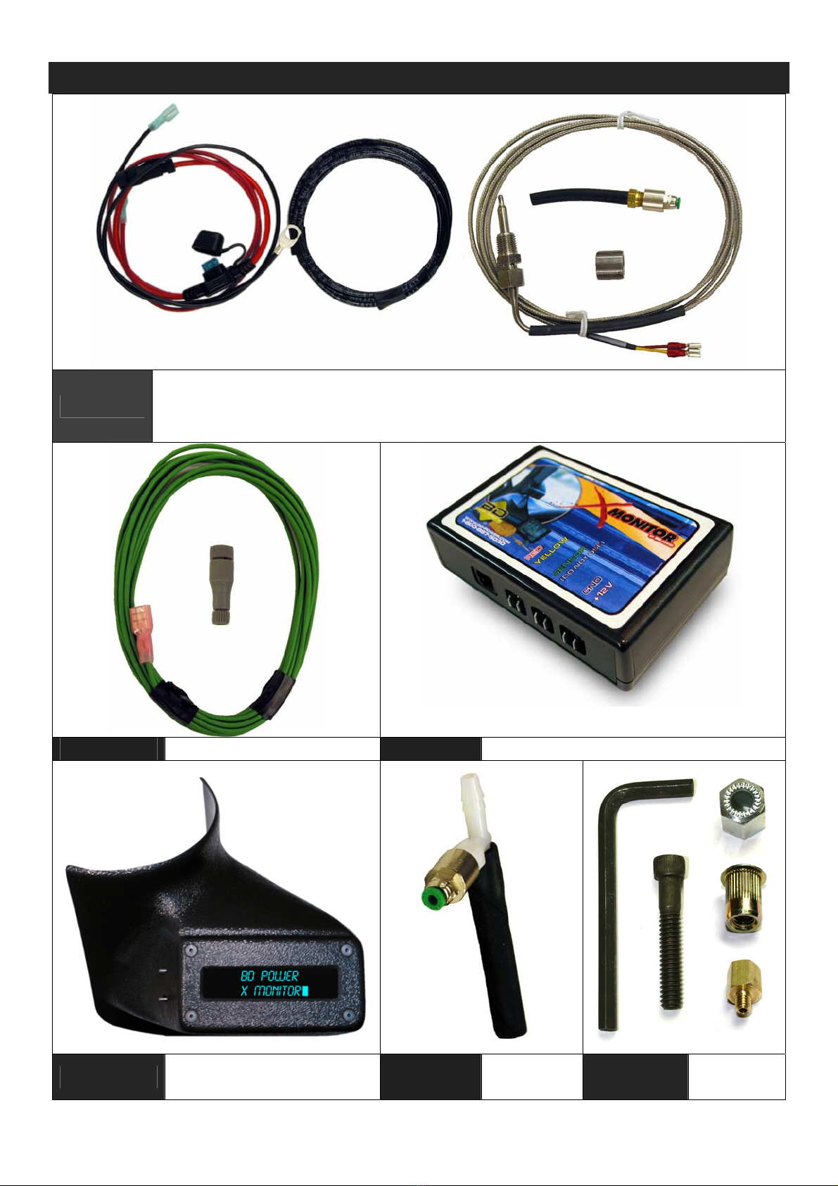
Kit Contents
1830030 Universal Installation Kit
(Includes thermocouple, bushing, control module vacuum tube boost
connection, 6ft of 1/8” air tubing, & fused power wire with ground wire)
1830010 Sensor Wire Kit 1820210 Control Module
1806200 Display Kit (Side) 1300838 LB7
Boost Kit 1300835 LLY-LBZ
Boost Kit
BD Engine Brake Inc.
Plant Address: Unit A10, 33733 King Rd, Abbotsford, BC, Canada V2S 7M9
U.S. Shipping Address: 88-446 Harrison St, Sumas, WA 98295 U.S. Mailing Address: P.O. Box 231, Sumas, WA 98295
Phone: 604-853-6096 Fax: 604-853-8749 Internet: www.bd-power.com

12 May 2005 1086210 GMC/Chevy Duramax X-Monitor 4
Welcome
Thank you for purchasing the BD X-Monitor. Your kit should have the items
mentioned on the previous page for your installation. This manual is divided into
different areas to assist you with your installation and operation of your unit.
Pre-Installation
If you have existing gauges installed, you may have to determine where to
reposition them to accommodate the X-Monitor. The X-Monitor mounts on the
driver’s side A-pillar panel, or, a custom dash-top universal kit can be purchased as
well.
This X-Monitor comes with all the programming to measure exhaust temperature
and boost pressure, plus, the option of adding one of the following: automatic
transmission temperature (using the OEM sensor), remote temperature sender (for
use with differentials for example), exhaust brake backpressure, and aftermarket
fuel tank levels.
Here are the standard list measurements:
Exhaust Gas Temperature (PYRO)
Turbo Boost Pressure (TURBO)
The above two measurements can be displayed by themselves or you can add one
of these options along with them:
Description Value BD P/N#
Transmission Temperature (TRANS) INCLUDED
Remote Oil Temp (OIL) 1080126
Exhaust Brake Back Pressure (B-PSI) 1080136
Auxiliary Tank Level (FUEL) 1080160 *
The standard kit comes with all the components and wiring to hook up the exhaust
temperature, turbo boost pressure and automatic transmission temperature (using
the trucks OEM sensor); all other applications will require one of the accessories
above to install.
* The fuel tank level accessory kit interfaces with an aftermarket level sender with a
range of 240ohms (Empty) to 33ohms (Full). Sender not included.
Once the components have been installed, the X-Monitor will have to be
programmed to match the application and the measurements being monitored. This
will be done via the buttons on the display and will be explained further in this
manual. If you wish to change from one optional measurement to another, the X
BD Engine Brake Inc.
Plant Address: Unit A10, 33733 King Rd, Abbotsford, BC, Canada V2S 7M9
U.S. Shipping Address: 88-446 Harrison St, Sumas, WA 98295 U.S. Mailing Address: P.O. Box 231, Sumas, WA 98295
Phone: 604-853-6096 Fax: 604-853-8749 Internet: www.bd-power.com
12 May 2005 1086210 GMC/Chevy Duramax X-Monitor 5
Monitor can be reprogrammed to that application but an additional accessory kit
may be required.
The following sections will give detail on the install of each measurement available
but not all will apply to your installation.
Installation
NOTE: The ground terminals of the vehicle’s batteries should be disconnected
before performing any welding or taping onto any ECM/PCM wire.
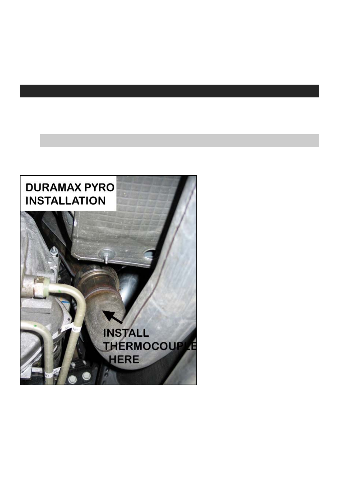
Pyrometer Sending Unit (Thermocouple)
If your existing exhaust does not have a fitting to install a pyrometer sender unit
(thermocouple), you will have to install the bushing supplied in this kit. The best
place to locate the thermocouple is in the turbo charger down pipe.
If you have a TURBO-MOUNT
EXHAUST BRAKE or an after
market down pipe installed there
may be a ¼” NPT plug already
in the system. Remove this plug
and install thermocouple into the
¼” NPT hole and tighten with an
open-end wrench.
If you have an OEM or stock
down pipe you will have to drill a
hole and then weld the bushing
that is supplied with this kit in
place. It is recommended that
you remove the existing down
pipe for ease of drilling and
welding but it is possible to
install with pipe in place. Install
thermocouple into the 1/4 pipe
tap hole and tighten with an
open-end wrench.
For advanced users, the thermocouple can be directly installed into the manifold
before the turbo. This is a more difficult installation and should only be attempted by
an experienced mechanic. When drilling and tapping the ¼” hole, be sure not to drill
into any webbing or critical areas of the exhaust manifold. When monitoring the
exhaust temperature before the turbo the critical temperature is ~1250-1300°F.
BD Engine Brake Inc.
Plant Address: Unit A10, 33733 King Rd, Abbotsford, BC, Canada V2S 7M9
U.S. Shipping Address: 88-446 Harrison St, Sumas, WA 98295 U.S. Mailing Address: P.O. Box 231, Sumas, WA 98295
Phone: 604-853-6096 Fax: 604-853-8749 Internet: www.bd-power.com

12 May 2005 1086210 GMC/Chevy Duramax X-Monitor 6
Thermocouple Wiring
Route the wire toward the firewall taking precaution to keep it away from hot and
moving parts, and then run it through the firewall by piercing a large rubber grommet
in the firewall beside the brake booster canister.
Do NOT cut or splice the thermocouple lead wire as it is special wire that
provides correct reading to the gauge. Simply coil any excess wire out of the
way.
From under the dash, retrieve the thermocouple wire and route it to the X-Monitor
Control Module. Install the wires onto the Control Module as shown in the diagram.
DO NOT MIX UP THESE WIRES, ENSURE YELLOW TO YELLOW AND RED TO
RED OR DAMAGE WILL RESULT AND WARRANTY WILL BE VOIDED.
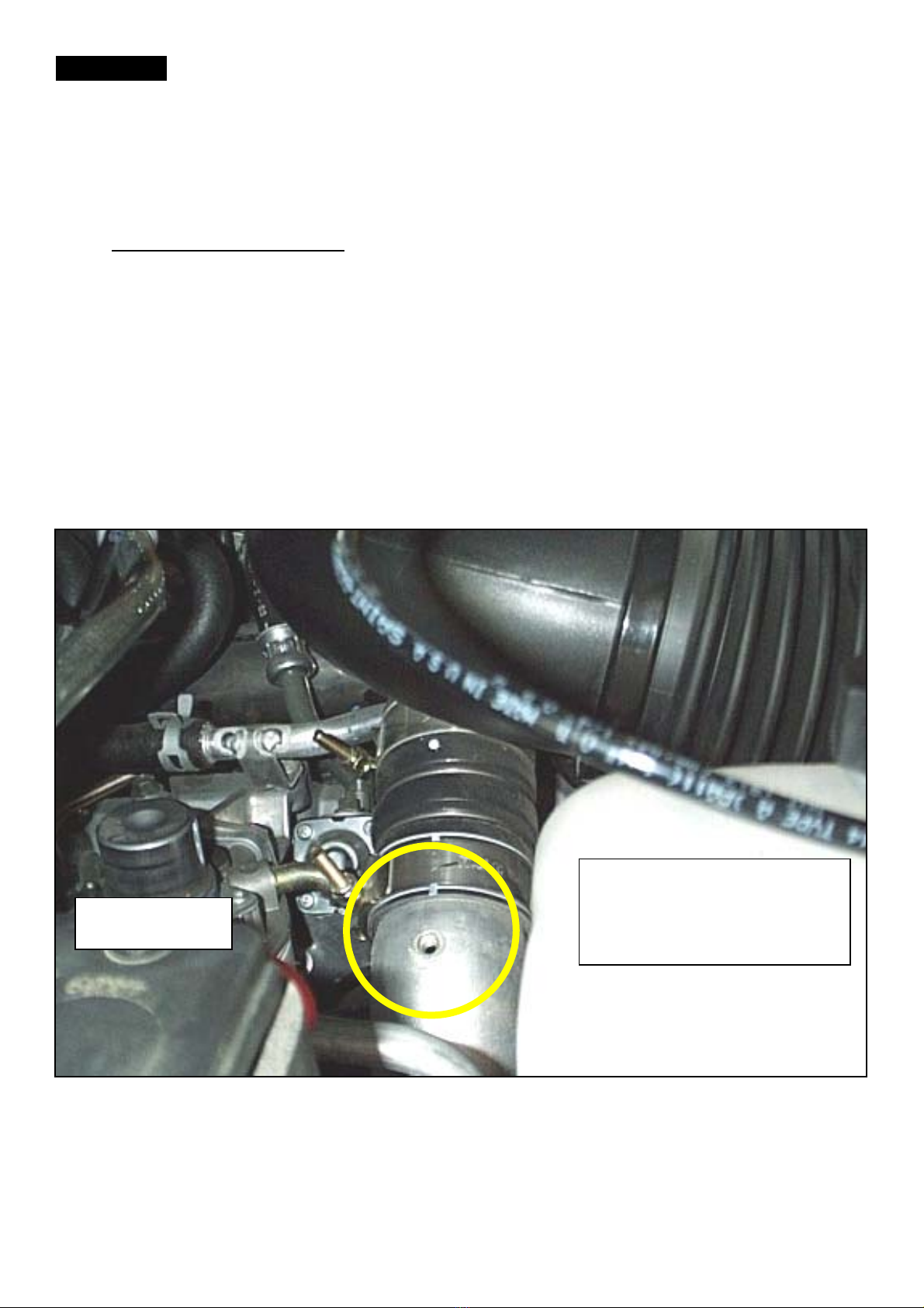
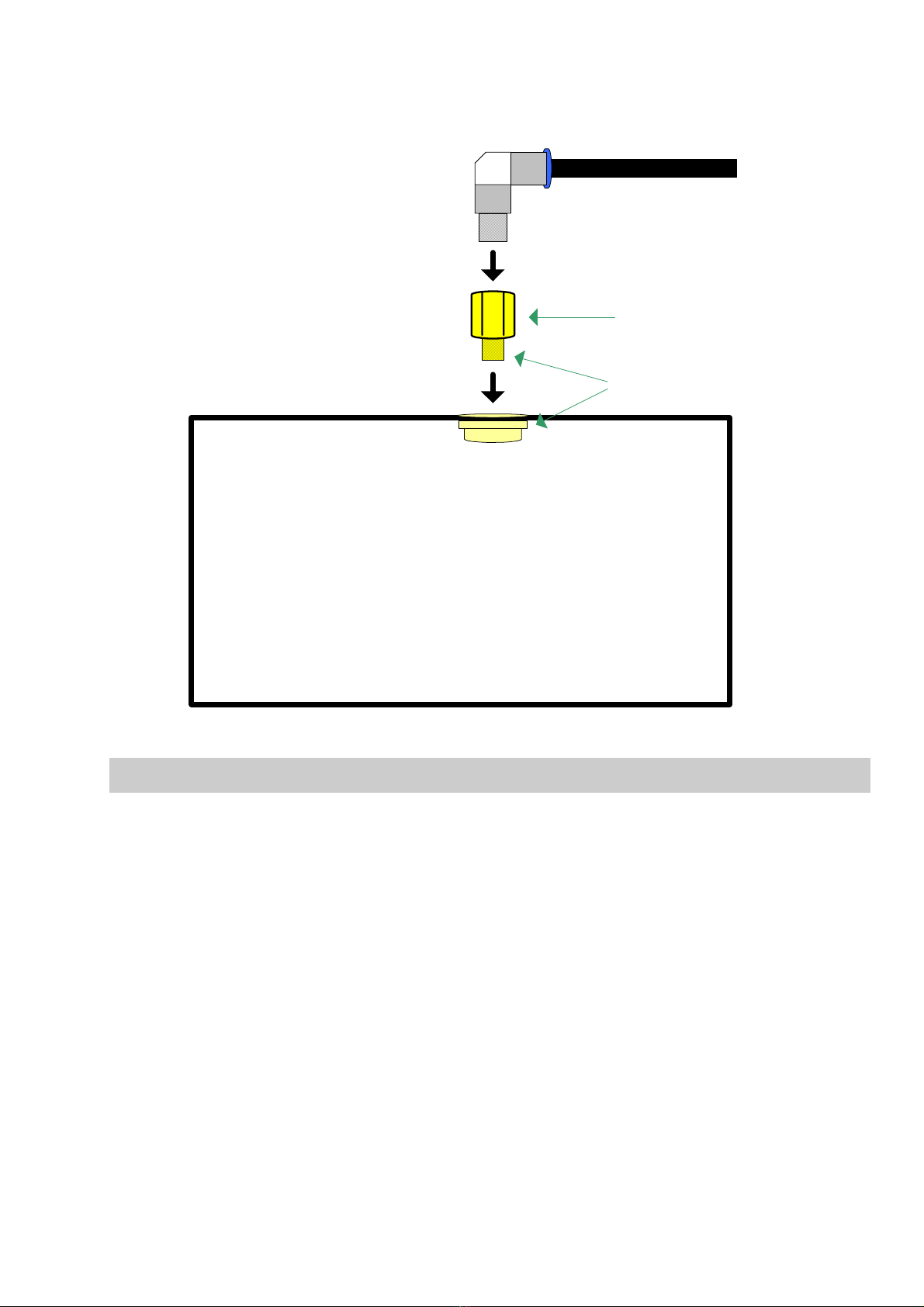
Boost Pressure Sender Installation
LB7 Motor
Locate the Turbo Wastegate hose
and follow it along to the Plenum.
Install the other end of the fitting
with the 3” hose onto the fitting of
the plenum as shown in the
photos.
Connect the supplied tubing to the
fitting and route to the inside the
cab. Push this end into the
supplied fitting (see diagram
above) and connect the short
section of rubber hose (with the
female quick-connect fitting) to the
pressure sensor on the back of
control box.
BD Engine Brake Inc.
Plant Address: Unit A10, 33733 King Rd, Abbotsford, BC, Canada V2S 7M9
U.S. Shipping Address: 88-446 Harrison St, Sumas, WA 98295 U.S. Mailing Address: P.O. Box 231, Sumas, WA 98295
Phone: 604-853-6096 Fax: 604-853-8749 Internet: www.bd-power.com
12 May 2005 1086210 GMC/Chevy Duramax X-Monitor 7
WARNING: BE SURE TO USE THE RUBBER HOSE AND NOT THE PLASTIC
TUBING WHEN MAKING THE CONNECTION TO THE CONTROL BOX.
NOTE: The module should be mounted with the boost fitting pointed down to avoid
condensation from collecting inside the module.
LLY & LBZ motor
Using a 7/16 deep socket, remove the ‘T’ clamps at either end of the intercooler
tube on the passenger side of the engine. Once this pipe is removed, drill a 3/8”
hole on the top of the pipe closest to the turbo. Use a file or de-burring wheel to
clean to hole. Coat the nutsert or rivnut with a moderate temperature silicon or
gasket maker. Insert the coated nutsert or rivnut into the 3/8” hole in the pipe. Insert
the Allen head screw through the install nut with the serrated end facing towards the
nutsert or rivnut. Use a wrench to hold the nut in place while tightening the Allen
screw with the provided Allen key. Continue to tighten the Allen key until the force
needed to turn it drastically increases. Reinstall the tube into place on the truck,
making sure the all the intercooler boots are clean of oil and the clamps are tight.
Install the 90° quick connect swivel fitting into the small brass adapter and tighten it
before installing the assembly into the nutsert. When installing the adapter assembly
into the nutsert use a small amount of silicone sealer/gasket maker around the base
of the brass adapter being careful not to obstruct the hole in the end. When
tightening the assembly into the nutsert, do not over torque or breakage will result!
Insert and tighten the
rivnut.
Fuel Filter
BD Engine Brake Inc.
Plant Address: Unit A10, 33733 King Rd, Abbotsford, BC, Canada V2S 7M9
U.S. Shipping Address: 88-446 Harrison St, Sumas, WA 98295 U.S. Mailing Address: P.O. Box 231, Sumas, WA 98295
Phone: 604-853-6096 Fax: 604-853-8749 Internet: www.bd-power.com
12 May 2005 1086210 GMC/Chevy Duramax X-Monitor 8
You can now route the nylon tubing from the quick connect nutsert assembly to the
boost input on the X-monitor. Black Nylon hose To X Monitor
Nutsert
Brass Adapter
Quick Connect
Swivel Elbow
To Intake Manifold
Use sealant here
From Intercooler
DO NOT OVER
TORQUE!
Manual Transmission / Diff Temperature Sensor
Using parts supplied in X-Monitor kit, insert the Temperature Sender into the large
bushing. This will replace the rear differential housing fill plug on the back cover. For
manual transmission temperature, locate the appropriate location for sender to fit.
NOTE: Not all locations will accommodate the size of the sender or the bushings
supplied in the kit. An alternative location may need to be found, or a sender or
bushing may have to be purchased to be installed in the desired location.
BD Engine Brake Inc.
Plant Address: Unit A10, 33733 King Rd, Abbotsford, BC, Canada V2S 7M9
U.S. Shipping Address: 88-446 Harrison St, Sumas, WA 98295 U.S. Mailing Address: P.O. Box 231, Sumas, WA 98295
Phone: 604-853-6096 Fax: 604-853-8749 Internet: www.bd-power.com
12 May 2005 1086210 GMC/Chevy Duramax X-Monitor 9
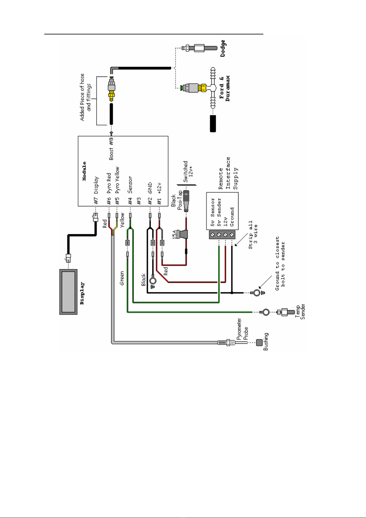
Wiring Diagram - w/Remote Temp Sensor
BD Engine Brake Inc.
Plant Address: Unit A10, 33733 King Rd, Abbotsford, BC, Canada V2S 7M9
U.S. Shipping Address: 88-446 Harrison St, Sumas, WA 98295 U.S. Mailing Address: P.O. Box 231, Sumas, WA 98295
Phone: 604-853-6096 Fax: 604-853-8749 Internet: www.bd-power.com

12 May 2005 1086210 GMC/Chevy Duramax X-Monitor 10
Exhaust Brake Pressure Sensor
Install the supplied stainless steel line and fitting into the test port of the exhaust
brake. Secure the line and attach the plastic hose.
Route the hose up along the vehicle frame and into the cab then attach the hose to
the interface filter and connect the wires as per the “Back Pressure” diagram that will
follow after this section.
Use the following diagram/photo as a guide. Install the filter and tubing together and
insert onto the inlet of the RPS Module.
The plastic filter housing will need to be changed out after 6-12 months of use. This
time is dependant on air humidity and the amount moisture trapped in the actual
filter. The replacement filter part number is 1800135. This filter should be mounted
in an easy to access, visible location.
Because of the moisture accumulating in the line and filter, it is highly recommended
that the RPS unit be mounted at the highest point of the air line causing all the
moisture to run back down the line into the exhaust.
BD Engine Brake Inc.
Plant Address: Unit A10, 33733 King Rd, Abbotsford, BC, Canada V2S 7M9
U.S. Shipping Address: 88-446 Harrison St, Sumas, WA 98295 U.S. Mailing Address: P.O. Box 231, Sumas, WA 98295
Phone: 604-853-6096 Fax: 604-853-8749 Internet: www.bd-power.com
12 May 2005 1086210 GMC/Chevy Duramax X-Monitor 11
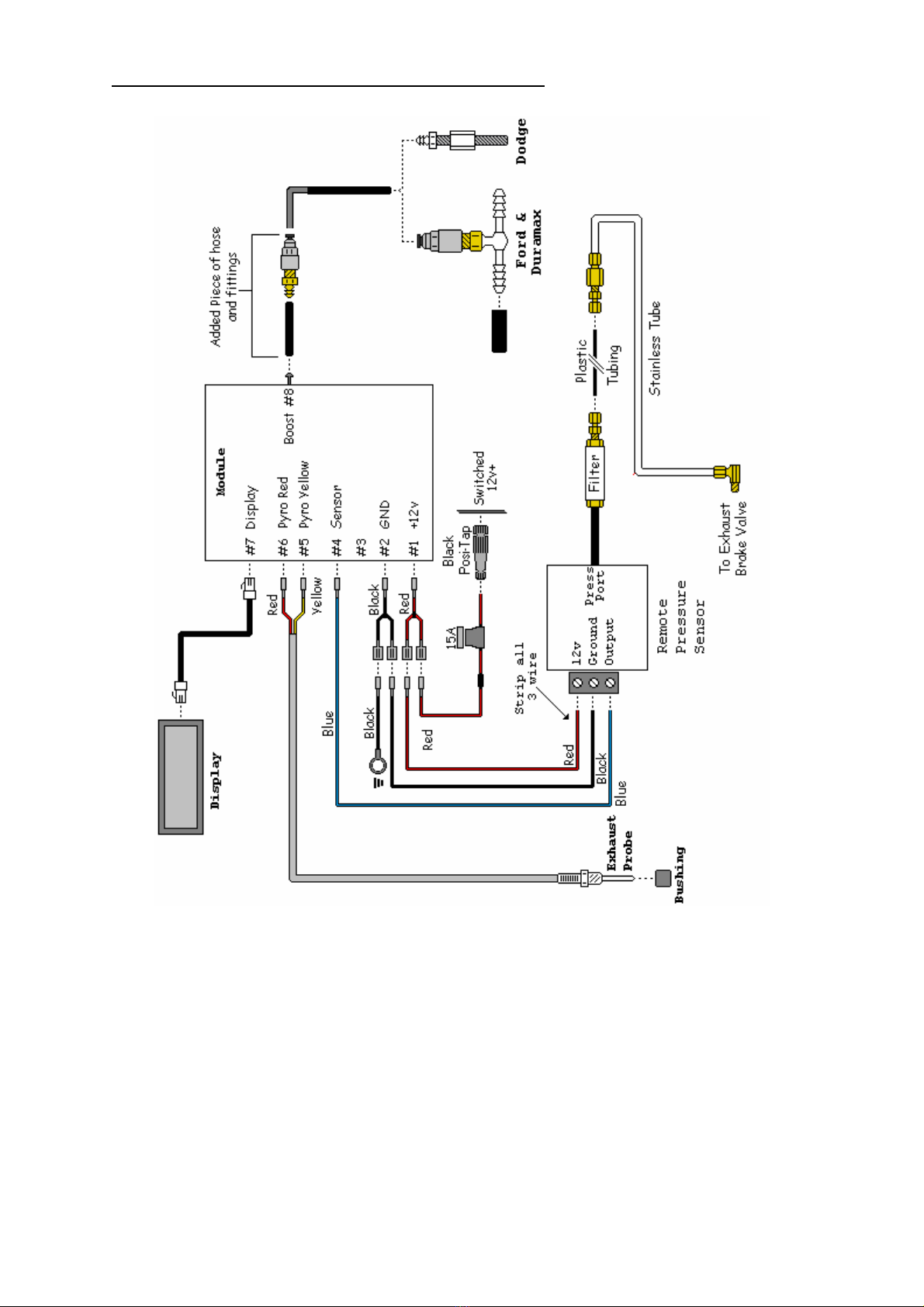
Wiring Diagram – Back Pressure
BD Engine Brake Inc.
Plant Address: Unit A10, 33733 King Rd, Abbotsford, BC, Canada V2S 7M9
U.S. Shipping Address: 88-446 Harrison St, Sumas, WA 98295 U.S. Mailing Address: P.O. Box 231, Sumas, WA 98295
Phone: 604-853-6096 Fax: 604-853-8749 Internet: www.bd-power.com
12 May 2005 1086210 GMC/Chevy Duramax X-Monitor 12
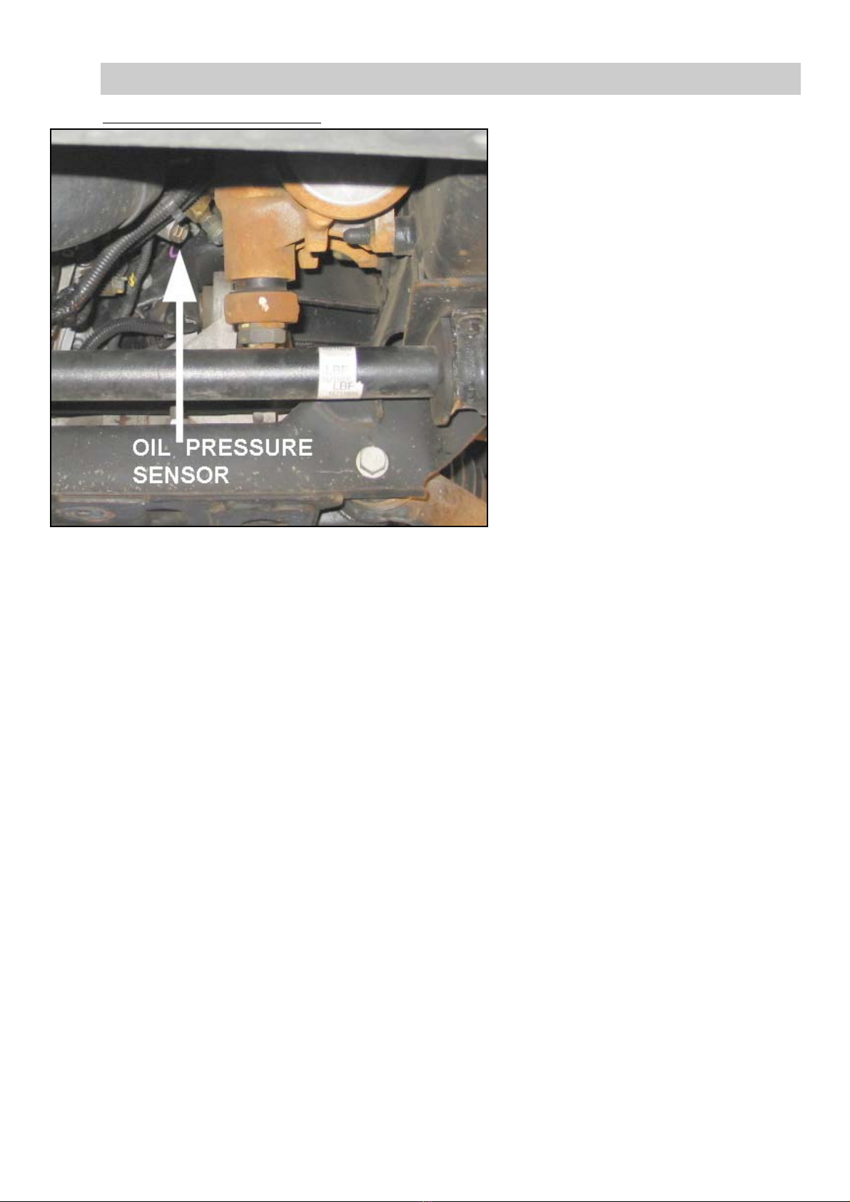
Engine Oil Pressure Sensor
2001-02 Duramax Remove the front skid plate from
the bottom of engine and locate
the oil pressure-sending unit on
left side of engine block by the
steering box.
BD Engine Brake Inc.
Plant Address: Unit A10, 33733 King Rd, Abbotsford, BC, Canada V2S 7M9
U.S. Shipping Address: 88-446 Harrison St, Sumas, WA 98295 U.S. Mailing Address: P.O. Box 231, Sumas, WA 98295
This sensor has only one (1)
wire attached.
Install a gray Posi-Tap onto the
tan w/white tracer wire of the
sensor then insert one end of the
green wire from the oil pressure
sensor kit to the gray Posi-Tap
and run the wire up into the cab.
Attach the other end of green
wire to the ‘DO NOT USE’ terminal on the control box. That’s right, this wire goes to
the ‘DO NOT USE’ terminal (this should have been labeled 'Future Expansion').
Secure the green wire in place away from any moving and/or hot parts and install
the skid plate that was removed in the first step. Tighten all fastening bolts. See
page 13 for the wiring diagram.
Phone: 604-853-6096 Fax: 604-853-8749 Internet: www.bd-power.com
12 May 2005 1086210 GMC/Chevy Duramax X-Monitor 13
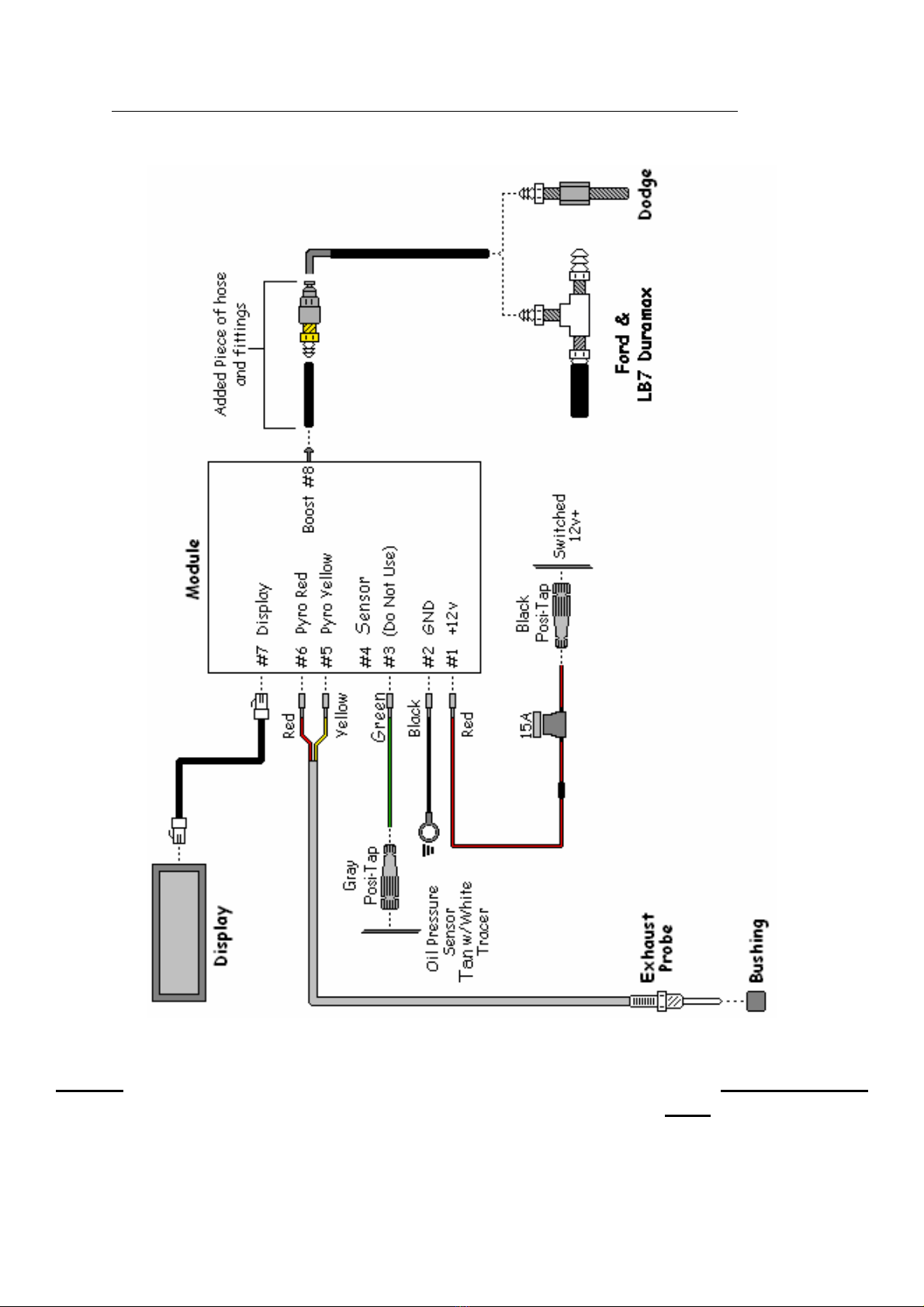
2001-02 Duramax Oil Pressure Wiring Diagram
NOTE: THE GREEN WIRE FROM THE OIL PRESSURE SENSOR IS ATTACHED
TO THE ‘DO NOT USE’ TERMINAL OF THE CONTROL BOX NOT ‘SENSOR’.
BD Engine Brake Inc.
Plant Address: Unit A10, 33733 King Rd, Abbotsford, BC, Canada V2S 7M9
U.S. Shipping Address: 88-446 Harrison St, Sumas, WA 98295 U.S. Mailing Address: P.O. Box 231, Sumas, WA 98295
Phone: 604-853-6096 Fax: 604-853-8749 Internet: www.bd-power.com
12 May 2005 1086210 GMC/Chevy Duramax X-Monitor 14
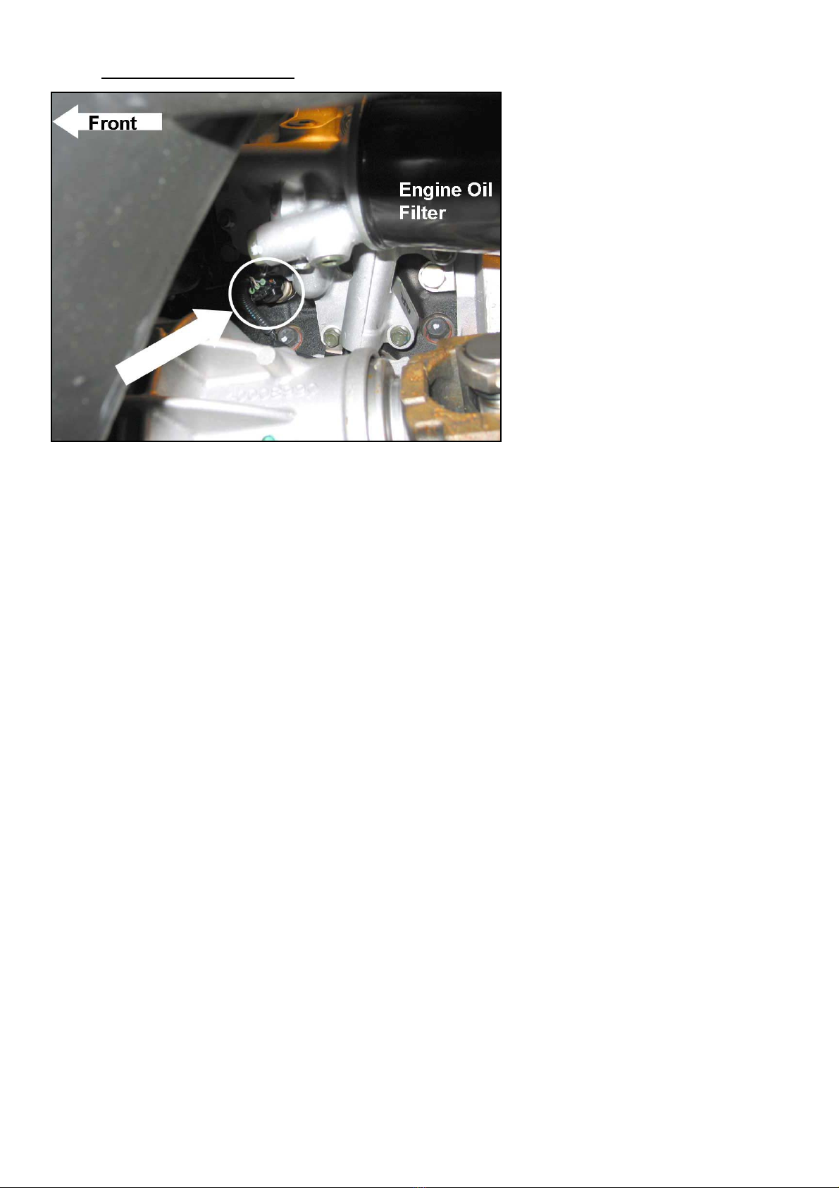
2003+ Duramax The engine oil pressure sensor
is located just in front of the
engine oil filter and housing.
This sensor has 3 wires
attached.
BD Engine Brake Inc.
Plant Address: Unit A10, 33733 King Rd, Abbotsford, BC, Canada V2S 7M9
U.S. Shipping Address: 88-446 Harrison St, Sumas, WA 98295 U.S. Mailing Address: P.O. Box 231, Sumas, WA 98295
Install a gray Posi-Tap onto the
tan w/white tracer wire of the
sensor harness then insert one
end of the green wire from the
oil pressure kit to the gray
Posi-Tap and then run the wire
up into the cab.
Attach the other end of the
green wire to the #4 ‘Sensor’
terminal on the control box.
Secure the green wire in place away from any moving and/or hot parts and install
the skid plate that was removed in the first step. Tighten all fastening bolts. See
page 15 for the wiring diagram for reference.
Phone: 604-853-6096 Fax: 604-853-8749 Internet: www.bd-power.com

12 May 2005 1086210 GMC/Chevy Duramax X-Monitor 15
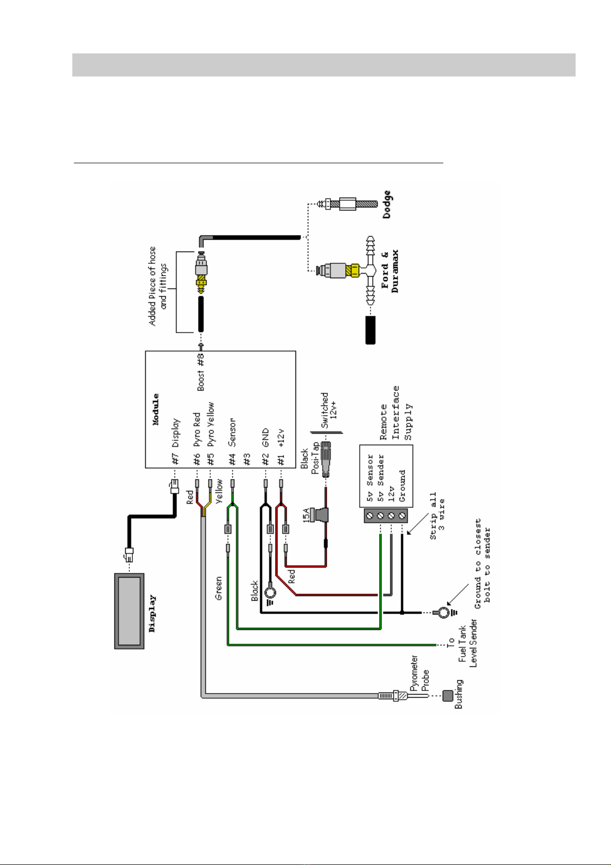
2003+ Duramax Oil Pressure Wiring Diagram
BD Engine Brake Inc.
Plant Address: Unit A10, 33733 King Rd, Abbotsford, BC, Canada V2S 7M9
U.S. Shipping Address: 88-446 Harrison St, Sumas, WA 98295 U.S. Mailing Address: P.O. Box 231, Sumas, WA 98295
Phone: 604-853-6096 Fax: 604-853-8749 Internet: www.bd-power.com
12 May 2005 1086210 GMC/Chevy Duramax X-Monitor 16
Auxiliary Fuel Tank Level
This wiring for the auxiliary fuel tank level is virtually similar to the remote
temperature installation. Consult the literature for the sender for the correct terminal
or wire for the output.
Auxiliary Fuel Tank Level Wiring Diagram
BD Engine Brake Inc.
Plant Address: Unit A10, 33733 King Rd, Abbotsford, BC, Canada V2S 7M9
U.S. Shipping Address: 88-446 Harrison St, Sumas, WA 98295 U.S. Mailing Address: P.O. Box 231, Sumas, WA 98295
Phone: 604-853-6096 Fax: 604-853-8749 Internet: www.bd-power.com

12 May 2005 1086210 GMC/Chevy Duramax X-Monitor 17
Power and Ground
Locate a switched 12-volt power source under the dash and install the Red wire to it.
Install the other end to the Power connector of the control box.
Install the Black ground loop to a good ground and install the other end to the
Ground connector of the control box.
Display Assembly Installation
* * * E X T R E M E C A U T I O N * * *
THE DISPLAY IS VERY FRAGILE AND IS INSTALLED AND
TESTED AT THE MANUFACTURER. IF YOU MUST REMOVE
THE DISPLAY IN ORDER TO PAINT THE PILLAR MOUNT
TAKE EXTREME CARE WHEN REINSTALLING. DO NOT
OVERTIGHTEN MOUNTING SCREWS OR DISPLAY WILL BE
DAMAGED AND WARRANTY WILL BE VOIDED. ***
Place the display assembly on the A-pillar to determine the best mounting location
and mark this location on the pillar. Remove the A-pillar for ease of installation.
Hold the display assembly in place on the A-pillar. Drill 3/16” holes into the corners
of the display assembly mount and also through the pillar.
Drill a hole through the A-pillar large enough for the display control wiring connector
to pass through. This hole is NOT required if you decide to run wiring along the
outside of the A-pillar.
Install the telephone-type communication cable into the back of the display circuit
board and route the wiring through the drilled hole or along the outside of the pillar
as preferred.
Insert the supplied ratchet fasteners through the drilled holes and into the A-pillar,
securing the X-Monitor display assembly to the A-pillar. Install the A-pillar into place
and route the control wiring down to the control box.
Insert the other end of the communications cable into the socket of the control box.
Once all connections are made, secure the box in place under the dash and away
from moving parts.
BD Engine Brake Inc.
Plant Address: Unit A10, 33733 King Rd, Abbotsford, BC, Canada V2S 7M9
U.S. Shipping Address: 88-446 Harrison St, Sumas, WA 98295 U.S. Mailing Address: P.O. Box 231, Sumas, WA 98295
Phone: 604-853-6096 Fax: 604-853-8749 Internet: www.bd-power.com

12 May 2005 1086210 GMC/Chevy Duramax X-Monitor 18
Programming and Set Up
Press both buttons in on the X-Monitor display
and turn on the ignition. You will get a screen
that the first line on the display will read “SIDE
OR TOP BTN?” and the bottom line reads
“SIDE”. Let go of both buttons. Press the
bottom button to go to the next screen.
BD Engine Brake Inc.
Plant Address: Unit A10, 33733 King Rd, Abbotsford, BC, Canada V2S 7M9
U.S. Shipping Address: 88-446 Harrison St, Sumas, WA 98295 U.S. Mailing Address: P.O. Box 231, Sumas, WA 98295
You will now get a screen that will read
“PART:” on the top line and “1080000” on the bottom line. Using the programming
chart located on the next page, find the program number that matches the
application and measurements you are going to program the X Monitor for. Press
the upper button until the program number appears, then press the bottom button to
activate that program. The display will now cycle through the normal start-up
screens that will appear every time the ignition is started.
It should display the following:
Phone: 604-853-6096 Fax: 604-853-8749 Internet: www.bd-power.com

12 May 2005 1086210 GMC/Chevy Duramax X-Monitor 19
Programming Chart
BD Engine Brake Inc.
Plant Address: Unit A10, 33733 King Rd, Abbotsford, BC, Canada V2S 7M9
U.S. Shipping Address: 88-446 Harrison St, Sumas, WA 98295 U.S. Mailing Address: P.O. Box 231, Sumas, WA 98295
Phone: 604-853-6096 Fax: 604-853-8749 Internet: www.bd-power.com

12 May 2005 1086210 GMC/Chevy Duramax X-Monitor 20
Operation
Once the display has gone through the startup cycle it should end up with the
following, default display.
To change the settings and set
alarm values there are 2 buttons
on the side of the display, the
bottom (MENU) button cycles
through the different modes and
the upper (MODIFY) button
controls the setting of the values.
RECOMMENDED ALARM SETTINGS:
PYRO * 900°F *
TURBO 25
TRANS 200
OIL Dependant On Location of Sender
B-PSI User Defined – Consult Exhaust Brake
Manual for safe ranges
F-PSI 3
FUEL 25
* This value based on a pyrometer probe mounted post-turbo.
These are only suggested settings and will vary depending on vehicle condition,
performance enhancements and driving techniques.
NOTES: All temperature readings are in Fahrenheit (°F), pressures are in pounds-
per-square-inch (PSI) and fuel level is displayed in percentages. All readings are
approximate and may vary due to characteristics of sensor, sender or probe, and,
certain conditions can cause interference or sway reading.
The alarm settings for fuel pressure (F-PSI), oil pressure (O-PSI) and fuel level
(FUEL) are for will display an alarm with the measurement drops below the set
value; all other measurements will alarm when the value is above the setting. The
history value also works the same where it records the lowest achieved value on F-
PSI, O-PSI and FUEL and the highest value on all others.
BD Engine Brake Inc.
Plant Address: Unit A10, 33733 King Rd, Abbotsford, BC, Canada V2S 7M9
U.S. Shipping Address: 88-446 Harrison St, Sumas, WA 98295 U.S. Mailing Address: P.O. Box 231, Sumas, WA 98295
Phone: 604-853-6096 Fax: 604-853-8749 Internet: www.bd-power.com
Table of contents
Other BD Diesel Performance Automobile Accessories manuals


Popular Automobile Accessories manuals by other brands


Weather Guard
Weather Guard ITEMIZER 314 Assembly and installation instructions

FormFit
FormFit HD 30D 10 manual

AutoWatch
AutoWatch CHOST-II owner's manual

Proseries
Proseries 1040200 quick start guide

THB Bury
THB Bury COMFORT Installation and operating manual
ICON
ICON 58990 Owner's manual & safety instructions


