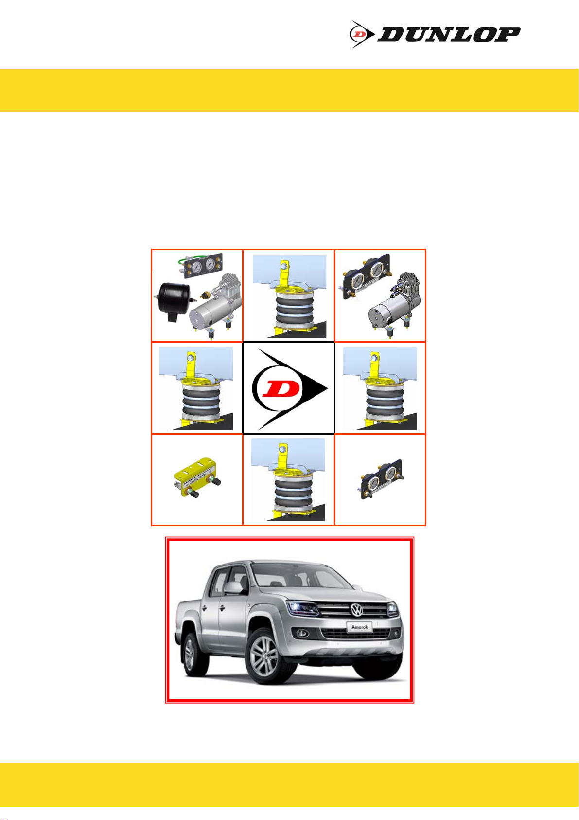
Dunlop L.AMA.10.C.L User manual

www.dunlopsystems.nl
Auxiliary Air Suspension
November 2018
Installation Manual
DUNLOP and the Flying D Device are trademarks of Dunlop International Group and are used under license by DSC Nederland B.V.
L.AMA.10.C.L
Volkswagen Amarok (2010 Onwards)

L.AMA.10.C.L
Volkswagen AMAROK
2
DUNLOP and the Flying D Device are trademarks of Dunlop International Group and are used under license by DSC Nederland B.V.
www.dunlopsystems.nl
CONTENTS
1. FOREWORD ...........................................................3
2. INTRODUCTION .....................................................4
3. VERY IMPORTANT NOTES.........................................5
4. OVERVIEW ............................................................6
5. INSTRUCTIONS FOR INSTALLATION..........................7
5.1. Preparation................................................................................7
5.2. Bump Stop Removal and fitting of Upper Bracket.............................8
5.3. Attachment of Lower Bracket and Bellow to Axle .............................8
5.4. Attachment of Upper Bracket to Bellow ..........................................9
5.5. Fitting of Inflator Console...........................................................10
5.6. Tube Connection and Disconnection, Cutting and Routing ...............12
5.7. Spring Inflation ........................................................................13
5.8. Spring Alignment......................................................................14
5.9. Maintenance.............................................................................14
5.10. Check List..............................................................................15
6. INSTALLATION PHOTOS.........................................17
7. EPILOGUE ............................................................19
© 2017, DSC Nederland B.V.
DSC Nederland B.V.
Het Wegdam 22
7496 CA Hengevelde
Nederland
Tel. :+31 (0)547 333065
Fax.:+31 (0)547 333068
e-mail: [email protected]
Website: www.dunlopsystems.nl

L.AMA.10.C.L
Volkswagen AMAROK
3
DUNLOP and the Flying D Device are trademarks of Dunlop International Group and are used under license by DSC Nederland B.V.
www.dunlopsystems.nl
1. FOREWORD
This manual provides instructions for the installation of an auxiliary air
suspension kit, developed specifically for the Volkswagen Amarok
(2010—onwards). To ensure correct installation of the kit, it is strongly
recommend that these instructions are read thoroughly before
commencing any installation work. Installation should only be carried out
by a suitably qualified mechanic or specialist installation facility. DSC
Nederland will not accept any responsibility for faults or defects arising
from incorrect installation, which automatically renders the guarantee
invalid.
IMPORTANT : Manufacturer’s Declaration Form
A manufacturer’s declaration form is provided with your kit.
Following installation of the kit please ensure that this form is
completed, signed by a qualified fitter and a copy is returned to
DSC Nederland by post, fax or e-mail. Our e-mail address is:

L.AMA.10.C.L
Volkswagen AMAROK
4
DUNLOP and the Flying D Device are trademarks of Dunlop International Group and are used under license by DSC Nederland B.V.
www.dunlopsystems.nl
2. INTRODUCTION
Thank you for choosing an auxiliary air suspension kit from the range
offered by DSC Nederland Auxiliary air suspension is fitted in tandem
with the standard steel springs of the vehicle suspension, and provides
enhancements in terms of both the stability of the vehicle and the
comfort of the passengers…
Vehicle Levelling
Simply by varying the air pressure in the springs, the vehicle can be
levelled both front-to-rear and side-to-side. Keeping the vehicle
level optimises stability, ensures correct headlamp beam distribution
and reduces tyre wear arising from uneven distribution of weight.
Straight Line Stability
Straight line stability is greatly increased at higher speeds, and when
subjected to buffeting from cross-winds or large overtaking vehicles.
Reduced Body Roll
Body roll when cornering or negotiating roundabouts is significantly
reduced.
Fatigue Reduction and Wear Compensation
Suspension fatigue is reduced, so helping to prevent leaf springs
from sagging under repeated or constant loading.
Any sagging already present can be compensated-for. This is a
particular benefit for motorhomes, which are always fully laden.
Ride Comfort
Air springs help to absorb shock loads from uneven road surfaces,
therefore general ride quality is much improved.

L.AMA.10.C.L
Volkswagen AMAROK
5
DUNLOP and the Flying D Device are trademarks of Dunlop International Group and are used under license by DSC Nederland B.V.
www.dunlopsystems.nl
3. VERY IMPORTANT NOTES
Gross Vehicle Weight (GVW)
Air assist kits are not in themselves designed to increase
the gross vehicle weight (GVW) rating of a vehicle. They
do not legally allow for carriage of a load greater than the
carrying capacity stated on the data plate of the vehicle.
Do not exceed the maximum load specified by the vehicle
manufacturer…
to avoid compromising passenger safety
to prevent possible damage to the vehicle
for legal reasons
Vehicle Uprating
Despite the above words of caution, it is possible to upgrade the weight
rating of your vehicle. This must be carried-out by a specialist supplier
that will…
carry out any necessary modifications in addition to fitting the air
assist kit
complete documentation as necessary to inform the Vehicle and
Operator Services Agency (VOSA) – a mandatory requirement
supply and fit a new weight plate to replace the original plate
supplied with the vehicle
This process applies to United Kingdom registered vehicles. The process
in other countries may be different.
This process applies to United Kingdom registered vehicles. The process
in other countries may be different.
Safety Guidance Note
The following very useful guidance note is available for free download
from the Health and Safety Executive (HSE)…
PM85, July 2007 Safe recovery (and repair) of buses and coaches fitted
with air suspension
The uniform resource locator (URL) for this document is…
http://www.hse.gov.uk/PUBNS/pm85.pdf

L.AMA.10.C.L
Volkswagen AMAROK
6
DUNLOP and the Flying D Device are trademarks of Dunlop International Group and are used under license by DSC Nederland B.V.
www.dunlopsystems.nl
4. OVERVIEW
9
11
1
8
5
3
4
10
Not in the assembly drawing...
Tie wraps`
Black hose
Inflate valves (or an option)
Declaration of conformity
Installation manual
* left side not in the assembly drawing 2 6
7
7
Number Part Number Description Quantity
1 81.11.00.1.01 TopplateRight 1
* 81.11.00.1.02 TopplateLe 1
2 81.11.00.1.01.03 Distancebushingtopplate 2
3 81.11.00.1.05 LowerbracketRight 1
* 81.11.00.1.04 LowerbracketLe 1
4 OP.LB.130‐3.CPL Airbellow130/3 2
5 DIN933‐M6x25 HexagonboltM6x25 2
6 DIN931‐M12x100 HexagonboltM12x100 2
7 DIN125A‐M12 WasherM12 4
8 OB.38240.120.001 Washer50x13x3 2
9 DIN985‐M12 SelflockingnutM12 2
10 DIN933‐M6x20 HexagonboltM6x20 8
11 DIN125A‐M6 WasherM6 8

L.AMA.10.C.L
Volkswagen AMAROK
7
DUNLOP and the Flying D Device are trademarks of Dunlop International Group and are used under license by DSC Nederland B.V.
www.dunlopsystems.nl
Preparation and Precaution
Before beginning installation, ensure that you have sufficient
clearance between the axle and the chassis. Use a jack if
necessary. Install at one side of the vehicle at a time.
Pay attention to your safety at all times during installation -
always use axle stands to support the vehicle!
The position of the axle stands should be under the chassis NOT
under the axle!
5. INSTRUCTIONS FOR INSTALLATION
The following instructions make reference to the diagrams on pages 16 to
18 inclusive.
5.1 Preparation
i. Secure the front wheels, use wheel chocks on both sides of both
front wheels.
ii. Take the ground terminal from the battery when work to electricity
is involved.
iii. Lift the rear of the vehicle till there is working space of
approximately 15 cm between bump stop and rear axle.
When both the bolt and nut are made
from steel use either class 8.8 or 10.9
For all other materials, tightening
torque is left to the discretion of a
person skilled in the art
Recommended Tightening Torque
During fitting of the air suspension system, it is recommended that nuts
and bolts are tightened in accordance with the following table...
METRICTORQUECHARTINN.m
SIZE CLASS8.8 CLASS10.9
M6x1 9.9 14.0
M8x1.25 24.0 34.0
M10x1.5 48.0 67.0
M12x1.5 61.0 89.0
M16x2 200.0 285.0

L.AMA.10.C.L
Volkswagen AMAROK
8
DUNLOP and the Flying D Device are trademarks of Dunlop International Group and are used under license by DSC Nederland B.V.
www.dunlopsystems.nl
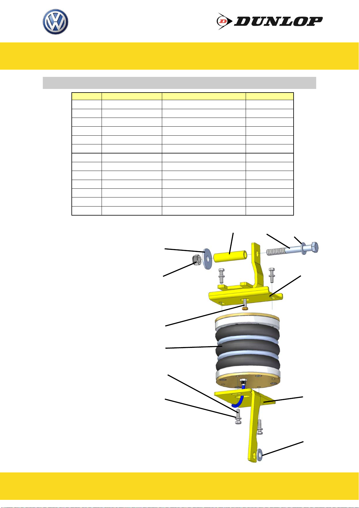
5.2 Bump Stop Removal and fitting of Upper Bracket
i. Remove the two bump stops - Figures 1, 2.
ii. Insert the Hexagon screw M6 x 25 till the tip is 1 mm on the topside
of the upper bracket - Figure 3.
iii. Shift the upper bracket in the slot of the bump stop and fully tighten
the M6 bolt in the middle, it’s to align the upper bracket in the
middle of the bump stop frame - Figure 4.
iv. Insert the M12 x 100 bolt with the big washer and the busing from
the outside towards the inside, it’s to secure the upper bracket.
Take care the busing won’t fall into the chassis beam - Figure 5.
v. Put the washer and the self locking nut M12 on the tip of the M12
bolt. Push the upper bracket upwards and tighten the screws. The
bushing is a bit shorter than the chassis, so the upper bracket will
remain tight on it’s position - Figures 6.
5.3 Attachment of Lower Bracket and Bellow to Axle
i. Insert the hose from the under side of the bracket through the
lower bracket (See Section 5.6 - “Tube Connection and
Disconnection, Cutting and Routing”) : Connect the hose to the
bellow by pushing the hose onto the air inlet port and tighten the
nut. Use black tubing for the left-hand bellow and blue for the right
-hand bellow - Figure 7.
iii. Manually compress the air bellow as flat as possible. Then bend the
end of the air hose and put a ty-wrap around it to maintain the
compressed state. Because we use ‘soft’ hose this is not a problem
to do - Figure 8.
iv. Secure the lower bracket to the air bellow by insert the hexagon
bolts M6x 20 with washer. Take care the bolts are only finger tight -
Figure 8.
v. Remove only the nut (Spanner 18 mm) of the bottom side of the
shock absorber and put a washer M12 on it - Figure 9, 10.
vi. Install the lower bracket (with air bellow) on the rear axle. The air
hose has to be at the front side of the axle. Push the lower bracket
to the rear till the metal strip of it touches the rear axle and secure
the original nut - Figure 11, 12.

L.AMA.10.C.L
Volkswagen AMAROK
9
DUNLOP and the Flying D Device are trademarks of Dunlop International Group and are used under license by DSC Nederland B.V.
www.dunlopsystems.nl
5.4 Attachment of Upper Bracket to Bellow
i. Remove the ty-wrap, so the air bellow can extend and insert the M6
x 20 hexagon bolts with washer on the top side. Bring the vehicle to
driving height, this is a height for the air bellow of approximately 15
cm - Figure 12
ii. Align the air bellow (at a height of 15 cm) and tighten the bolts at
the top and bottom side. Figure 13.

L.AMA.10.C.L
Volkswagen AMAROK
10
DUNLOP and the Flying D Device are trademarks of Dunlop International Group and are used under license by DSC Nederland B.V.
www.dunlopsystems.nl
5.5 Fitting of Inflator Console
OPTION
VALVES : Two valves and a small bracket
OPTION 1 : Two valves in a console with two independent 10-bar
pressure gauges
OPTION 2 : Two valves in a console with two independent 10-bar
pressure gauges and a rocker on/off switch to operate
the electric motor driven air compressor
OPTION 3 : Four valves (two for raising the vehicle (’UP’) and two
for lowering the vehicle (’DOWN’)) in a console with
two independent 10-bar pressure gauges. A pressure
switch operates the electric motor driven air
compressor to keep the air reservoir of 2.2-litre at
pressure.
Your kit is supplied with one of the inflator options shown above…
OPTION VALVES OPTION 1
OPTION 3OPTION 2

L.AMA.10.C.L
Volkswagen AMAROK
11
DUNLOP and the Flying D Device are trademarks of Dunlop International Group and are used under license by DSC Nederland B.V.
www.dunlopsystems.nl
Mount the console in a position of your choice whereby it is firmly fixed,
has some protection from the environment (particularly important for the
console with gauges) and is easily accessible. Suggested possible
locations include...
‘Standard’ Console…
on the rear bumper
at the rear beside the license
plate
on the chassis next to a rear
wheel
in a service shutter
(motorhomes)
beside the fuel cap
‘Option 1’, ‘Option 2’ or ‘Option 3’
Console…
in the vehicle cabin, within reach
and sight of the driver
Beside, under the driver seat
in the wall of a cupboard
(motorhomes)
in a service shutter
(motorhomes)
Comfort Package ‘Option 2’
‘Comfort’ Packages
The ‘Option 2’ and ‘Option 3’ panels, as shown above, are each part of a
Comfort Package that is supplied with a compressor (and also an air
reservoir in the case of the ‘Option 3’ panel) for ease of spring inflation
and ride height setting. For further information please ask your dealer.
The photograph below shows all of the parts of Comfort Package ‘Option
2’...

L.AMA.10.C.L
Volkswagen AMAROK
12
DUNLOP and the Flying D Device are trademarks of Dunlop International Group and are used under license by DSC Nederland B.V.
www.dunlopsystems.nl
Cutting
To achieve good sealing and air-tight fitting of tube ends to their
connecting parts, it is very important to cut tubing cleanly and squarely.
A dedicated guillotine action tubing cutter is recommended, or a craft
knife if such a tool is not available. Do not use electrician’s side cutters.
A dedicated tubing cutter -
Recommended Electrician’s Side Cutters
NOT Recommended
Connection and Disconnection
Tubes are connected as shown by the diagrams below...
5.6 Tube Connection and Disconnection, Cutting and Routing
A B C
A. Slide a nut over the end of the tube
B. Push the tube onto the connector as far as possible
C. Feed the nut up to the connector, fully tighten by hand and finally
tighten one additional turn using spanners

L.AMA.10.C.L
Volkswagen AMAROK
13
DUNLOP and the Flying D Device are trademarks of Dunlop International Group and are used under license by DSC Nederland B.V.
www.dunlopsystems.nl
Routing
Study the underside of the vehicle and decide how to route each branch
of the air circuit…
To minimise the risk of chafing, avoid running tubing over metal
edges as much as possible
Avoid close proximity to heat sources such as the exhaust assembly
Choose a route that provides as much protection as possible from
dirt, debris and any solid objects that may impact the underside of
the vehicle
It is recommended that tubes are guided alongside brake lines as much
as possible.
Use cable ties (‘tie wraps’) to secure tubing to the chassis, taking
care not to over-tighten them.
5.7 Spring Inflation
Once installation of the air assist kit is complete, inflate the springs to
achieve the desired ride height via the inflator console taking careful note
of the following...
Maximum and Minimum Pressure
Maximum Pressure 7.0bar Minimum Pressure 0.5bar
Do not exceed 7.0bar (101psi), which is the recommended
maximum charge pressure for the air springs.
The springs may be deflated if the vehicle is to be stored for a
lengthy period without use, but a pressure of at least 0.5bar
(7.25psi) should be maintained at all times in order to avoid
possible compression damage to the springs.
With the vehicle standing at the desired ride height, it is recommended
that the height of the bellow itself should be between 18cm and 22cm.

L.AMA.10.C.L
Volkswagen AMAROK
14
DUNLOP and the Flying D Device are trademarks of Dunlop International Group and are used under license by DSC Nederland B.V.
www.dunlopsystems.nl
5.9 Maintenance
Following installation, it is recommended that all metal parts are coated
with a protective substance such as body wax.
The system does not require very much maintenance other than…
to maintain air pressure in the springs. Much like a tyre, the system
may lose a little air over time.
to keep the air bellows clean. It is suggested that, when washing
the vehicle, the bellows are inspected and cleaned as necessary
(preferable by spraying). Look in particular for stones or grit
trapped between convolutes, as this may damage the bellow.
Check before and after the winter period the wax coating. Re-wax
when necessarily
5.8 Spring Alignment
i. With the vehicle standing at the desired ride height, ensure that the
springs are correctly aligned as illustrated above and then tighten
the bolts to secure the bellow to both the upper and the lower
mounting brackets.
ii. Always check if the air bellow won’t touch any obstacle
Spring out of alignment
mounting plate axes
offset
Spring in alignment
mounting plates parallel
and coaxial

L.AMA.10.C.L
Volkswagen AMAROK
15
DUNLOP and the Flying D Device are trademarks of Dunlop International Group and are used under license by DSC Nederland B.V.
www.dunlopsystems.nl
A wait of 24 hours is recommended in order to ensure that the
vehicle has maintained its stance and that there are no air leaks
present.
5.10 Check List
Before driving the vehicle following completion of installation of the
auxiliary air suspension system, please check...
...air springs set in alignment (Section 5.8)?
...enough free space around the air springs to avoid wearing?
...all metal parts wax coated (Section 5.9)?
...manufacturer’s declaration form completed and a copy returned?
...all bolts tightened to the recommended torque (Page 7)?
2

L.AMA.10.C.L
Volkswagen AMAROK
16
DUNLOP and the Flying D Device are trademarks of Dunlop International Group and are used under license by DSC Nederland B.V.
www.dunlopsystems.nl
6. INSTALLATION PHOTOS

L.AMA.10.C.L
Volkswagen AMAROK
17
DUNLOP and the Flying D Device are trademarks of Dunlop International Group and are used under license by DSC Nederland B.V.
www.dunlopsystems.nl
1 2 3
4 5 6
7 8

L.AMA.10.C.L
Volkswagen AMAROK
18
DUNLOP and the Flying D Device are trademarks of Dunlop International Group and are used under license by DSC Nederland B.V.
www.dunlopsystems.nl
CAUTION!
Before fully tightening the bolts that
secure the air spring to the upper
and lower brackets, set the vehicle
at ride height (spring height
approximately 15 cm) and ensure
that the springs are correctly
aligned.
9 10 11
12 13
Spring out of
alignment mounting
plate axes offset
Spring in alignment
mounting plates
parallel and coaxial
14
15

L.AMA.10.C.L
Volkswagen AMAROK
19
DUNLOP and the Flying D Device are trademarks of Dunlop International Group and are used under license by DSC Nederland B.V.
www.dunlopsystems.nl
6. EPILOGUE
DSC Nederland hopes that you enjoy the benefits that your DUNLOP air
suspension system will provide for you. To ensure optimal performance,
we advise that you have your system checked frequently by qualified
personnel. As recommended in the fitting instructions, it is important to
coat all the steel parts with a protective substance such as body wax.
IMPORTANT : Manufacturer’s Declaration Form
A manufacturer’s declaration form is provided with your kit.
Following installation of the kit please ensure that this form is
completed, signed by a qualified fitter and a copy is returned to
DSC Nederland by post, fax or e-mail. Our e-mail address is:
As a condition of your warranty, modifications to the system may only be
carried out by personnel of DSC Nederland.
Enquiries
For general enquiries please contact one of our dealers. You can find
them on our website.
www.dunlopsystems.nl

www.dunlopsystems.nl
DUNLOP and the Flying D Device are trademarks of Dunlop International Group and are used under license by DSC Nederland B.V.
DSC Nederland B.V.
Het Wegdam 22
7496 CA Hengevelde
Nederland
Tel. : +31 (0)547 333065
Fax. : +31 (0)547 333068
e-mail: [email protected]
Auxiliary Air Suspension
Table of contents
Other Dunlop Automobile Accessories manuals

Dunlop
Dunlop L.312.C.M User manual

Dunlop
Dunlop L.D84.C.M User manual

Dunlop
Dunlop L.CRA.17D.C.M User manual

Dunlop
Dunlop L.KI.C2-C4.C.M User manual

Dunlop
Dunlop L.412.C.M User manual

Dunlop
Dunlop L.MAS.MOV.C.M User manual

Dunlop
Dunlop L.NAV.05.C.M User manual

Dunlop
Dunlop L.IVE.65C.C.M User manual

Dunlop
Dunlop FILL&GO User manual

Dunlop
Dunlop L.SPR.18D.C.M User manual