bdiusa.com
KRONOS 6752
LIFT DESK
9
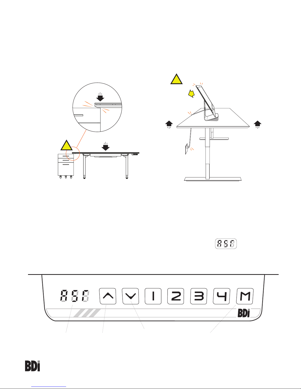
Height Adjustment
The desk base can be adjusted by pressing and holding either the UP or DOWN button until the desired height
is reached.
To program up to four presets, use the up/down buttons to find a desired height, then press “M” followed by a
number 1-4.
Caution:
Once a preset button is pushed, the desk will move to the programmed height. To stop movement, press
any button on the key pad.
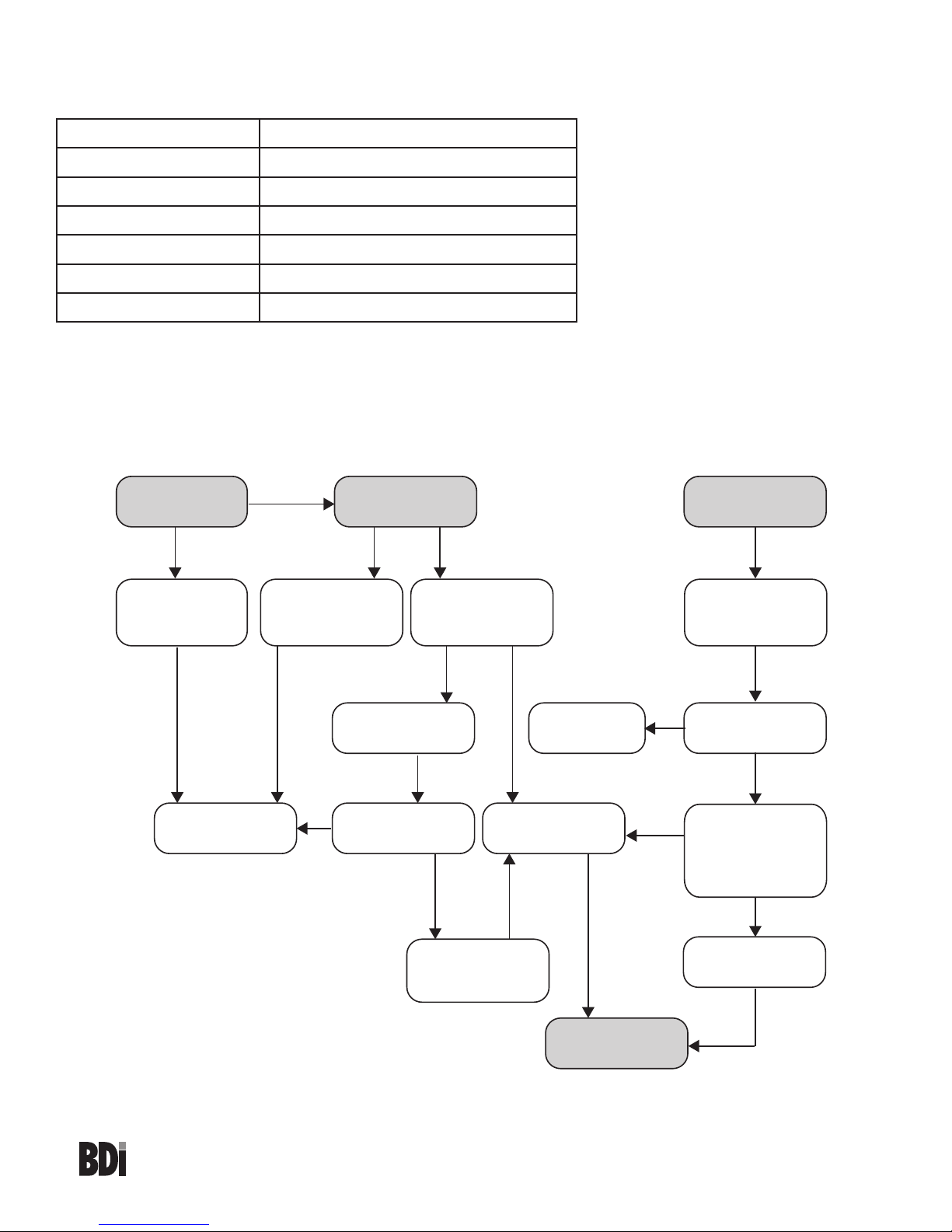
Setting the Upper and Lower Limits
The base is designed to go to its minimum and maximum heights, allowing for the widest possible range. If you
prefer to change the settings to a more narrow range, follow these steps:
Make sure the power is ON and a number reads in the LED display (if no number appears, please follow the
RESET procedure on the previous page).
Note: You must set the lower limit first, then the upper limit.
To set the Lower-limit position:
Use the UP/DOWN buttons to move the base to the desired minimum height position. Press and hold the “M”
button until the LED display flashes “S” once and let go of the button. Then press and release the “M” button
2 more times quickly. The LED display will change to “000” on the third push, and then automatically return to
show the selected height. The new lower limit is now set.
To set the Upper-limit position:
Use the UP/DOWN buttons to move the base to the desired maximum height position. Press and hold the M
button until the LED display flashes “S” once and let go of the button. Then press and release the “M” button 2
more times quickly. The LED display will change to “999” on the third push, and then automatically return to the
selected height. The new upper limit is now set.
To remove the upper/lower limit positions:
Note: You can not remove the upper/lower limits until both the upper and the lower limits have been set.
Use the UP/Down button to move the desk to any new position (other than the lower or upper limit positions).
Press and hold the “M” button until the LED display flashes “S” once and let go of the button. Then press and
release the “M” button in succession until the display changes to “555” (ignore any interim readings). After a few
seconds, the display automatically will change back to the numbered height position. The upper and lower limits
are now removed.
After the upper and lower limits are set, the previous memory positions (1,2,3,4) may be outside the new range
of movement. If so, simply reset the memory positions.
If you attempt to revise a previously set upper or lower limit and it is outside of the existing range, you will need
to remove the previously set upper/lower limits first.