NanaWall CSW75 User manual

Owner’s Manual
NanaWall CSW75
Folding Center Pivot Frameless System
This Owner’s Manual contains instructions on the installation, operation, maintenance and warranty of
the NanaWall CSW75 Folding Center Pivot Frameless System. This manual is to be used by the installer
for installation and is to be kept by the Owner for reference. Replacement parts can be ordered directly
through NanaWall Systems.
Nana Wall Systems, Inc.
100 Meadowcreek Drive #250
Corte Madera, CA 94925
800 873 5673
415 383 3148
Fax 415 383 0312
nanawall.com
©2023 Nana Wall Systems, Inc.

NANAWALL CSW75 OWNER’S MANUAL
2
Installation Instructions
The installation of the CSW75 system requires a working
knowledge and experience in the use of tools, equipment,
and methods necessary for the installation of aluminum
doors, storefronts, and/or partitions. This practice
assumes a familiarity with preparing a proper and
structurally sound opening, proper anchorage and
assumes an understanding of the fundamentals of
building construction that affect the installation of folding
center pivot frameless systems. A crew of at least 2
persons is needed. These systems can be heavy. Use safe
lifting techniques to avoid injury and product damage.
Highly recommended is using an independent NanaWall
Certified Installer, if available, or, at least, an installer
who has some experience in installing NanaWall systems.
IMPORTANT: READ COMPLETE INSTRUCTIONS
BEFORE BEGINNING INSTALLATION. INSTALL AS
RECOMMENDED; OTHERWISE, THE UNIT MAY
NOT FUNCTION PROPERLY AND ANY WARRANTY,
WRITTEN OR IMPLIED, WILL BE VOID.
CAUTION:
As regulations governing the use of glazed windows,
doors, storefronts,and/or partitions vary widely, it is the
responsibility of the building owner, architect, contractor,
or installer to insure that products selected conform to all
applicable codes and regulations, including federal, state
and local. Nana Wall Systems, Inc. can assume no
obligation or responsibility whatsoever for failure of the
building owner, architect, contractor,or installer to
comply with all applicable laws and ordinances and
safety and building codes.
Please pay special attention to the thickness of glass.
The NanaWall glass thickness for the panels is based
on the Glass Association of North America (GANA)
recommended minimum glass thickness for fully
tempered Interior butt glazed fixed glass panels.
The CSW75 system is shipped with all necessary
components. However, not included are screws, bolts,
shims, etc. to anchor the unit to the opening. The frame
is shipped knocked down and needs to be assembled.
Panels are usually pre-assembled with glass, ready to be
attached to the installed frame. In most cases, all rollers,
pivots, and lockings are pre-attached to the panels.
DESCRIPTION OF SUPPLIED PARTS
First look for an envelope in the shipment, which contains
drawings of the elevation, the layout of the unit and an
Installation Manual. This information together with the
Custom Product Drawings provided by NanaWall at the
time of order will be needed for a successful installation.
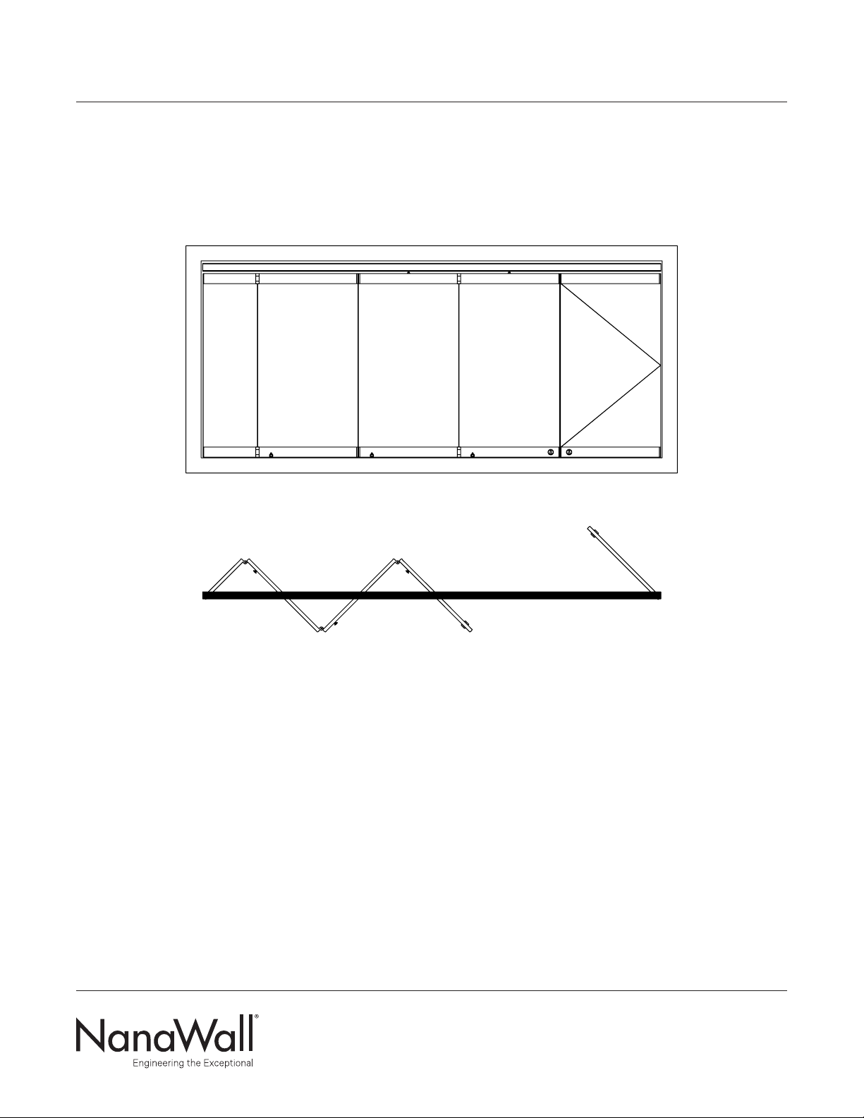
As there is no “standard” configuration for CSW75 units,
see Diagram 1 which shows the elevation and layout
of a 5 panel unit to illustrate the installation process.
Some items may not be applicable for your unit. Inspect
the custom product drawing, indicating size, configuration
and labeling of the unit ordered.
Check all parts carefully before assembly. Depending on
the unit ordered, some of these parts may already be pre-
installed on the panels. Check that the sizes of the frame
components and panels match with what was ordered.
The elevation drawing shows the sequence and number
of panels, which depends on the model ordered.
The drawing is always viewed from the outside,
but the locking shown is what is on the inside.
The panels are usually pre-assembled with one upper
carrier for each folding panel and with one specified
locking. The sequence of labeling of panels starts from
the left looking from outside with the left most panel
labeled Panel #1.

NANAWALL CSW75 OWNER’S MANUAL
3
DIAGRAM 1: EXAMPLE OF A 5 PANEL UNIT
Panel #1: folding center pivot panel
Panel #2: folding center pivot panel
Panel #3: folding center pivot panel
Panel #4: folding center pivot panel
Panel #5: single/double action end panel with pivot box or
single/double action end panel with floor closer
OUTSIDE
INSIDE
#1 #2 #3 #4 #5

NANAWALL CSW75 OWNER’S MANUAL
4
Other components include:
• Push/pull handles, other handles,or other hardware,
as ordered may not be pre-attached to the panels
and will be in the hardware box or shipped
separately.
• The layout drawing of your unit shows the upper
track components consisting of the head track in the
opening, how they are labeled and how they have to
be connected. The joints for the transitions are
indicated and necessary connectors for connecting
different upper track pieces are provided.
• The location of the removable head track (RHT)
portion to insert the rollers on panels is indicated on
the layout drawing.
• The overhead door closer will be in the hardware box
and is not pre-attached to the top rail and has to be
installed in the field after final adjustments were
made.
• Specified floor sockets, pivot points,and floor closers.
HANDLING OF COMPONENTS
1. Upon receipt, inspect the shipment to ensure it is in
good condition.
2. Make sure that all components and hardware, which
might be shipped separately do not get lost.
3. Store in a clean and dry location and protect against
defacement or damage, especially to the edges of
panels.
PREPARATION OF THE OPENING AND SUPPORT
STRUCTURE ABOVE
Make rough opening width at least 1/2"wider than the
outside unit frame width and rough opening height about
3/4"taller than the total unit height depending on how
level the support structure above is. See Sheet 2 of the
Installation Manual. It is important that the opening be
the correct size.
Product performance that includes operation, depends
on having the gap between the bottom of the panel and
the top of the finish floor be maintained at 7 mm (1/4")
and also the gap between the top of the panel and the
bottom of the head track to be maintained at a nominal
gap of 23 mm (7/8"). The running carriages can be
adjusted, if needed. The finish floor needs to be
absolutely level across the length of the opening.
The track length and layout have been supplied based on
the configuration and sizes chosen and approved. Please
refer to the layout drawing of your particular CSW75
project, to determine the correct location of the support
structure (by others) and for the support of the head
track in the plane of the opening. It is important that the
system is properly supported at the top.
IMPORTANT: Any application should take into
consideration the following:
1. As the CSW75 system is a top-hung system, it is
essential that a proper substrate with the proper
size and thickness be used for the support structure
above in order to support the head track in the
opening.
2. The structural integrity of the support structure is
critical for proper operation. Vertical deflection of
the header under full live and dead loads should be
the lesser of L/720th of the span and 1/4". It should
be designed to accommodate the total weight of the

NANAWALL CSW75 OWNER’S MANUAL
5
panels (i.e. system weight with 12 mm (1/2") tempered
glass app. 8lb/ft²) in the opening and in the stacking
area (unit in open position).
3.Structural support for lateral loads (both windload, if
any, and other lateral force) must also be provided.
4. The rough opening should be reasonably level,
plumb and square at all points. There should be no
unevenness or bowing. Make sure that the header is
not tilted or twisted. There should be no bumps on
the floor. The sides should be in the same vertical
plane and not offset of each other. A transit/laser
and other similar precise measuring equipment
should be used. YOU NEED TO ADJUST THE
FLOOR AT THE OPENING TO MAKE IT
ABSOLUTELY LEVEL.
5. See Sheet 10 – 14 of the Installation Manual for
drawings of bottom door closer, pivot point and floor
sockets to determine sizes of holes or slots that need
to be made in the finish floor and substrate below. As
there are different size floor sockets available, please
verify the type of sockets for this order. If planning to
cut into a post tensioned concrete for bottom door
closers, pivot points and sockets, a structural
engineer and architect has to be consulted.
6. The finish floor will need to be perfectly level with no
unevenness in the opening area. For the installation
of bottom door closers, pivot points and floor sockets
in concrete slabs and wood, the substrate should be a
minimum of 4"thick, these components should be
fully embedded into the concrete or wood and the
clear edge distance in concrete or wood should be a
minimum of 2".
7. Floor sockets, pivot points,and bottom door closers
will need to be installed at precise locations after all
panels are installed and final adjustments are made.
8. For installations into heavy gage, all metal studs must
have wood backing.
9. For better performance it is strongly recommended
that all dead loads such as upper levels, roof, etc.
be constructed and reasonable time for it has been
allowed to settle before a unit is installed.
To avoid future problems, do not install your unit until
the rough opening and the support structure have been
correctly prepared.
UNIT INSTALLATION
Sheet 1. Required Tools
Sheet 2. Rough Opening and Unit Dimensions
Sheet 3. Head Track in “kd” (knocked down) Condition
Sheet 4. Assembly of Head Track
Sheet 5. Head Track Shimming
Sheet 6. Installation Sequence of Panels
Sheet 7. Installation Sequence of Panels
Sheet 8. Panel Alignment and Height Adjustment
Sheet 9. Drilling Holes for Floor Sockets
Sheet 10. Centered Pivot Point
and Floor Closer Installation
Sheet 11. Pivot Point Top Track for Single/Double Action
End Panel Installation
Sheet 12. Single/Double Action End Panel Installation
Sheet 13. Oset Pivot Point and Floor Closer Installation
Sheet 14. Oset Pivot Point Top Track
and Floor Closer Installation
Sheet 15. Installation of Profile Cylinder
Table of contents
Other NanaWall Office Equipment manuals
Popular Office Equipment manuals by other brands

hushoffice
hushoffice hushtwin HUS-BX-019 Maintenance and safety manual

silen
silen Space 2 Assembly manual

Middle Atlantic Products
Middle Atlantic Products LD Series instruction sheet

SHFL
SHFL DECK MATE BLACKJACK Service manual

VITRA
VITRA Stefan Hürlemann Dancing Wall Assembly instructions

BISLEY
BISLEY Glide V2 Assembly instructions