silen Space 2 User manual

Silen Space 2
Assembly
Manual
silenspace.com #silenspace

1
J
G
G
FF
E
E
A
C
P
P
M
N
G1
G1
G1
G1
G2
G2
G3
G3
G2
L
L
L
H
K
R
M
N
P
D
B
c
c

A x1
H x1
D x1
K x1
E x2
G1 x4
F x2
G2 x3
G3 x2
J x1
R x1
P x3
B x1
G x2L x3
C x1
M x2
N x2
2106mm
2400mm
1300mm
2198mm
648mm
742x2085mm 673x2085mm
2

3
Sucon cups
min. 2x120mm 4pcs Level 1pcs Ratcheng straps 2pcs Rubber mallet 1pcs
Stepladder 1pcs Screwdriver 1pcs
Vacuum cleaner 1pcs
Ulity knife 1pcs
Plasc Block 1pcs
5
min
2350mm
NB!
Allen key
2-10mm 1set
Wrench 10mm 1pcs
Cordless drill with
drill bits set
Ratcheng wrench with
long 5mm All n key e
Cleaning supplies 1set
300L extrastong trash-
bags 5pcs
x1
T15
3,5x35mm
d
x4 x4 x4
M10
T25
5x60mm
abk
2085mm
cx2
TOOLS:
x1
x1
hm

4
A
1.
1. 1.
1.
1.
1.
1.
1.
1.
A
C
B
4.
4.
4.
4.
3.
3.
3.
3.
2.

1.
A A
5mm
95
95
95
95
95
610
120
120
120
120 1160
1160
835
A
835
5
1. Remove carpet plugs on marked posions and use
a long 5mm allen key to adjust 4 levelling glides in the
corners to avoid the floor module from shiing during
assembly.
Note! Glides must be lowered minimally.
3.
2.
A
B
A
B
2. Connect the electrical fings between side module (B) and
floor module (A).
x4
M10
a
4. Secure side modules to the floor
module using part “a” and ghten it
with 10mm wrench.
Note! Make sure there is no gap between
the side and floor module beams.
4.
AB
10mm
a
3. Insert the posioning rods aached to side modules
(B and C) into the floor module posioning holes.

6
A
C
E
B
D
7.
F
F
5.
6.
5.
E
5.
6.
6.
5.
6.
C
B
D
5.
7.
B
D
B6.
F
E
b
Fx2
Ex2
8.
5. Aach assembly support beams (E)
to the side modules.
6. Place safety support beams (F) on top
of the assembly support beams (E).
T25
x4
5x60mm
b
7. Li ceiling module (D) on top of the side
modules (B and C) and secure the ceiling
module by lowering it between the side modules
unl connectors are even to each other.
8. Remove support beams (E) and (F) aer
ceiling module is aached.

9.1
D
A
9.
B
C
C
D
G2
L
L
L
c
c
G2
G2
G1
G1
9. Back-glass panel installaon:
9.1 Click in profile (G2) to the ceiling module using a rubber mallet
and plasc block to secure it.
7

1.
2.
D
L
A
3.
9.2
9.3
L L
cc
9.3 Carefully clean the visible edges of
previously installed glass panels with
solvent based soluon to remove any
residue. Remove the glue covering
strip from glass-glass seal “c” from
only one side and aach it to the edge
of glass panel in full length.
Note! Make sure to leave the opposite glue covering strip on the
glass-glass seal “c”.
9.2 Place two back-glass panels (L) into the aluminum profiles:
Step 1. Li the glass panel (L) into the top aluminum profile
using sucon cups,
Step 2. Push the boom of the glass panel (L) towards the front
of the cabin,
Step 3. Carefully lower the glass panel (L) unl it stands on spacers
pre-installed into boom aluminum profile,
Step 4. Shi the glass panel (L) right/le unl it reaches the boom
of the aluminum profile on the side module,
Step 5. Repeat with second glass panel on the opposite side.
B
G
9.39.3
A
9.29.2
12
B
C
FRONT
BACK LL cc
2085mm
cx2
8

L
c c
L
9.4
cc
NB!
L L L
A
3
B
C
FRONT
BACK L
L L L
90o
a1 a1
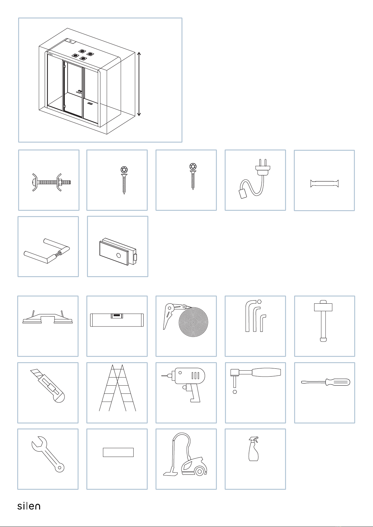
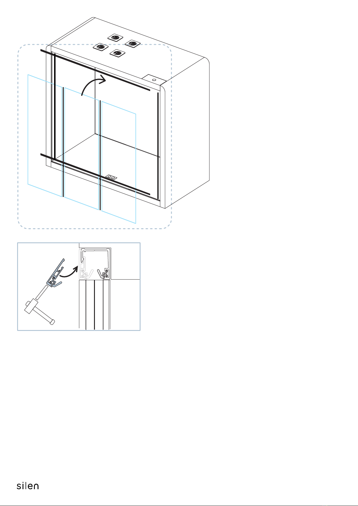
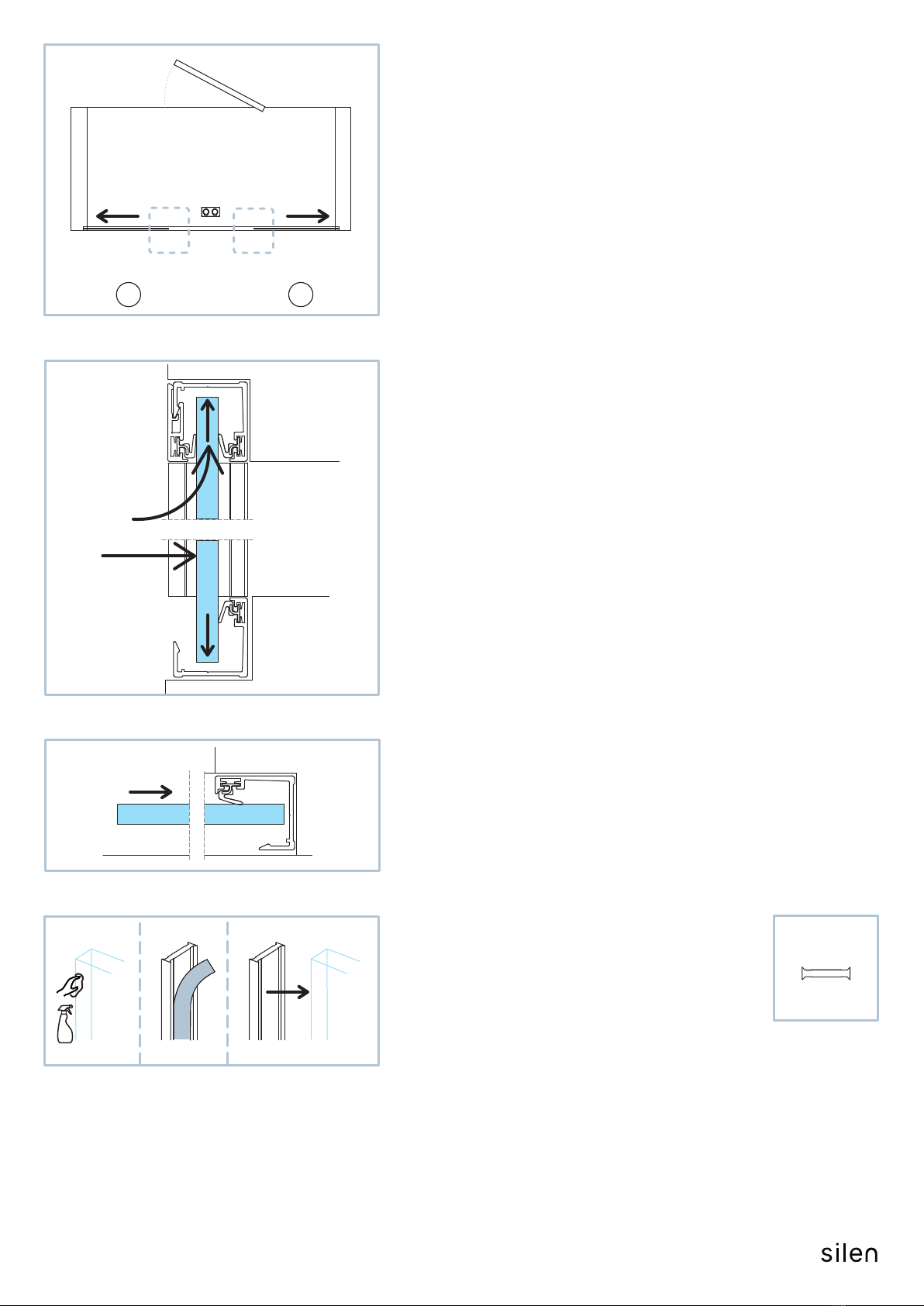
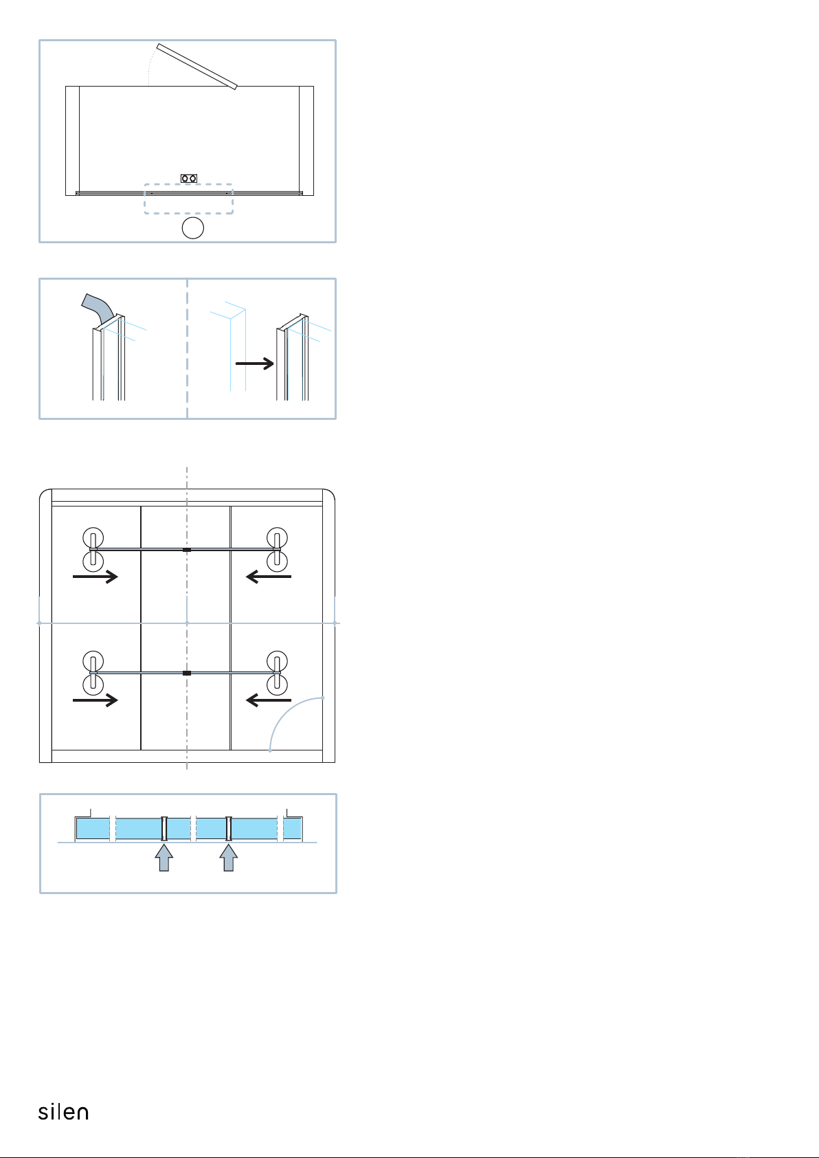
9.4 To add the middle back-glass panel:
Step 1. Clean the vercal edges of glass panel (L) with solvent
based soluon to remove any residue,
Step 2. Use sucon cups to posion the glass panel (L) into top
aluminum profile,
Step 3. Push the boom of the glass panel (L) towards the front
of the cabin,
Step 4. Carefully lower glass panel (L) unl it stands on spacers
pre-installed into boom aluminum profile,
Step 5. Remove the remaining glue covering strips from previously
aached glass-glass seals “c”,
Step 6. Aach four sucon cups on the side glass panels
(as shown on schemac 9.4).
Place ratcheng straps between the top and boom sucon
cups and ghten unl all panels are fixed to the glass-glass
seals while making sure the glass panels are on the same
plane to one another.
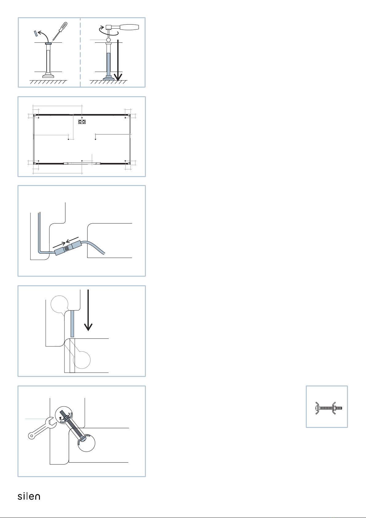
Note! Make sure the side module and floor module are
perpendicular to each other.
9

L L L
G1 G1
G2
G2
9.5
G2
9.6
A
G
9.5. Click in profile (G1) to the side modules using a rubber
mallet and plasc block to secure it.
Note! Slide the vercal profile (G1) up between the top
profile and side module.
9.6 Click in profile (G2) to the floor module using a rubber
mallet and plasc block to secure it.
10

G
G
10.
C
A
D
10.1
D
B
B
G2
G3
G3
G2
G1
G1
1.
2.
D
G
A
3.
10.2
10.3
C
G
10. Front glass panel and door frame installaon:
10. 1 Click in profile (G2) to the floor module using a rubber
mallet and plasc block to secure it.
10. 2 Place two front-glass panels (G) into the aluminum profiles:
Step 1. Li the glass panel (G) into the top aluminum profile
using sucon cups,
Step 2. Push the boom of the glass panel (G) towards the
back of the cabin,
Step 3. Carefully lower the glass panel (G) unl it stands on
spacers pre-installed into boom aluminum profile,
Step 4. Repeat with second glass panel on the opposite side.
10. 3 Shi the glass panels (G) right/le unl they reach the
boom of the aluminum profile on the side modules.
11

H
G G
A
B C
FRONT
BACK
a1 a1
H
10.5
d
A
1.
D
H
G2
10.4
10. 5 Drive in screws “d” to aach
the door frame (H) to the floor module.
10. 4 Install the door frame (H):
Step 1. Li the door frame (H) into the top aluminum profile,
Step 2. Push the boom of the door frame (H) towards the
back of the cabin,
Step 3. Lower the door frame (H) unl it stands on the
floor module.
Note! Make sure the door frame is
centered between the side modules.
H
G
G
C
D
T15
3,5x35mm
dx4
12

10.7
10.6
GG
H
90o
a1 a1
J
G1
G3 G3
H
G1
10. 6 Aach four sucon cups on the side glass panels
(as shown on schemac 10.6).
Place ratcheng straps between the top and boom sucon
cups and ghten unl both panels are slid into the door frame
profiles.
10. 7 Click in profile (G1) to the side modules using a rubber mallet
and plasc block to secure it.
Note! Make sure the side and floor module are perpendicular
to each other.
Note! Slide the vercal profile (G1) up between the top profile and
side module.
G3
10.8
A
G
10. 8 Click in two profiles (G3) to the floor module using a rubber
mallet and plasc block to secure them.
10.9
J
10. 9 Remove protecon tape from decorave door threshold (J).
HJ
10.10
A
10. 10 Aach threshold with glue covered side to door frame.
13

11.1
11.2
H
H
3mm
4mm
11.3
H
K
11.
H
K
K
INSIDE
OUTSIDE
NB!
11. Door glass installaon:
11. 1 Remove the covering plate from the hinges using a 3mm allen key
to unlock the pin.
11. 2 Use 4mm allen key to remove the securing plate from hinges.
11. 3 Use sucon cups to li door-glass panel (K)
to the hinges.
Note! Check if the door-glass panel (K) is straight.
If the glass has a curve to it, determine the
inside and outside by using a long straight
level tool.
14

Max 15Nm
11.4
11.4
11.5
11.6
H
4mm
K
K
K
H
H
H
11. 4 Door-glass panel (K) must be equally centered in
relaon to all four sides with approximate 6mm
gap between the glass and door frame.
11. 5 Fix the glass by aaching the securing plate back
on the hinges using a 4mm allen key.
11. 6 Reaach the covering plate on top of door frame hinges.
6mm
6mm
6mm
6mm
15

3mm
4mm
x1
x1
h
h
h
h
m
m
m
12.
12.1
12.3
12.2
Note! Before lock and handle installaon see
manual „Switching the handedness on a lock case“
12. Lock and handle installaon:
12.3 Use 4mm allen key to open the rest of the lock assembly “m”.
12.2 Aach the dedicated tool provided with lock assembly “m” to handle “h”
to remove the lock assembly “m” cover plates.
12.1 Use 3mm allen key to open the preassembled handle set “h”.
16

4mm
2mm
2mm
m
12.4
INSIDE
K
K
HNB!
NB!
12.4 Place the lock assembly “m” on door-glass and
secure bolts with 4mm allen key.
Note! Make sure part “m” is posioned at a 90-degree angle
in relaon with door-glass edge.
3mm
h
hh
m
m
12.5
12.6
INSIDE
INSIDE
K
K
12.5 Reaach the cover plates on lock assembly “m” using the
dedicated tool with handle “h”.
12.6 Aach handle “h” to lock assembly “m” using 3mm allen key.
Make sure the plasc fasteners are covered with provided
metal covers on both sides.
Note! Handle with the spindle must stay inside the cabin
for safety measures.
In case of emergency you must be able to open the door to exit.
17

13.
13.1
13.2
13.2
13.3
13.3
13.4
13.4
13.2
M N
N
R
P
NB!
1mm1mm
P
P
M
N
R
P
M
P
N
13. Covering trim installaon:
13.1 Aach engraved covering trim (R) on the front side of ceiling module.
13.2 Aach covering trims (P) on the front/back side of floor module and
back side of ceiling module.
13.3 Aach covering trim (M) on the front/back side of side module and
connect it with pins aached to part (R) and (P).
13.4 Aach covering trim (N) on the front/back side of side module and
connect it with pins aached to part (R) and (M).
18

A
5mm
min
A
A
14.
14.
A
14. To relocate the cabin, li up previously lowered
levelling glides and move it to desired locaon.
Repeat step 1. to secure the cabin again.
Note! Make sure to adjust all 8 glides
when in the final posion.
19
Other manuals for Space 2
1
Other silen Office Equipment manuals