<BLDC motor designed by SAESHIN’s own technology and know-how>
- Provide the optimized performance by BLDC motor and standard angle handpiece.
<Program Memory Function>
- Maximum 9 programmable memories for setting Speed, Gear Ratio, Torque, Rotating Direction and
Irrigation Pump.
<Automatic Overload Protection Function>
- The motor is automatically stopped and ‘Error’ sign display on screen when the load is higher than
Torque value.
- For releasing the overload function, release the foot controller.
<Realtime RPM, TORQUE View System>
- Actual RPM and Torque value are displayed on the screen. It makes user can do more delicate operation.
<Motor Auto-calibration Function>
- Motor auto-calibration function is that control box check the angle handpiece status to reconcile speed
and torque that user wants with angle handpiece for accurate and safe operation.
1. Set the program number at ‘0’. The program changes to calibration mode.
2. Push the foot controller to the end. The calibration starts and the display show the calibration process.
3. During normal operation, the calibration will be completed after 5~10 seconds with ‘-CAL-’ on the screen
and beep sounds.
4. When it is completed, Use the product.
<Ergonomic Foot Controller>
- Foot controller is designed ergonomically to control all the functions. And it provides high convenience.
<Optic Function - (option)>
- LED: 25,000 Lux
- Optic function is only operated by Optic angle handpieces (TRAUS CRB26LX, TRAUS CRB27LX,
TRAUS CRB46LN) and Optic micro motor(TRAUS MBP10SL).
PRODUCT FEATURES & ADVANTAGES
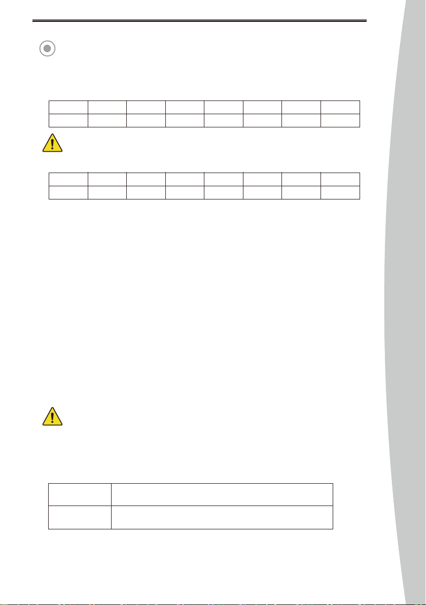
1:4
160,000rpm200,000rpm40,000rpm2,500rpm2,000rpm 1,480rpm
1:51:116:1 20:127:1
1,250rpm
32:1
620rpm
64:1
- RPM :
- Torque :
- Gear Ratio: 1:4, 1:5, 1:1, 16:1, 20:1, 27:1, 32:1, 64:1
- LED: 25,000 Lux
The free-running speed of the handpiece shall be in accordance with the manufacturer’s instructions
at a tolerance of ±10 % as specified. (Refer to ISO 14457)
- The function is set up when the product is released by manufacturer and Use the function when
user repair or change the product.
- Program 0 is the only for auto-calibration function, so the memory function or other setting value
does not work.
1:4
**N·cm**N·cm **N·cm 5~50N·cm 5~70N·cm 5~80N·cm
1:51:116:1 20:127:1
5~80N·cm
32:1
5~80N·cm
64:1
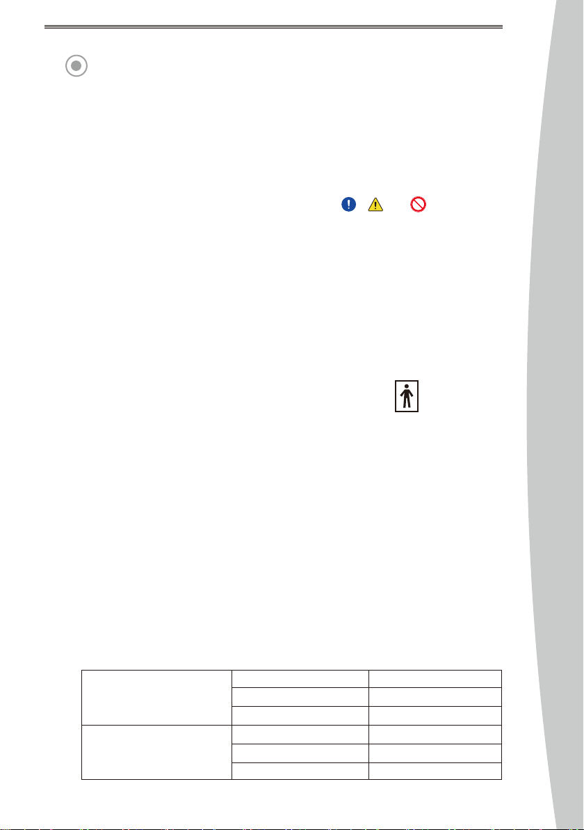
Basic Components TRAUS MBP10SX + Non-Optic Angle Handpiece : Except Optic Function
TRAUS MBP10SL + Optic Angle Handpiece : Optic FunctionOption
8