BE Power Equipment 30 WHIRL-A-WAY User manual

User Manual
30” WHIRL-A-WAY
85.403.030
85.403.031
85.403.032
BEPOWEREQUIPMENT
.COM

2

3
TABLE OF CONTENTS
Introduction
4 Using the Manual
Product Identification
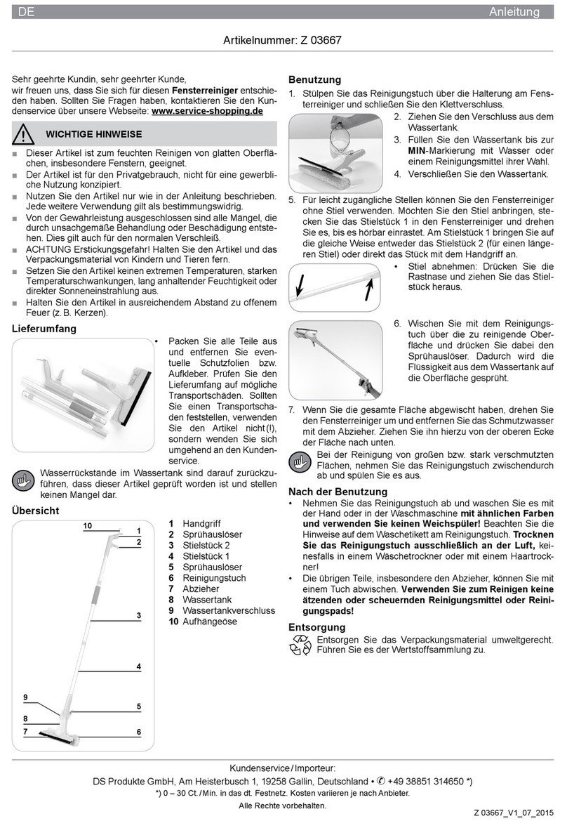
5 Product Identification (Whirl-A-Way)
Operating Instructions
6 Set Up
7 Operation
Parts Diagram & List (85.403.030)
8 Parts Diagram
9 Parts List
Parts Diagram & List (85.403.031)
10 Parts Diagram
11 Parts List
Parts Diagram & List (85.403.032)
12 Parts Diagram
13 Parts List

4
Using the Operator’s manual
The operating manual is an important part of your Whirl-A-Way. It should
be read thoroughly before initial use and referred to often to make sure
adequate safety and service concerns are being addressed.
Reading the owner’s manual thoroughly will help avoid any personal injury
or damage to your pump. The information in this manual will offer you the
most effective tools for cleaning as well as the safest. By knowing how
best to operate this machine you will be better positioned to show others
who may also operate the unit.
This manual contains information for the complete range of BE 30” Whirl-
A-Ways, and is placed in order starting from the safety requirements to
the operating functions of your pump. You can refer back to the manual at
any time to help troubleshoot any specific operating functions, so store it
with the machine at all times.
Attention: Read through the complete manual
prior to the initial use of your Whirl-A-Way.
INTRODUCTION

5
Record Identification Numbers
Whirl-A-Way
If you need to contact an Authorized Dealer or Customer Service line
(1-866-850-6662) for information on servicing, always provide the
product model and identification numbers.
You will need to locate the model and serial number for the pump and
record the information in the places provided below.
For information on warranty and to register your product online,
please visit BEPOWEREQUIPMENT.COM
Date of Purchase:
Dealer Name:
Dealer Phone:
Product Identification Numbers
Model Number:
Serial Number:
PRODUCT IDENTIFICATION

6
Set-Up
1. Fit the lower portion of the handle into the mounting brackets on the
cover and secure with the bolts or the pins & clips.
2. Next, tighten the “fixed” hose end into the gun mounted onto the upper
portion of the handle. Use teflon tape on the hose ends.
3. Once this is complete, join the two sections of the handle together and
secure with the bolt or the pin & clip. Tighten the swivel end of the
hose into the top of the rotary head.
4. Turn the cover over and check to ensure that the nozzle tips are
securely tightened and the spray pattern is in line with the rotary arm.
5. It is important to adjust and tighten the rotary head so the rotary arm
spray tips are a minimum of 1” distance from the surface being
cleaned.
Operation
The Surface Cleaning System you have purchased connects directly
to your high pressure hose and pressure washer by means of quick
couplers, operating to a maximum of 4000 PSI.
This Whirl-a-Way is designed to operate with both hot & cold water
pressure washers. We do not recommend the use of hot water as the
nylon brush skirt will soften and wear prematurely, voiding any warranty.
We recommend that you supply grease to the rotary head every 30 – 40
hours of use.
During operation, should you experience a buildup of small stones or
other foreign material within the cover, simply tip the cleaner on its side at
45° . This should expel any foreign materials and will give longer wear to
your tips and swivel arm.
The tips that have been installed on your surface cleaning system permit
the use of your cleaner with a pressure washer producing up to 7 GPM
at 4000 PSI. Higher GPM tips should be installed if your pressure
washer has a higher GPM/PSI rating. Periodically check the tips to
ensure they are not plugged by dirt particles.
OPERATING INSTRUCTIONS

7
It is very important when operating your Whirl-a-Way that you maintain
a continuous motion. Should you leave the cleaner in a stationary
position, the surface being cleaned can be seriously damaged by the
high pressure. The distance of the nozzle tips from the surface can be
adjusted by loosening the bolt on the rotary head mounting collar and
adjusting the rotary head up or down. Be certain the allen head bolt is
tightened again to prevent the rotary head from moving during operation.
Please ensure that your rotary head is adjusted to maintain a minimum of
1” clearance between the spray tips and the surface being cleaned.
While operating your surface cleaning system, please ensure that the
nylon brush skirt remains in contact with the surface being cleaned. Do
not operate on vertical or overhead surfaces. We strongly recommend
that safety eye goggles, gloves and work boots be worn when operating
this Whirl-a-Way. Keep hands and feet away from the high pressure,
high speed rotating arm that is protected by the plastic cover.
Should your surface cleaner not be used for long periods of time, it is
recommended that you remove the hose from the top of the rotary head
and a vegetable oil be used to lubricate the swivel head’s internal parts.
Manually turn the rotary arm to allow lubrication of all internal parts before
storing.
You will quickly find your surface cleaning system a welcome addition to
your pressure washing applications. It is designed to give you a safe
and rapid method for cleaning hard surfaces, and will save you time in
comparison to using a conventional gun and wand. The durability of
this surface cleaning system is enhanced by the way it is handled by
the operator. Please take care to ensure that the Whirl-A-Way is not
continuously being swung against buildings, curbs, etc., which can
damage the cover. Also, be aware that the high speed rotating arm
must not come in contact with rigid protruding objects which can quickly
damage or completely break off the steel arm. Finally, do not apply
excessive weight to the plastic cover as it could break the cover.
OPERATING INSTRUCTIONS

8
85.403.030
PARTS DIAGRAM

9
85.403.030
PARTS LIST
REF # BE PART NUMBER DESCRIPTION
36,27,23,28 85.792.047 BRUSH SKIRT & HARDWARE
31 85.792.059 COVER
21 85.792.046 CASTOR
20,32 85.792.100 CASTOR BRACKET(4)& HARDWARE(8)
15 85.790.004 ROTARY HEAD
38,39 85.792.101 ROTARY ARMS
33,32,34,26,25,24,46,47,48,49,41 85.792.110 WATER BROOM
2,4,5,6,7,8,9,12,13,14,22,23,32,45 85.792.103 HANDLE KIT
18,19 85.792.104 HANDLE BRACKET X 2
17, 16 BF4044 MI-T-M COLLAR
7,8,45 85.792.105 GUN MOUNT ADAPTER
43,44,40 85.792.111 VALVE KIT

10
85.403.031
PARTS DIAGRAM

11
85.403.031
PARTS LIST
REF # BE PART NUMBER DESCRIPTION
36,27,23,28 85.792.047 BRUSH SKIRT & HARDWARE
31 85.792.059 COVER
21 85.792.046 CASTOR
20,32 85.792.100 CASTOR BRACKET(4)& HARDWARE(8)
15 85.790.004 ROTARY HEAD
38,39 85.792.101 ROTARY ARMS
33,32,34,26,25,24 85.792.102 WATER BROOM
2,4,5,6,7,8,9,12,13,14,22,23,32,40 85.792.103 HANDLE KIT
18,19 85.792.104 HANDLE BRACKET X 2
17, 16 BF4044 MI-T-M COLLAR
7,8,40 85.792.105 GUN MOUNT ADAPTER

12
85.403.032
PARTS DIAGRAM

13
85.403.032
REF # BE PART NUMBER DESCRIPTION
29,26,18,25 85.792.047 BRUSH SKIRT AND HARDWARE
21 85.792.059 COVER
23 85.792.046 CASTOR
24,25,22 85.792.106 CASTOR BRACKET & HARDWARE
16 85.790.004 ROTARY HEAD
30,31 85.792.101 ROTARY ARMS
1,2,3,4,5,6,7,17,18,24,10,32 85.792.107 HANDLE KIT
19,20 85.792.104 HANDLE BRACKET X2
14 BF4044 MI-T-M COLLAR
3,4,32 85.792.105 GUN MOUNT ADAPTER
PARTS LIST

If you need assistance with the assembly
or operation of your Whirl-A-Way please call
1 - 866 - 850 - 6662
THE POWER YOU NEED.

Si vous avez besoin d’assistance avec
l’assemblage ou l’opération de Whirl-A-Way,
s’il vous plait appelez le
1 - 866 - 850 - 6662
THE POWER YOU NEED.

COMPOSANTES DE LA GÉNÉRATRICE
85.403.032
REF # BE PART NUMBER DESCRIPTION
29,26,18,25 85.792.047 BRUSH SKIRT AND HARDWARE
21 85.792.059 COVER
23 85.792.046 CASTOR
24,25,22 85.792.106 CASTOR BRACKET & HARDWARE
16 85.790.004 ROTARY HEAD
30,31 85.792.101 ROTARY ARMS
1,2,3,4,5,6,7,17,18,24,10,32 85.792.107 HANDLE KIT
19,20 85.792.104 HANDLE BRACKET X2
14 BF4044 MI-T-M COLLAR
3,4,32 85.792.105 GUN MOUNT ADAPTER

COMPOSANTES DE LA GÉNÉRATRICE
85.403.032

85.403.031
COMPOSANTES DE LA GÉNÉRATRICE
REF # BE PART NUMBER DESCRIPTION
36,27,23,28 85.792.047 BRUSH SKIRT & HARDWARE
31 85.792.059 COVER
21 85.792.046 CASTOR
20,32 85.792.100 CASTOR BRACKET(4)& HARDWARE(8)
15 85.790.004 ROTARY HEAD
38,39 85.792.101 ROTARY ARMS
33,32,34,26,25,24 85.792.102 WATER BROOM
2,4,5,6,7,8,9,12,13,14,22,23,32,40 85.792.103 HANDLE KIT
18,19 85.792.104 HANDLE BRACKET X 2
17, 16 BF4044 MI-T-M COLLAR
7,8,40 85.792.105 GUN MOUNT ADAPTER
COMPOSANTES DE LA GÉNÉRATRICE

85.403.031
COMPOSANTES DE LA GÉNÉRATRICE

85.403.030
11
COMPOSANTES DE LA GÉNÉRATRICE
REF # BE PART NUMBER DESCRIPTION
36,27,23,28 85.792.047 BRUSH SKIRT & HARDWARE
31 85.792.059 COVER
21 85.792.046 CASTOR
20,32 85.792.100 CASTOR BRACKET(4)& HARDWARE(8)
15 85.790.004 ROTARY HEAD
38,39 85.792.101 ROTARY ARMS
33,32,34,26,25,24,46,47,48,49,41 85.792.110 WATER BROOM
2,4,5,6,7,8,9,12,13,14,22,23,32,45 85.792.103 HANDLE KIT
18,19 85.792.104 HANDLE BRACKET X 2
17, 16 BF4044 MI-T-M COLLAR
7,8,45 85.792.105 GUN MOUNT ADAPTER
43,44,40 85.792.111 VALVE KIT
COMPOSANTES DE LA GÉNÉRATRICE
Table of contents


