BeaconMedaes MEGA 2 Manual

Part No. 6-847684-00 Rev. D01 Pg. 1
MEGA 2
®
Medical Electronic Gas Alarm
Installation, Operation, and Maintenance Instructions
MAN 01-027

2Part No. 6-847684-00 Rev. D01
Table of Contents
Introduction
Alarm Modular Components...............................................................................4
Definitions...........................................................................................................5
Alarm Configuration............................................................................................6
Unpacking ..............................................................................................................7
Rough-In Installation
Alarm Panel Back Box Mounting........................................................................8
Remote Sensor Back Box Mounting ..................................................................9
Pipeline Connection
Sensor Module .............................................................................................9
Pressure Switch..........................................................................................10
Wiring Installation
General Requirements......................................................................................11
Wire Type and Size ..........................................................................................11
Wire Routing Inside The Alarm Panel ..............................................................11
Determining Number Of Conductors................................................................12
Wiring Schematics............................................................................................13
Alarm Wiring Examples ....................................................................................13
Finish Installation
Line Voltage Electrical Connection...................................................................27
Front Panel Installation.....................................................................................27
Sensor Installation
Remote Sensors.........................................................................................28
Local Sensors.............................................................................................29
Remote Sensor Wiring .....................................................................................29
Source Equipment Wiring.................................................................................30
Field Wiring Cable Shield Grounding ...............................................................31
Building Automation System Wiring
Multi-Signal Module Relays........................................................................32
Digital Display Module High/Low Relays....................................................32
Annunciator Module General Fault Relay ..................................................32
Annunciator Module Auxiliary Relay (optional)...........................................32
Johnson Controls METASYS® System......................................................33
Slave Panel Wiring ...........................................................................................33

3
Part No. 6-847684-00 Rev. D01
Table of Contents
Operation
Start-Up and Checking .....................................................................................34
Set-Up Procedure
Digital Display Module................................................................................35
Multi-Signal Module....................................................................................38
Monitoring Mode
Digital Display Module................................................................................40
Multi-Signal Module....................................................................................41
Testing
Digital Display Module......................................................................................41
Multi-Signal Module..........................................................................................42
Power Supply Module ......................................................................................43
Troubleshooting Guide ........................................................................................45
Replacement Parts
Front Panel Components .................................................................................50
Back Box Components.....................................................................................51
Sensor Components.........................................................................................52
Field Installation Kits.........................................................................................53

4Part No. 6-847684-00 Rev. D01
Annunciator Module
Features:
• User interface
pushbuttons for alarm
panel TEST function,
audible alarm MUTE
and set-up increase
!and decrease ".
• Green alarm panel
POWER ON and red
audible alarm mute
indicators.
• Audible alarm with
volume control.
• Network wiring terminals and test
connector.
• General fault relay that activates on any
alarm panel fault condition.
Alarm Modular Components
Introduction
Digital Display Module
Features:
• Digital LED readout
of system pressure
signal transmitted
from sensor module.
• Adjustable
brightness of digital
LED readout.
• Individual LED’s indicate when system
pressure/vacuum is HIGH (red), LOW
(red), or NORMAL (green).
• Programmable high and low alarm
thresholds.
• Adjustable audible alarm mute duration.
• Individual high and low alarm dry-contact
relay outputs.
• Can transmit pressure or vacuum signal to
another digital display module for remote
applications.
• Can be networked to communicate with a
personal computer or Johnson Controls
Metasys® building automation
system(using Metasys Integrator).
Multi-Signal Module
Features:
• Monitors up to five
normally closed dry-
contact switch
signals.
• Separate indicators
for each of five
signals for normal
(green) or abnormal (red) conditions.
• Available (optional) with separate dry-
contact relay outputs for each of five
signals.
• Can be networked to communicate with a
personal computer or Johnson Controls
Metasys® building automation system
(using Metasys Integrator).
Blank Module
Features:
• Reserves a space in
alarm panel for
future expansion.
• Used to fill unused
alarm panel module
locations.

5
Part No. 6-847684-00 Rev. D01
Definitions
Area Alarm Panel
Alarm panel that monitors medical gas and
vacuum systems serving a specific area.
Auxiliary Fault Relay (optional)
A single-pole double-throw dry-contact relay
output located on annunciator module. Used
to activate a remote alarm or building
management system. The relay will activate
whenever ANY audible alarm on panel is in
progress. Pressing MUTE button on
annunciator module deactivates relay until
audible alarm is again reactivated. Relay
contact ratings are 2 A @ 30 VDC/0.5 A @
125 VAC.
Dry-Contact
An electrical contact that is isolated or
unconnected from any electrical source.
General Fault Relay
A single-pole double-throw dry-contact relay
output located on annunciator module. Used
to activate a remote alarm or building
management system. The relay will activate
whenever ANY audible alarm on panel is in
progress. Unlike Auxiliary Fault Relay,
pressing MUTE button on annunciator
module WILL NOT deactivate relay. The
General Fault Relay will deactivate only after
alarm condition is corrected and alarm panel
resumes normal status. Relay contact ratings
are 2 A @ 30 VDC/0.5 A @ 125 VAC.
LED
Light Emitting Diode
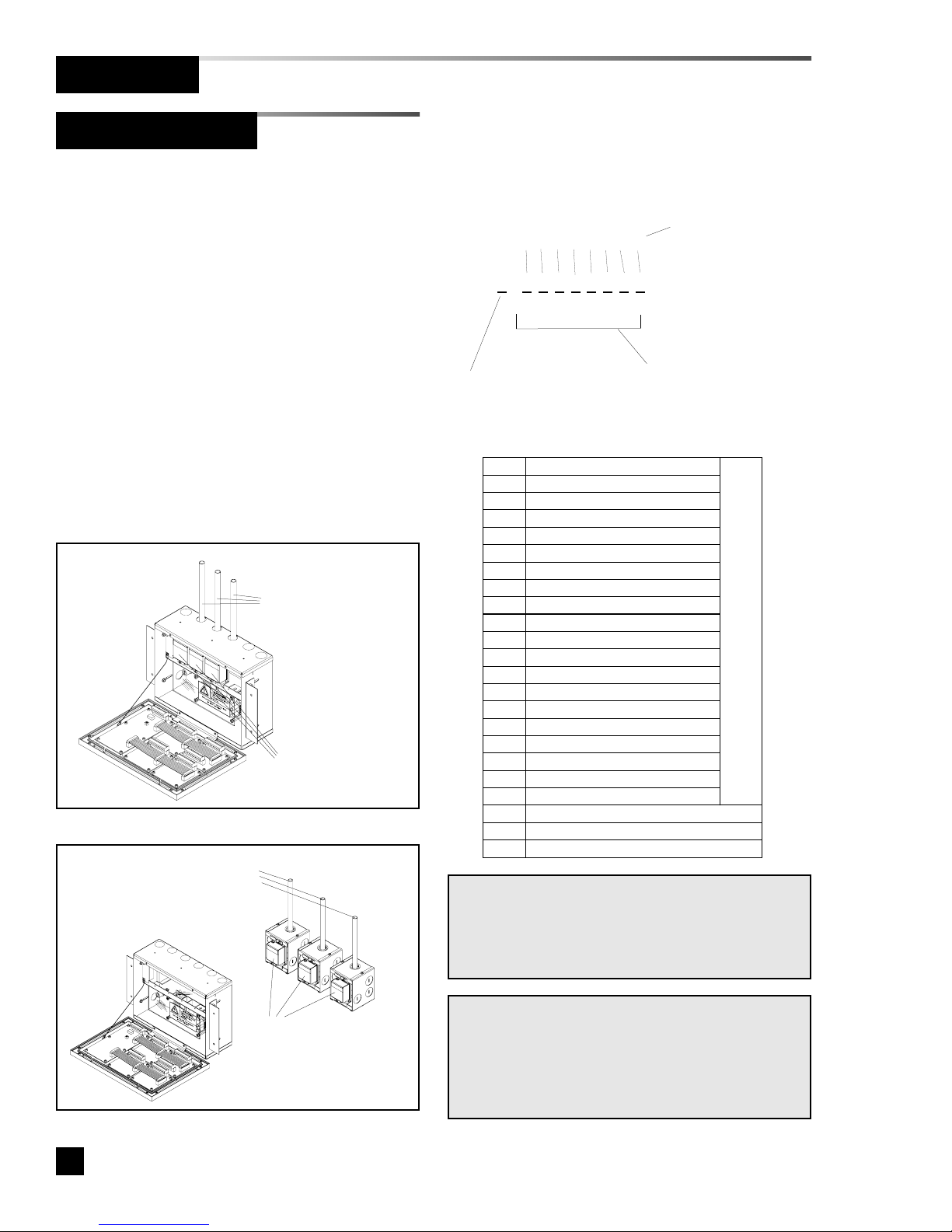
Local Sensors
Pressure/vacuum sensors that are mounted
inside alarm panel box. The sensor rough-in
must be piped to medical gas/vacuum
pipelines.
Master Alarm Panel
Alarm panel that monitors medical gas and
vacuum source equipment and main pipelines.
Remote Sensors
Pressure/vacuum sensors that are mounted
outside of alarm panel box. Sensor rough-ins
may be mounted separately or ganged together
near pressure/vacuum pipelines. Sensors must
then be wired to alarm panel.
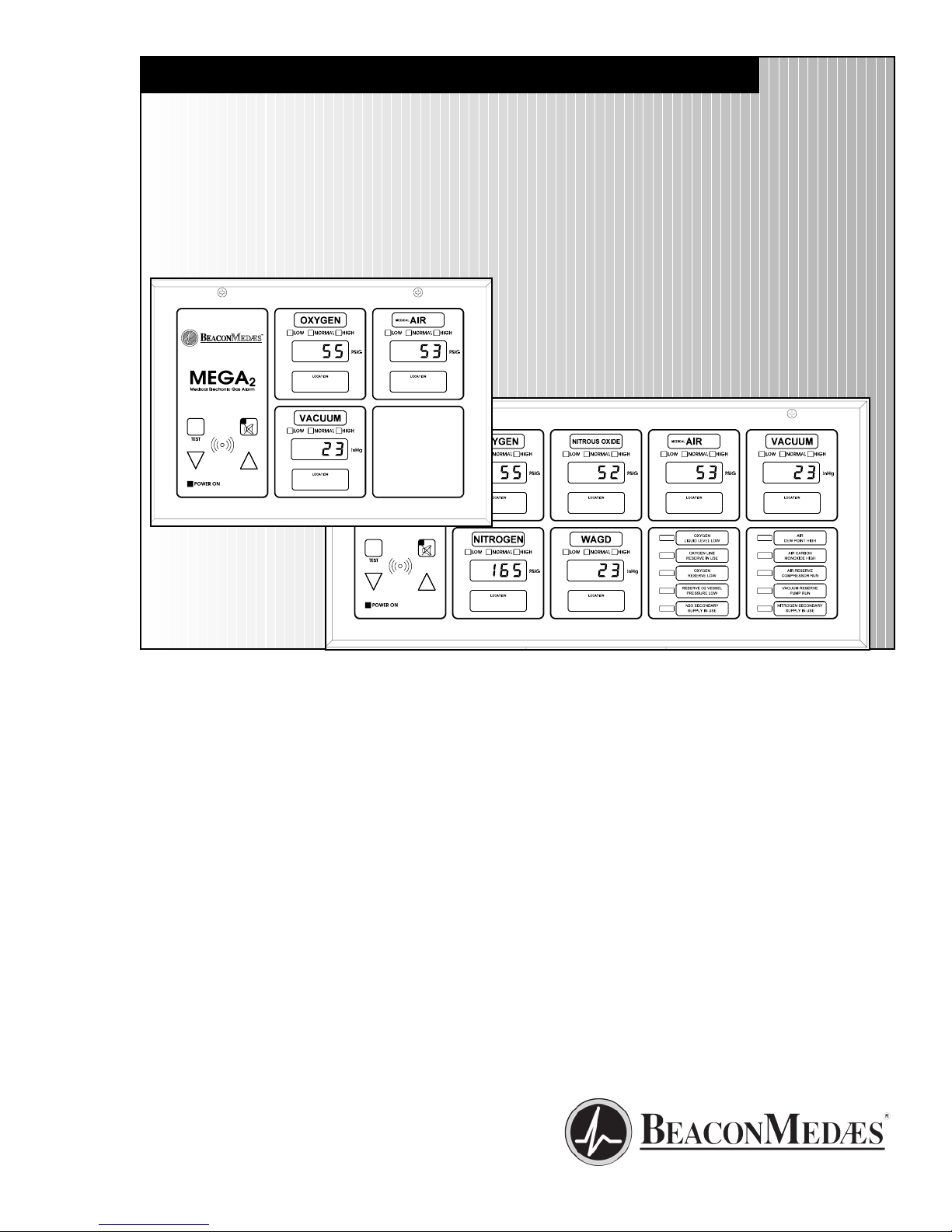
All MEGA2 alarm panels are factory pre-
configured. The configuration of alarm panel
varies dependent upon customer’s
requirements.
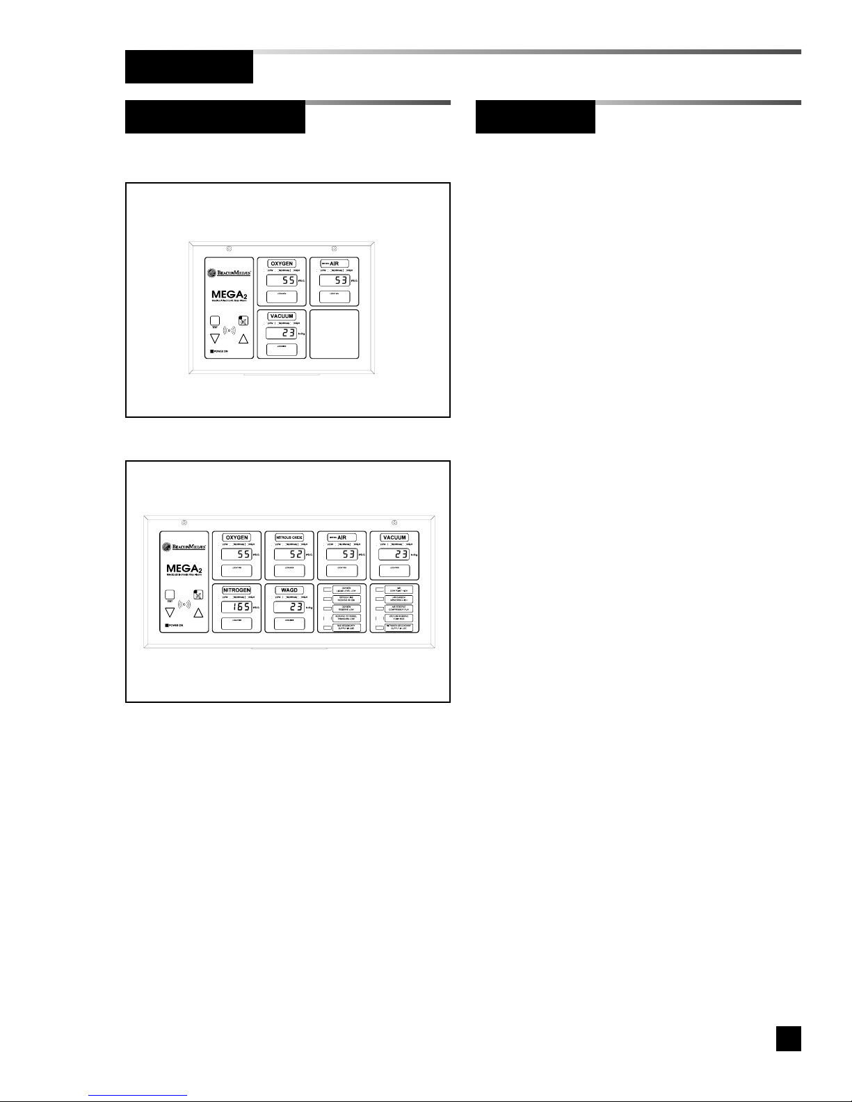
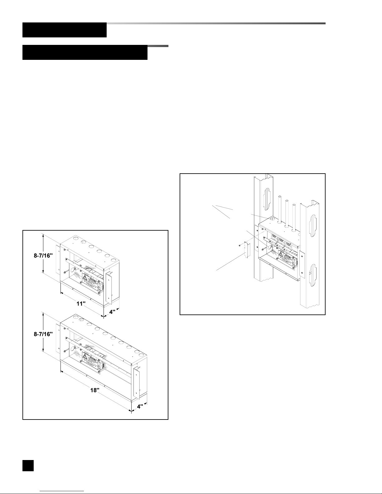
Two sizes of alarm panels are available. The
small alarm panel (Figure 1) will accommodate
an annunciator module with four alarm
modules. The large alarm panel (Figure 2) will
accommodate an annunciator module with
eight alarm modules.
Figure 1: Four Module Panel
Figure 2: Eight Module Panel
Alarm Configuration
Introduction

6Part No. 6-847684-00 Rev. D01
Alarm Configuration
Introduction
An alarm panel may consist of any
combination of digital display modules, multi-
signal modules, or blank modules.
If alarm panel is configured with digital display
modules, pressure/vacuum sensors will be
included for connection to pressure/vacuum
pipeline (except for 6-M2N).
Sensors may be located inside alarm panel
rough-in box (local sensors) or outside alarm
panel rough-in box (remote sensors).
Local sensors must be connected to
pressure/vacuum pipelines via copper tubing
(Figure 3). Remote sensor may be mounted
near pressure/vacuum pipeline and then wired
to alarm panel (Figure 4).
The required alarm panel configuration may be
specified within the part number scheme as
described below:
Part Number Scheme:
6-M2 ?-? ? ? ? ????
Figure 3: Local Sensors
Figure 4: Remote Sensors
1 2 3 4 5 6 7 8 Position within alarm
panel (Figures 1 and 2)
L = Local Sensors
R = Remote Sensors
N = No Sensors
(Slave Applications)
Designates type of
alarm panel component
from chart below
O
OXYGEN
D
OXYGEN - 100 PSI
X
NITROUS OXIDE
A
MEDICAL AIR
F
MEDICAL AIR - 100 PSI
5
AIR (ISO)
7
LABORATORY AIR
2
O2-CO2
4
O2-He
C
CARBON DIOXIDE
G
CARBON DIOXIDE - 100 PSI
1
CO2-O2
3
He-O2
H
HELIUM
V
VACUUM
6
VACUUM (ISO)
8
LABORATORY VAC
W
WAGD
N
NITROGEN
9
INSTRUMENT AIR
DIGITAL DISPLAY MODULES
M
MULTI-SIGNAL MODULE
R
MULTI-SIGNAL MODULE W/ RELAYS
B
BLANK
Sensor modules are
mounted inside the
alarm panel box
Copper tubes connect to
pressure/vacuum
pipelines
Sensors have separate
mounting boxes for mounting
near pressure/vacuum
pipeline and then must be
wired to alarm panel
Copper tubes connect to
pressure/vacuum
pipelines NOTE:
When an alarm panel is ordered with either local
or remote sensors, ALL sensors will either be
local or remote. Alarm panels with a combination
of local and remote sensors are not available.
NOTE:
Alarm panel components in table above are listed
in order of criticality. Unless otherwise specified,
the most critical component will fill position one,
the next less critical component will fill position
two, etc. etc.

7
Part No. 6-847684-00 Rev. D01
Introduction
Alarm Configuration
Example: P/N 6-M2R-OAVB
Example: P/N 6-M2R-OXAVNWMM
Unpacking
1. Remove alarm panel back box from
shipping carton. Do not remove alarm
front panel (wrapped in anti-static
shipping bag).
2. If alarm panel is configured with
remote sensors, remove sensor
rough-in and mounting box from small
individual boxes shipped within main
alarm panel shipping carton.
3. Store all other components not
removed in steps 1 and 2 inside
shipping carton in a safe place for
installation later.
4. Install back box and sensor rough-in
as described in this manual.

8Part No. 6-847684-00 Rev. D01
Rough-In Installation
The alarm panel back box will be one of
two sizes. The height and depth of both
size boxes are the same. Refer to Figure
5 below for dimensions of both boxes.
If alarm panel is configured with digital
display modules, sensor assemblies will
be included for connection to
pressure/vacuum pipeline.
Sensors may be located inside alarm
panel rough-in box (local sensors) or
outside alarm panel rough-in box (remote
sensors).
If equipped with local sensors, copper
tubes will extend from top of back box to
be connected to pressure/vacuum
pipeline.
Figure 5: Alarm Panel Back Box Dimensions
Alarm Panel Back Box Mounting
1. Prepare a rough wall opening large
enough to accommodate alarm panel
back box. Alarm panel back box must
have rigid vertical members for
support on both left and right sides.
Power to alarm panel shall enter
through lower left or top left conduit
hole in back box.
2. Remove cardboard dust cover and
insert alarm panel back box into wall
opening. Secure with fasteners
suitable for vertical supports as shown
in Figure 6.
3. Mounting brackets on each side of
back box are adjustable and factory
preset for 5/8” thick drywall. After
drywall installation, front edge of back
box should be flush with finished
surface of wall. If needed, make any
necessary bracket adjustments at this
time. Refer to Figure 7.
4. Reinstall cardboard dust cover.
Figure 6: Back Box Mounting
Two choices of
conduit holes for
entrance of AC
mains power
Small box - (four modules)
Large box - (eight modules)
top entry
side entry
For top entry, remove
shield for access.
Reinstall shield after
connection is made

9
Part No. 6-847684-00 Rev. D01
Figure 7: Mounting Bracket Adjustment
Rough-In Installation
Pipeline Connection
Figure 8: Remote Sensor Back Box
Sensor Module
1. Braze copper extension tubes from
sensor rough-in to appropriate
pressure/vacuum piping system drops
as shown in Figure 9. Braze
connections per procedures required
by NFPA 99 or CAN/CSA-Z305.1.
Use appropriate measures to prevent
overheating and damage to internal
components of sensor rough-in
assemblies.
2. Perform standing pressure tests and
cross connection tests as required by
NFPA and CSA.
Loosen screws to
adjust back box depth
(same each side)
Four holes in back of box are
provided for surface mounting
Alarm panels ordered with remote
sensors are provided with separate metal
boxes for each sensor. Mount each
sensor box as follows:
1. Remove sensor rough-in from
mounting box (Figure 8).
2. Using four mounting holes provided,
attach box to a wall or other structural
support. (fasteners by others).
3. Reinstall sensor rough-in.
Rear conduit knockouts
(either side) are recommend-
ed for sensor wiring
Alarm Panel Back Box Mounting
Remote Sensor Back Box Mounting

10 Part No. 6-847684-00 Rev. D01
Rough-In Installation
Pipeline Connection
Pressure Switch
DISS (Diameter Index Safety System)
connection kits are recommended for use
when attaching pressure switches to
pressure/vacuum pipeline. To utilize
these kits, a 1/4-18 NPT female thread
must be provided in piping system. All
necessary components are included in
each gas specific kit as shown in Figure
10.
Figure 10: Pressure Switch Pipeline Connection
DISS Kit P/N Gas Service
6-120004-10 Oxygen
6-120004-11 Nitrous Oxide
6-120004-12 Medical Air
6-120004-13 Vacuum
6-120004-14 Nitrogen
6-120004-18 Instrument Air
6-120004-19 Evac. (WAGD)
6-120004-20 Carbon Dioxide
6-120004-21 CO2/O2
6-120004-22 O2/CO2
6-120004-23 He/O2
6-120004-24 O2/He
6-120004-25 Helium
To pipeline
To pressure switch
DISS male
body
with check
DISS nut
and nipple
Figure 9: Sensor Pipeline Connection
Connection
should be made
on top of pipe
Horiz. run of pipeline
Connection
should be made
on top of pipe
REMOTE SENSOR
LOCAL SENSOR

11
Part No. 6-847684-00 Rev. D01
Wiring Installation
• Power all alarms from life safety
branch of emergency power system as
required by applicable standards.
• Protect all wiring from physical
damage by raceways or conduit as
required by applicable standards.
• Wire master panels directly to
switches or sensors as required by
applicable standards.
• Wiring runs should be made with color
coded wire. Record color, signal, and
source of signal for each wiring lead to
aid in connection of alarm finish
components.
• Avoid installing alarm panels near
radio transmitters, electrical motors, or
switchgear.
Figure 11: Wire Routing
General Requirements
Wire Type And Size
Wire Routing
Holes for entrance of
low voltage field wiring
All low voltage MEGA2 wiring must meet
the following criteria:
• Copper wire no smaller than 22 AWG.
• Circuit length not to exceed 5000 feet.
• Cable must be twisted pair shielded
type. Multi-pair cables within one
common shield are acceptable.
Two 7/8” holes are provided for entrance
of AC mains power. One hole on lower
left side and one hole on top left of alarm
panel back box. NO OTHER HOLES
SHOULD BE PUNCHED OR USED. If
hole on top left is used, remove shield for
access. Reinstall shield after connection
is made.
Several additional 7/8” holes are provided
on right side of top panel for entrance of
low voltage field wiring. Refer to Figure
11.
Two choices of
conduit holes for
entrance of AC
mains power
top entry
side entry
For top entry, remove
shield for access. Reinstall
shield after connection is
made

12 Part No. 6-847684-00 Rev. D01
Wiring Installation
MEGA2 alarm panels can be ordered in
numerous configurations. The following
rules along with references to this
manual’s schematics clarify wiring
requirements.
• All alarm panels require 100 to 250
VAC 50/60 Hz. power. Refer to
Wiring Schematic 1 (Pg. 14).
• Sensor modules send
pressure/vacuum signals to digital
display modules. If the alarm panel
configuration contains digital display
modules and sensor modules that are
remotely mounted, two conductors are
required between EACH sensor
module and digital display module. A
sensor module can not be wired to
more than one digital display module.
Refer to Wiring Schematic 2 (Pg. 15).
• Multi-signal modules monitor signals
from dry normally closed switch/relay
contacts. These signals can originate
at source equipment or from pressure
switches mounted on main
pressure/vacuum pipelines. When two
master alarms are required, the same
switch/relay contacts can be wired to
both alarm panels. Two conductors
are required for each alarm panel for
each signal. That is, for any given
signal, two wires will route to first
alarm panel and another two wires will
route to second panel. Both pairs of
wires will originate from switch/relay
contacts. This wiring is duplicated for
each source equipment/pressure
switch signal. Refer to Wiring
Schematics 3 and 8 (Pgs. 16 and
20).
Determining Number Of Conductors
• Two panels may be connected
together so digital display module
pressure reading(s) of first panel will
be duplicated at second panel. Two
conductors for EACH digital display
module must be routed from first
alarm panel to second alarm panel.
Refer to Wiring Schematic 4 (Pg. 17).
• If an alarm panel is to be connected to
a Johnson Controls METASYS®
system, two conductors must be
connected between alarm panel’s
annunciator module and monitoring
system’s two-wire data bus. Refer to
Wiring Schematic 9 (Pg. 21).
• Most building automation systems are
capable of monitoring dry normally
closed relay contacts. If alarm panel
is to be connected to this type of
building automation system, two
conductors must be routed from alarm
panel to building automation system
for each signal monitored. Refer to
Wiring Schematics 5,6, and 7 (Pgs.
18 and 19).

13
Part No. 6-847684-00 Rev. D01
Wiring Schematics Alarm Wiring Examples
Wiring Installation
The wiring schematics listed below are
provided. Call BeaconMedæs at 1-888-
4MEDGAS (1-888-463-3427), for technical
support .
1. Power Supply Module
2. Sensor Module to Digital Display
Module
3. Multi-Signal Module
4. Remote Pressure/Vacuum
Transmission
5. Multi-Signal Module Relays
6. General Fault/Auxiliary Relays
7. Digital Display Module High/Low Relays
8. Remote Pressure/Vacuum Switches
9. Johnson Controls METASYS®
Wiring examples of master/area alarms for
the following systems are provided:
1. Two master alarm panels with digital
displays - high-pressure manifold/no
reserve (oxygen shown) - Pg. 22.
2. Two master alarm panels with digital
displays - liquid manifold/high-pressure
reserve (oxygen shown) - Pg. 23.
3. Two master alarm panels with digital
displays - liquid bulk/liquid reserve
(oxygen shown) - Pg. 24.
4. Two multi-signal master alarm panels -
duplex air compressor and vacuum
pump systems - Pg. 25.
5. Area alarm panel - gas services for
oxygen, medical air, and vacuum - Pg.
26.

14 Part No. 6-847684-00 Rev. D01
Wiring Schematic 1: Power Supply Module
Annunciator Module
20-wire ribbon cable
to adjacent module
20-wire ribbon cable
to adjacent module
Power Supply
Fuse Holder
Ground (green)
Line (black)
Neutral (white)
3-wire power supply harness
120V AC Mains Power Connections
Ground
Screw
Red
Orange
Black
Red
Orange
Black

15
Part No. 6-847684-00 Rev. D01
Wiring Schematic 2: Sensor Module to Digital Display Module
Digital Display Module
Digital Display Module Remote sensor mounting box
(remote from alarm panel)
Local sensor
(inside alarm panel back box)
2-pin polarized connector
ribbon to
adjacent
module
LOCAL SENSOR
REMOTE SENSOR
ribbon to
adjacent
module
*Sensor pigtail
Sensor pigtail
(provided)
Wire nuts
Field wiring
(by others)
*NOTE:
Sensor pigtails for local sensors
are factory connected to digital dis-
play module.
Pin 5 - red (+)
Pin 6 - black (-)
Pin 5 (+)
Pin 6 (-)
NOTE:
Field wiring cable shields must be grounded at
only one end, inside alarm panel back box. Refer
to page 31 for details.

16 Part No. 6-847684-00 Rev. D01
Wiring Schematic 3: Multi-Signal Module
SIGNAL 1
SIGNAL 2
SIGNAL 3
SIGNAL 4
SIGNAL 5
Dry normally-closed
contacts at source
equipment or line
pressure switches
COM +
COM +
COM +
COM +
COM +
ribbon to
adjacent
module
ribbon to
adjacent
module
Pin 1
Pin 10 Pin 1
Pin 10
Multi-Signal Module
at FIRST master alarm
panel
Multi-Signal Module
at SECOND master alarm panel
SIGNAL 1 - pin 1 (+), pin 2 (COM)
SIGNAL 2 - pin 3 (+), pin 4 (COM)
SIGNAL 3 - pin 5 (+), pin 6 (COM)
SIGNAL 4 - pin 7 (+), pin 8 (COM)
SIGNAL 5 - pin 9 (+), pin 10 (COM)
NOTE:
Installer assigns source signals to desired front panel locations
and installs provided labels (Refer to Figure 23, page 31).
Multi-Signal Module front panel
NOTE:
Field wiring cable shields must be grounded at
only one end, inside alarm panel back box. Refer
to page 31 for details.

17
Part No. 6-847684-00 Rev. D01
Wiring Schematic 4: Remote Pressure / Vacuum Transmission
Digital Display Module
at master alarm panel
Digital Display Module
at slave alarm panel
Signal from
sensor module
Pin 5 (+)
Pin 6 (-)
Master output
to slave
Pin 4 (-) / Pin 3 (+)
Slave input
from master
Pin 1 (+)
Pin 2 (-)
ribbon to
adjacent
module
ribbon to
adjacent
module
NOTE:
The above master to slave wiring configuration DOES NOT comply with NFPA 99
wiring guidelines for two required master panels. In order to comply, EACH mas-
ter panel must be directly connected to a Sensor Module for each pressure/vacu-
um service. Additional panels, if desired, may be connected as indicated above.
NOTE:
Field wiring cable shields must be grounded at
only one end, inside alarm panel back box. Refer
to page 31 for details.

18 Part No. 6-847684-00 Rev. D01
Wiring Schematic 5: Multi-Signal Module Relays (Optional)
SIGNAL 1
SIGNAL 2
SIGNAL 3
SIGNAL 4
SIGNAL 5
Dry normally-closed
contacts at source
equipment or line
pressure switches
COM +
COM +
COM +
COM +
COM +
Multi-Signal Module
ribbon to
adjacent
module
SIGNAL 1 - pins 1 & 2
SIGNAL 2 - pins 3 & 4
SIGNAL 3 - pins 5 & 6
SIGNAL 4 - pins 7 & 8
SIGNAL 5 - pins 9 & 10
Dry normally-closed output
relay contacts
NOTE:
Output relay contacts are dry normally closed type. Contacts open
upon designated alarm activation. Contacts remain open until
alarm condition is corrected. Alarm mute DOES NOT affect relay
condition.
Relay contact ratings are 2 A @ 30 VDC/0.5 A @ 125 VAC
.
NOTE:
Field wiring cable shields must be grounded at
only one end, inside alarm panel back box. Refer
to page 31 for details.

19
Part No. 6-847684-00 Rev. D01
Wiring Schematic 6: General Fault / Auxiliary Relays
Wiring Schematic 7: Digital Display Module High / Low Relays
Annunciator Module
Digital Display Module
ribbon to
adjacent
module
General Fault Relay
N/C (pin 5)
N/O (pin 3)
Common (pin 4)
N/O (pin 6)
Common (pin 7)
N/C (pin 8)
Auxiliary Relay NOTE:
General Fault Relay activates when ANY
alarm on panel is in progress. Pressing
MUTE on Annunciator Module DOES
NOT reset relay. Relay deactivates when
alarm condition is corrected.
Auxiliary Relay (optional) activates when
ANY audible alarm on panel is in progress.
Pressing MUTE on Annunciator Module
WILL deactivate relay until audible alarm is
again reactivated.
Relay contact ratings are 2A @ 30 VDC/0.5
A @ 125 VAC.
ribbon to
adjacent
module
Low Alarm Relay
N/C (pin 8)
Common (pin 7)
N/C (pin 10)
Common (pin 9)
High Alarm Relay NOTE:
High Alarm Relay activates when high line
pressure alarm on digital display module is
in progress. When relay activates normally
closed contacts open. Pressing MUTE
on Annunciator Module DOES NOT deacti-
vate relay. Relay deactivates when high line
pressure alarm condition is corrected.
Low Alarm Relay activates when low line
pressure alarm on digital display module is
in progress. When relay activates normally
closed contacts open. Pressing MUTE
on Annunciator Module DOES NOT deacti-
vate relay. Relay deactivates when low line
pressure alarm condition is corrected.
Relay contact ratings are 2A @ 30 VDC/0.5
A @ 125 VAC.

20 Part No. 6-847684-00 Rev. D01
Wiring Schematic 8: Remote Pressure / Vacuum Switches
P/N 6-129020-01 (Dual switch for medical gases with 50 PSI nominal pressure)
P/N 6-129021-01 (Dual switch for medical gases with 175 PSI nominal pressure)
P/N 6-129022-01 (Single switch for vacuum)
1/4 NPT female port
1/4 NPT
female port
seven - approx. 18” free leads
through 3/4” conduit connection
terminal strip
1/2” conduit
connection
ground
screw
low
high
adjustment
dials
high
low high
yellow
brown*
orange*
purple*
red*
blue
(N/C)
(N/C)
(N/O)
(N/O)
(C)
(C)
NOTE:
Switch contacts shown with
50 PSI pressure applied.
Low switch is
preset at 40 PSI.
High switch is preset at 60
PSI.
*Wires/contacts to be used with MEGA2 alarm system
adjustment
screws
NOTE:
Switch contacts shown with 20
inHg vacuum applied.
Low switch is
preset at 12 inHg.
green
ground
low low high
yellow
brown*
orange*
purple*
red*
blue
(N/C)
(N/C)
(N/O)
(N/O)
(C)
(C)
NOTE:
Switch contacts shown with 175
PSI pressure applied.
Low switch is
preset at 140 PSI.
High switch is preset at 190 PSI.
*Wires/contacts to be used with MEGA2 alarm system
1/4 NPT female port
four - approx. 18” free leads
through 3/4” conduit connection
low
adjustment
dial
*Wires/contacts to be used with MEGA2 alarm system
low
purple*
red*
blue
(N/C)
(N/O)
(C)
green
ground
P/N 0208-5096-300 (Single switch for medical gases with 175 PSI nominal pressure)
1/4 NPT male port
three - approx. 12” free leads
through 1/2” NPT conduit connection
adjustment
sleeve
NOTE:
2 Switches Required.
Switch contacts shown
with 175 PSI pressure
applied.
Switch is preset at 195
PSI increasing.
Installer must set low
switch to 140 PSI
decreasing.
*Wires/contacts to be used with MEGA2 alarm system
low
purple*
red*
blue
(N/C)
(N/O)
(C)
high
purple*
red
blue*
(N/C)
(N/O)
(C)
Table of contents
Other BeaconMedaes Security System manuals