BeaconMedaes Area Line Pressure Alarm Manual

For Parts or Technical Assistance 0178-1737-000 Rev. A
Technical Support: 1-888-4MEDGAS (463-3427)
Customer Service: 1-888-4MEDGAS (463-3427)
www.beaconmedaes.com
Area Line
Pressure
Alarm
OPERATION & MAINTENANCE MANUAL
Product No. 0321

HEADER
20178-1737-000 Rev. A
TABLE OF CONTENTS
User Responsibility . . . . . . . . . . . . . . . . . . . . . . . . . . 1
Cross Connection Prevention . . . . . . . . . . . . . . . . . . 1
Precautions . . . . . . . . . . . . . . . . . . . . . . . . . . . . . . . . . 1
1/Introduction . . . . . . . . . . . . . . . . . . . . . . . . . . . . . . . 2
2/General Information
2.1 Description . . . . . . . . . . . . . . . . . . . . . . . . . . . . . . . 2
2.2 Dry Contact Relays . . . . . . . . . . . . . . . . . . . . . . . . 2
2.3 Specifications . . . . . . . . . . . . . . . . . . . . . . . . . . . . . 2
3/Set-Up and Operation
3.1 Pre-Use Checkout . . . . . . . . . . . . . . . . . . . . . . . . . 4
3.2 Controls and Indicators . . . . . . . . . . . . . . . . . . . . . 4
4/Operator Maintenance
4.1 Repair Policy . . . . . . . . . . . . . . . . . . . . . . . . . . . . . 5
4.2 General Maintenance . . . . . . . . . . . . . . . . . . . . . . 5
4.3 Testing Switch Gauges . . . . . . . . . . . . . . . . . . . . . 6
Warranty . . . . . . . . . . . . . . . . . . . . . . . . . . . . . . . . . . . . 9
Cross Connection Prevention
After installation, perform a pipeline system check to cer-
tify that there are no cross connections, in accordance
with National Fire Protection Association 99.
User Responsibility
This Product will perform in conformity with the descrip-
tion thereof contained in this operating manual and accom-
panying labels and/or inserts, when assembled, operat-
ed, maintained and repaired in accordance with the
instructions provided. This Product must be checked peri-
odically. A defective Product should not be used. Parts
that are broken, missing, plainly worn, distorted or conta-
minated should be replaced immediately. Should such
repair or replacement be come necessary,
BeaconMedæs recommends that a telephonic or written
request for service advice be made to BeaconMedæs.
This Product or any of its parts should not be repaired
other than in accordance with written instructions provid-
ed by BeaconMedæs and by BeaconMedæs trained per-
sonnel. The product must not be altered without the prior
written approval of BeaconMedæs The user of this
Product shall have the sole responsibility for any mal-
function which results from improper use, faulty mainte-
nance, improper repair, damage, or alteration by anyone
other than BeaconMedæs.
PRECAUTIONS
Warnings
After installation of an alarm panel, make absolutely cer-
tain that the alarms are correctly connected to their
respective gas lines in accordance with NFPA 99.
Do not use liquid cleaning solutions on this unit. Liquid
solutions may enter the unit and cause system damage or
present an electric shock hazard. See Page 5.
The “Testing the Switch Gauges” procedure requires a
change of switch gauge trigger points during the test.
Readjust the alarm trigger points after completing this
procedure. See Page 6.
Caution
No repair should ever be under taken or attempted by
anyone not having general experience in the repair of
devices of this nature. See Page 5.
HEADER
0178-1737-000 Rev. A 3
1/INTRODUCTION
2/GENERAL INFORMATION
This manual gives the recom-
mended operating instructions
for the BeaconMedæs Area
Line Pressure Alarm Panel.
Every procedure listed is per-
formable by the operator of this
equipment. For service informa-
tion, refer to the BeaconMedæs
Area Line Pressure Alarm Panel
Service Manual.
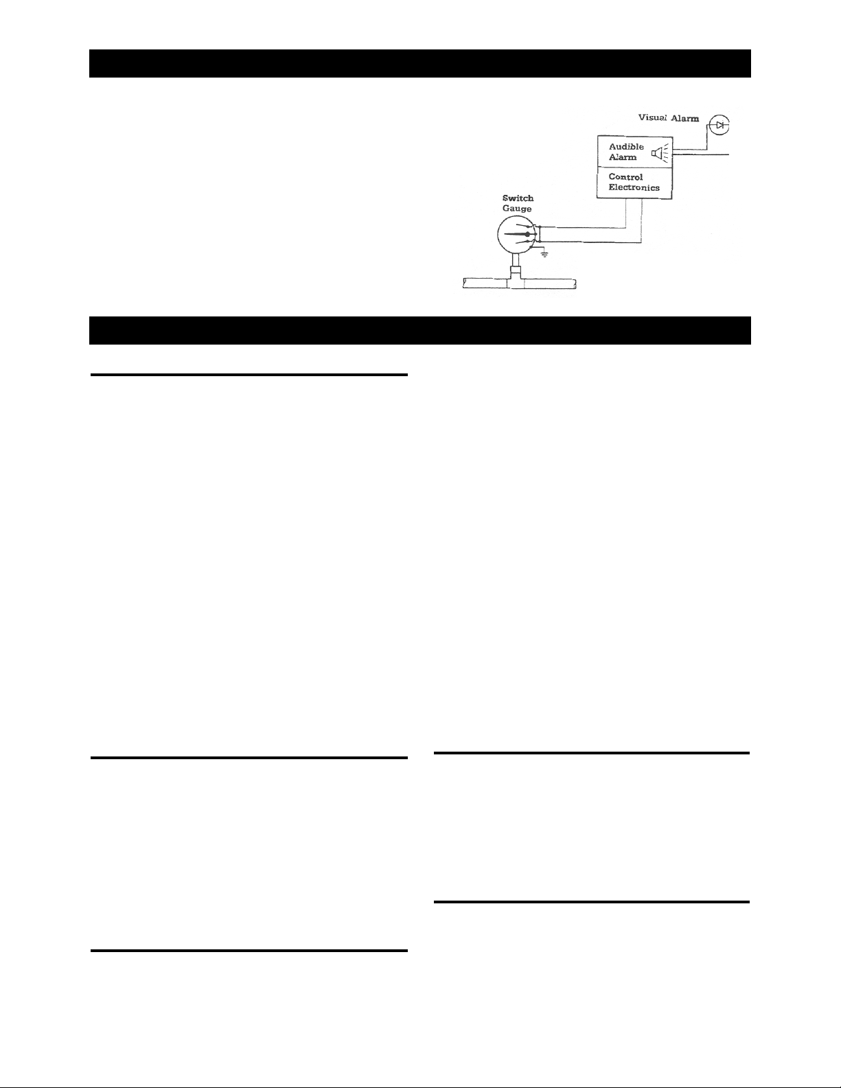
Figure 1
Area Alarm Circuit
2.1 Description
The area line pressure alarm panel is a wall mounted unit
that monitors the gas pressure (or vacuum) in up to six
separate lines and sounds an alarm if preset limits are
violated (Figure 1).
One panel holds up to six gauges. Each gauge is labeled
with a color-coded label for the gas it monitors. In the
event of an alarm, a red indicator (labeled ABNORMAL)
glows next to the gauge for the affected gas (Figure 2).
Each switch gauge is wired in a closed loop: if a wire
breaks, or is disconnected from the circuit board or
switch, the alarm panel sounds an alarm (Figure 3).
The panel has a test switch that exercises the electronics
assembly. Remove the louvered panels to test the switch
gauges. This means that the unit can be tested for func-
tionality without major disassembly or special test equip-
ment.
Use only approved service procedures and genuine
replace ment parts for repairs. Complete service informa-
tion and a list of available replacement parts are provided
in the Service Manual.
2.2 Dry Contact Relays
The alarm panel contains seven dry contact relays for
interface to remote equipment. The connection to these
relays is made at the circuit board. One relay indicates
normal conditions; the other six will indicate alarm condi-
tions.
These relays can operate as normally open or normally
closed switches depending on how the connections are
made. Refer to the installation instructions or service
manual for the wiring diagram.
2.3 Specifications
Gases Monitored: From one to six of the following gases
can be monitored. O2, N2O, N2, AIR, CO2, VAC, EVAC.
Dimensions
Alarm Panel:
14 in. x 9 3/4 in.
(35.6cm x 24.6cm)
Enclosure (rough-in box):
12 5/8 in. x 8 3/8 in. x 3 5/8 in.
(32.5cm x 21.3cm x 9.5 cm)
Color Coding
Standard, USA color coded labels for all readouts.
Optional Canadian and ISO color coded labels available.
Power Requirements
Standard 120 V~, 60 Hz, 25 watts (max.)
Export Only 220 V~, 50 Hz, 25 watts (max.)
Note: The 120 V~ model is listed by Underwriters
Laboratories. The 220 V~ model has not been investi-
gated.
Leakage Current
Less than 100 uA
Circuit Type
Closed loop-alarm on ground contact or open circuit
Control Unit
Microprocessor-Motorola 6805 Series
Gauge Accuracy:
Gas Indicating Gauge Switch Gauge
Nominal 50 psi ±2 psi (25-75 psi) ±2 psi (33-66 psi)
Medical Gases ±3 psi elsewhere ±3 psi elsewhere
Nominal 180 psi ±6 psi (75-225 psi) ±6 psi (100-200 psi)
Gas ±9 psi elsewhere ±9 psi elsewhere
Vacuum Switch ±.6 in. Hg
(7.5-22.5 in. Hg) ±.6 in. Hg (10-20 in. Hg)
±.9 in. Hg elsewhere ±.9 in. Hg elsewhere
Gauge Overpressure Limit
Indicating Gauge Switch Gauge
Oxygen 110 psig 150 psig
Nitrous Oxide 110 psig 150 psig
Air 110 psig 150 psig
Carbon Dioxide 110 psig 150 psig
Nitrogen 330 psig 400 psig
Vacuum (Do not pressurize) 45 psig
Note: If line pressure should fall or rise to
set alarm limits the gauge needle will
interrupt current flow and cause an alarm
condition.

HEADER
40178-1737-000 Rev. A
2/GENERAL INFORMATION
Figure 2
Six Gas Area Alarm Panel
Figure 3
Closed Loop Configuration
Note: If break in line should occur
the path will be interrupted causing
an alarm condition.
Switch Gauge Operation (NORMAL): The gauge pointer
moves in response to change in gas line pressure. Under
normal pressure conditions, the pointer will not be in con-
tact with the gauge alarm contacts.
Switch Gauge Operation (ABNORMAL): As gas line
pressure goes to an abnormal (high or low) level, the
pointer will move accordingly. Once the pointer touches
one of the contacts, the normal (5V) signal will be inter-
rupted and an alarm condition will be sensed by the control
elements.

HEADER
0178-1737-000 Rev. A 5
2/SETUP AND OPERATION
3.1 Pre-Use Checkout
WARNING: After installation of an alarm panel, make
absolutely certain that the alarms are correctly con-
nected to their respective gas lines.
After the builder has installed the alarm panels, they must
be tested for potential cross connections, in accordance
with NFPA 99. Only qualified service personnel are capa-
ble of performing this test.
3.2 Controls and Indicators
(Figure 5)
Alarm Silence - Press this button to silence the alarm.
The alarm remains silenced unless a new alarm condition
occurs. If multiple abnormal conditions exist, the alarm
will continue to sound until all have been corrected.
Te s t - P r e s s t h i s b u t t o n t o t e s t t h e e l e c t r o n i c s o f t h e
panel. When this button is pressed, the NORMAL and all
the ABNORMAL lights should glow. The alarm tone
should sound.
Normal - This green light glows when all of the gas pres-
sures and vacuum levels are within preset limits. It turns
off when an abnormal pressure, vacuum level or system
failure is detected.
Abnormal - When this indicator glows next to a pressure
gauge, it means that the gas pressure or vacuum is out-
side the preset limits. An alarm tone also sounds when-
ever one of these lights comes on. Once the abnormal
condition is rectified, the alarm automatically resets,
unless other alarm conditions exist.

HEADER
60178-1737-000 Rev. A
4/OPERATOR MAINTENANCE
4.1 Repair Policy
Note: Service, other than what is described in this manu-
al, must be performed by a “Technically Competent” indi-
vidual as described in the Service Manual for this product.
Do not use malfunctioning equipment. Make all neces-
sary repairs, or have the equipment serviced by an
Authorized BeaconMedæs Service Representative. After
repair, test the equipment to ensure that it is functioning
properly, in accordance with the manufacturer’s published
specifications .
To ensure full reliability, have all repairs and service done
by an Authorized BeaconMedæs Service Representative.
If this cannot be done, replacement and maintenance of
those parts listed in this manual may be undertaken by a
competent, trained individual having experience in the
repair of devices of this nature.
CAUTION: No repair should ever be undertaken or
attempted by anyone not having general experience
in the repair of devices of this nature.
Replace damaged parts with components manufactured or
sold by BeaconMedæs. Then test the unit to ascertain that it
complies with the manufacturer's published specifications.
Contact BeaconMedæs Technical Support for service
assistance. In all cases, other than where
BeaconMedæs’s warranty is applicable, repairs will be
made at BeaconMedæs’s current list price for the replace-
ment part(s) plus a reasonable labor charge.
4.2 General Maintenance
The alarm panel is designed to provide extended service life
with a minimum of maintenance. All of the indicators use
light emitting diodes (LEDs). Once a month, test these
indicators and the electronics by pressing the TEST
switch (Figure 5). If the alarm tone does not sound, or if
an indicator does not light up, have the panel repaired by
a qualified service person. The indicator lights are not
intended to be replaced by the operator. Once a year
have a qualified service person verify the accuracy of the
alarm trigger points.
Keep the panel clean by wiping it off with a soft, dry
cloth. Do not scrub the panel with abrasive or liquid
cleansers, or with liquid sterilizing agents.
WARNING: Do not use liquid cleaning solutions on
this unit. Liquid solutions may enter the unit and
cause system damage or present an electric shock
hazard.
Figure 5
Controls and Indicators
HEADER
0178-1737-000 Rev. A 7
4/OPERATOR MAINTENANCE
4.3 Testing the Switch Gauges
Use the following procedure to test the switch gauge cir-
cuitry. See Figures 6 through 8.
WARNING: This procedure requires a change of pres-
sure switch settings during the test. Readjust the alarm
trigger points after completing this procedure.
Tools required:
!#2 Phillips screwdriver
!1/16 hex wrench
!Transparent tape
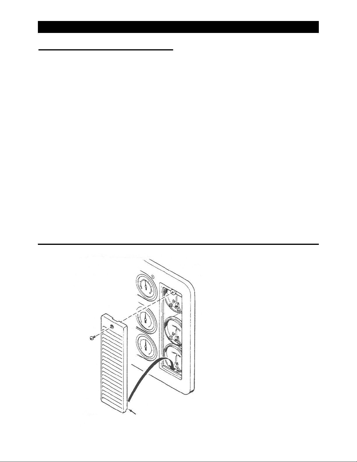
1. Remove the left and right louvered panels by remov-
ing the Phillips head screws located at the top of each
panel (Figure 6).
2. Verify that the readings indicated on each switch
gauge and the associated line pressure gauge match
to within:
6 psig for the nominal 50 psi gases, 18 psig for the 180
psi gases and 2 inches Hg. for the vacuum system.
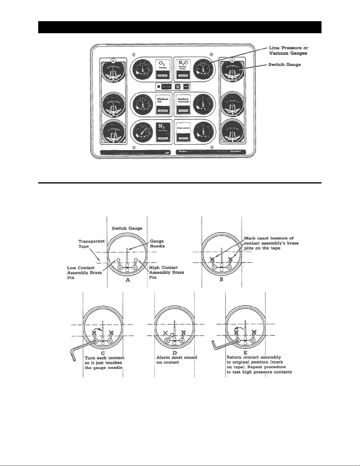
3. Place a suitable length of transparent tape across the
face of each switch gauge. The tape should be long
enough so that the ends of the tape clear the front
panel (Figure 8).
4. Mark the exact location of the contact assembly’s
brass pins on the transparent tape (Figure 8B).
5. Using the 1/16 hex wrench individually turn each low
(left side) contact so it just touches the gauge needle
(Figure 8C).
6. The alarm must sound on contact. If no alarm
sounds, the panel needs repair (Figure 8D).
Note: If remote alarms or monitors are connected, these
devices will be activated.
7. Return each contact assembly to its original position
(mark placed on transparent tape. (Figure 8E).
8. Repeat steps 5 through 7 to test high (right side)
pressure contacts.
9. Remove tape and reattach the louvered access panels.
Note: This test only checks switch gauge electronics; it
does not verify alarm trigger points. If the switch gauge
trigger points require adjustment, refer to the section
“Setting Alarm Trigger Points” in the Service Manual.
Figure 6
Louvered Panel Removal
Note: Lip on louvered panel not shown.
When replacing, make sure lip is properly
positioned.
HEADER
80178-1737-000 Rev. A
4/OPERATOR MAINTENANCE
Figure 7
Gauge Location
Note: Each line pressure or vacuum gauge has a corre-
sponding switch gauge.
Figure 8
Pressure Switch Testing
Note: For clarity, shorting bars are not shown.

BeaconMedæs warrants the Area Line
Pressure Alarm to be free of defects in
materials or workmanship when installed
and operated in accordance with instruc-
tions. The warranty period is 30 months
from shipment date or 24 months from
startup, whichever period terminates
earlier.
This warranty covers all necessary parts
and labor required for correction of the
defect whether by any or all of repair,
replacement, or credit, which election
shall be made by BeaconMedæs at it's
sole discretion.
This warranty requires the owner to
ensure that the equipment is
1) started up or placed in service by an
authorized representative of
BeaconMedæs, 2) certified in accor-
dance with NFPA 99, most recent edi-
tion, by a properly qualified certification
agency, and 3) maintained in strict
accordance with Operation and
Maintenance Instructions provided with
the product.
Warranty claims will be honored only
after examination by BeaconMedæs and
only when such examination shall dis-
close to BeaconMedæs's reasonable
satisfaction that such equipment has not
been damaged in shipment or installa-
tion, improperly installed, operated out-
side of any published
operating limits (including but not limited
to temperature, pressure, humidity, or
ventilation), improperly
or inadequately maintained, field modi-
fied in any way, improperly repaired, or
in any other way improperly applied or
used.
All claims against this warranty require
prompt notification, within the warranty
period, of any seeming defect. Failure to
promptly notify BeaconMedæs of the
seeming defect will invalidate all war-
ranties.
This warranty excludes damage or
defect caused by shipping, acts of God,
fire, war, labor difficulties, action of gov-
ernment, or other cause beyond the rea-
sonable control of BeaconMedæs.
This warranty is given in lieu of all other
warranties, expressed or implied, includ-
ing implied warranties of fitness for a
particular purpose and merchantability.
In no event shall BeaconMedæs be
liable for damages in excess of the
value of the defective product, nor shall
BeaconMedæs be liable for any direct,
special or consequential damages, loss
of profit of any kind, or for loss of use of
the products.
0178-1737-000 Rev. A 9
WARRANTY

©2004 BeaconMedæs. All rights reserved.
Part No. 0178-1737-000 Rev. A
Table of contents
Other BeaconMedaes Security System manuals
Popular Security System manuals by other brands


Bulldog Security
Bulldog Security PRO-SERIES 5002 Installation and owner's guide

Alarm Lock
Alarm Lock PG30 installation instructions

ADEMCO
ADEMCO Vista Series 4120EC user manual

Notifier
Notifier 1010 Installation and programming manual

Bosch
Bosch Security Escort SE2000 Series Training manual

DMP Electronics
DMP Electronics CELLCOMSL SERIES Programming guide


