BeaconMedaes TotalAlert 2 Manual

Installation, Operation, and Maintenance Instructions
6-847718-00 Rev. B00


1
6-847718-00 Rev. B00
Introduction
Product Identification......................................................................................................4
Alarm Modular Components...........................................................................................5
Annunciator Module .................................................................................................5
Multiplexer Module ...................................................................................................5
LED Module..............................................................................................................5
Breakout Board ........................................................................................................5
Relay Board..............................................................................................................6
Digital Display Module..............................................................................................6
Multi-Signal Module..................................................................................................6
Blank Module............................................................................................................6
Definition of Statements .................................................................................................7
Definitions.......................................................................................................................7
Alarm Configurations....................................................................................................10
Master Alarms.........................................................................................................11
Area Alarms............................................................................................................12
Combo Alarms........................................................................................................14
Electromagnetic Compatibility ......................................................................................16
FCC ........................................................................................................................16
ICES-003................................................................................................................16
EN 60601-1-2 .........................................................................................................16
Installation Overview
Master Alarms ........................................................................................................21
Area Alarms............................................................................................................21
Combo Alarms........................................................................................................22
Installation Procedures
Rough-In.......................................................................................................................23
Alarm Panel Back Box ...........................................................................................23
Remote Sensor Back Box ......................................................................................24
Pipeline Connection ...............................................................................................25
Pull Wire .......................................................................................................................27
General Requirements ...........................................................................................27
Wire Type And Size................................................................................................27
Wire Routing...........................................................................................................28
Determining Number Of Conductors......................................................................29
Wiring ...........................................................................................................................30
Power Supply .........................................................................................................30
Remote Sensor ......................................................................................................31
Breakout Board Inputs............................................................................................32
Relay Board Outputs..............................................................................................33
Multi-Signal Module Inputs.....................................................................................34
Digital Display Module Master/Slave......................................................................35
Multi-Signal Module Relays....................................................................................35
General Fault / Aux Relays ....................................................................................36
Digital Display Module High / LowRelays ..............................................................36
Ethernet..................................................................................................................37
Building Automation System ..................................................................................37
Contents

26-847718-00 Rev. B00
Contents
Field Wiring Cable Shield Grounding.....................................................................39
Finish............................................................................................................................40
Front Panel Mounting.............................................................................................40
Local Sensor ..........................................................................................................41
Remote Sensor ......................................................................................................42
Labeling..................................................................................................................43
Wiring Schematics
Wiring Schematic 1: Power Supply.............................................................................46
Wiring Schematic 2: Sensor Module to Digital Display Module..................................47
Wiring Schematic 3: Multiplexer / Breakout Boards....................................................48
Wiring Schematic 4: Relay Board ...............................................................................49
Wiring Schematic 5: Multi-Signal Module Inputs.........................................................50
Wiring Schematic 6: Digital Display Module Master/Slave .........................................51
Wiring Schematic 7: Multi-Signal Module Relay Outputs ...........................................52
Wiring Schematic 9: Digital Display Module High / Low Relays ..................................53
Wiring Schematic 8: General Fault / Auxiliary Relays ................................................53
Wiring Schematic 10: Remote Pressure / Vacuum Switches .....................................54
Wiring Schematic 11: Johnson Controls Metasys® N2 Connection ...........................55
Operation
Start-Up and Checking .................................................................................................56
Master Alarm Panel................................................................................................56
Area Alarm Panel ...................................................................................................57
Combo Alarm Panel ...............................................................................................58
Set-Up Procedures.......................................................................................................59
Annunciator Module ...............................................................................................59
Multiplexer Module .................................................................................................62
Digital Display Module............................................................................................64
Digital Display Module-Advanced...........................................................................66
Multi-Signal Module................................................................................................69
Multi-Signal Module-Advanced...............................................................................70
Set-Up Network Interface.............................................................................................72
Set-Up Using Web Pages ............................................................................................76
Accessing the Web Page .......................................................................................76
Login in to Setup Pages.........................................................................................77
Enroll Devices ........................................................................................................78
Setup Alarm Messages ..........................................................................................80
Setup Area Alarms .................................................................................................84
Setup Device ..........................................................................................................86
Electronic Notification.............................................................................................88
Electronic Notification - Server Setup ....................................................................89
Set Clock ................................................................................................................90
Administer Users ....................................................................................................91
Setup Network........................................................................................................92
Clear Network.........................................................................................................94
Clear Event Log .....................................................................................................96
Transfer Setup........................................................................................................98
Monitoring Mode.........................................................................................................100

3
6-847718-00 Rev. B00
Annunciator Module .............................................................................................100
Multiplexer / LED Module .....................................................................................101
Digital Display Module..........................................................................................101
Multi-Signal Module..............................................................................................102
Browsing Alarm Web Pages.......................................................................................103
Accessing the Web Page .....................................................................................103
Current Alarms .....................................................................................................104
Signals..................................................................................................................105
Network Devices ..................................................................................................106
View Device..........................................................................................................107
Device Information ...............................................................................................108
Event Log .............................................................................................................109
Diagnostics ...........................................................................................................110
Download Configuration .......................................................................................111
Network Statistics .................................................................................................112
Testing
Alarm System .............................................................................................................114
Annunciator Module....................................................................................................114
Multiplexer Module .....................................................................................................116
Digital Display Module ................................................................................................117
Multi-Signal Module ....................................................................................................118
Power Supply .............................................................................................................119
Troubleshooting
Troubleshooting Guide ...............................................................................................120
Replacement Parts
Front Panel Components - Area Alarm ......................................................................129
Front Panel Components - Master Alarm...................................................................130
Front Panel Components - Combo Alarm ..................................................................131
Back Box Components - Area Alarm..........................................................................132
Back Box Components - Master / Combo Alarm .......................................................133
Breakout and Relay Board Components - Master / Combo Alarm ............................134
Sensor Components...................................................................................................135
Labeling......................................................................................................................136
Field Installation Kits ..................................................................................................136
Notes ...............................................................................................................................137
Master Alarm Signal Input Data ....................................................................................138
Warranty ..........................................................................................................................140
Contents

46-847718-00 Rev. B00
Product Identification
Introduction
Each alarm is identified by a model num-
ber, lot code and serial number.
Installation procedures vary depending on
the alarm configuration.
The model number/lot code label is located
on the inside of the alarm back box
(Figure 1).
The serial number is located on the annun-
ciator module board (Figure 2).
Figure 2: Product Serial Number
Serial number label
Model number/lot code label
Figure 1: Product Identification Labels
5
6-847718-00 Rev. B00
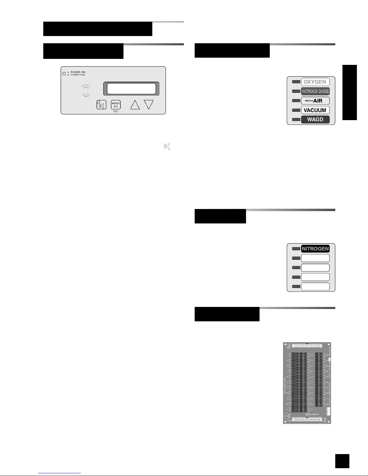
Features:
• User interface pushbuttons for alarm panel
TEST function, audible alarm MUTE
and set-up increase !and decrease ".
• Green alarm panel POWER ON indicator.
• Red flashing alarm system fault indicator.
• Red audible alarm mute indicator.
• Audible alarm
• General fault relay that activates on any
alarm panel fault condition.
• Auxiliary relay that activates when the
audible alarm is sounding.
• Alphanumeric two line by 20 character
display (Master/Combo Alarms only).
• Embedded web server with web pages to
view and set up alarm.
• 10Base-T Ethernet Jack.
• Ethernet LINK, TX and RX indicators.
• Heartbeat indicator.
• Event log.
(Master/Combo Alarms only)
Features:
• Monitors up to 64 normally
closed dry-contact switch
signals.
• Five gas service indicators
for normal (green) or abnormal (red)
conditions.
• Signal inputs can be programmed to any of
the gas service indicators.
• Adjustable brightness of LED indicators.
• Heartbeat indicator.
(Master/Combo Alarms only)
Features:
• Adds an additional five
gas service indicators to a
Multiplexer Module.
(Master/Combo Alarms only)
Features:
• Screw terminals for 32
dry-contact switch
signals.
• Terminals accept 14 to
22 AWG wires.
• Connector for optional
relay board.
Introduction
Breakout Board
LED Module
Multiplexer Module
Annunciator Module
Alarm Modular Components
66-847718-00 Rev. B00
Introduction
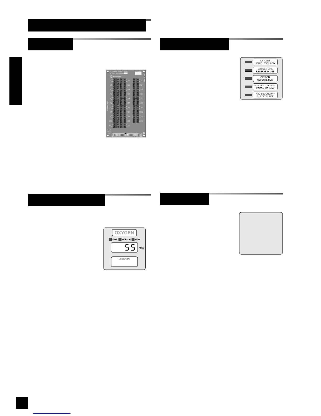
(Area/Combo Alarms only)
Features:
• Digital LED readout of
system pressure signal
transmitted from sensor
module.
• Adjustable brightness of
digital LED readout.
• Individual LED’s indicate when system
pressure/vacuum is HIGH (red), LOW
(red), or NORMAL (green).
• Programmable high and low alarm
thresholds.
• Adjustable audible alarm mute duration.
• Individual high and low alarm dry-contact
relay outputs.
• Can transmit pressure or vacuum signal to
another digital display module for remote
applications.
(Area Alarms only)
Features:
• Monitors up to five
normally closed dry-
contact switch signals.
• Separate indicators for each of five signals
for normal (green) or abnormal (red)
conditions.
• Available (optional) with separate dry-
contact relay outputs for each of five
signals.
• Adjustable brightness of LED indicators.
Features:
• Reserves a space in
alarm panel for future
expansion.
• Used to fill unused alarm
panel module locations.
Alarm Modular Components (Cont.)
Blank Module
Multi-Signal Module
Digital Display Module
(Master/Combo Alarms only)
Features:
• Screw terminals for 32
dry-contact relay
outputs. Dry contacts
are normally-closed
when alarm panel is
powered.
• Relay contact ratings
are 2 A @ 30 VDC/0.5 A
@ 125 VAC
.
• Terminals accept 14 to
22 AWG wires.
Relay Board

7
6-847718-00 Rev. B00
Address Resolution Protocol (ARP)
Protocol used by a device to learn the MAC
address of another device so it can send it an
Ethernet packet.
Area Alarm Panel
Alarm panel that monitors medical gas and
vacuum systems serving a specific area.
Auxiliary Fault Relay
Single-pole double-throw dry-contact relay
output located on annunciator module. Used
to activate a remote alarm or building
management system. The relay will activate
whenever ANY audible alarm on panel is in
progress. Pressing MUTE button on
annunciator module deactivates relay until
audible alarm is again reactivated.
Combo Alarm Panel
Alarm panel that combines features of a
master alarm panel and an area alarm panel.
Crossover Cable
Network cable that swaps transmit and receive
pairs so cable can be used to connect two
computers or devices without the use of a hub
or switch.
Domain Name Server (DNS)
A device that has a list of device names
matched to IP addresses. Browsers use this
resource to locate the IP address of a named
device. NetBIOS name service provides this
function on a local network.
Dry-Contact
Electrical contact isolated or unconnected from
any electrical source.
Dynamic Host Configuration Protocol
(DHCP)
A protocol used by a server to assign IP
addresses to devices and computers.
Definitions
Definition of Statements
Statements in this manual preceded by following
words are of special significance.
WARNING: Means there is a possibility
of injury or death to yourself or others.
CAUTION: Means there is a possibility
of damage to unit or other property.
SHOCK HAZARD: Means there is a
possibility of electric shock.
NOTE: Indicates points of particular interest
for more efficient and convenient operation.
ATTENTION: Means precautions for
handling electrostatic sensitive devices are
to be observed.
Introduction

86-847718-00 Rev. B00
Introduction
Electromagnetic Compatibility (EMC)
Verification that a product meets required
standards for emmisions of and immunity from
electromagnetic energy in its intended
environment.
Ethernet
A standard high-speed network medium
specified by IEEE standard 802.3.
Ethernet Hub
A device that connects many Ethernet devices
together. All devices on the hub receive
messages sent from all of the other connected
devices.
Ethernet Switch
A device that connects many Ethernet devices
together with optimization. Message
destinations are examined and passed only to
the correct device.
Firewall
A computer or computer software that prevents
unauthorized access to private data from
outside computer users.
Gateway
A computer or device that connects two
computer networks together (such as a private
network and the Internet).
General Fault Relay
Single-pole double-throw dry-contact relay
output located on annunciator module. Used to
activate remote alarm or building management
system. Relay will activate whenever ANY
audible alarm on panel is in progress. Unlike
Auxiliary Fault Relay, pressing MUTE button
on annunciator module WILL NOT deactivate
relay. General Fault Relay will deactivate only
after alarm condition is corrected and alarm
panel resumes normal status.
HyperText Transfer Protocol (HTTP)
Protocol used to manage the request and
transfer of web pages to a computer.
Internet Protocol (IP) Address
Unique number that identifies a device on a
network.
LED
Light Emitting Diode
Local Sensors
Pressure / vacuum sensors mounted inside
alarm panel back box. Sensor rough-in must
be piped to medical gas / vacuum pipelines.
Media Access Control (MAC) Address
A unique hardware address of a device on an
Ethernet.
Master Alarm Panel
Monitors medical gas and vacuum source
equipment and main pipelines.
NetBIOS Name Service
Local method of addressing a device by name.
This allows a web browser to reference a
device by name, such as TA2_12345, instead of
an IP address, such as 192.168.2.3.
Remote Sensors
Pressure / vacuum sensors mounted outside of
alarm panel back box. Sensor rough-ins may
be mounted separately or ganged together near
pressure / vacuum pipelines. Sensors must
then be wired to alarm panel.
Simple Mail Transfer Protocol (SMTP)
Protocol for sending email on a network.
Subnet Mask
A binary number used to separate the network
portion from the host portion of a network
address.
SMTP Client
Computer or device that uses SMTP to send
email by communicating with an SMTP server.
The TotalAlert 2 acts as an SMTP client.
SMTP Server
Computer or device that uses SMTP to receive
email from an SMTP client and then transfer it
across the internet.
Definitions (Cont.)

9
6-847718-00 Rev. B00
Transmission Control Protocol (TCP)
Protocol used to send data streams between
two devices. TCP guarantees reliable and in
order data from sender to receiver.
User Datagram Protocol (UDP)
Protocol used to send short messages between
computers. UDP does not guarantee reliable
transmission (packets may be lost, duplicated or
out of order), but is faster and more efficient
than TCP.
VFD
Vacuum Fluorescent Display
Definitions (Cont.)
Introduction

10 6-847718-00 Rev. B00
Alarm Configurations
Introduction
All TotalAlert 2 alarm panels are factory pre-
configured. Configuration of alarm panel varies
dependent upon customer’s requirements.
Three types of alarm panels are available.
• Master alarms (6-TA2M series) (Page 11)
• Area alarms (6-TA2A series) (Page 12)
• Combo alarms (6-TA2C series) (Page 14)
11
6-847718-00 Rev. B00
Model Number Scheme:
6-TA2M _ _ _
32 or 64
Designates number
of signals
R or blank
R = With Relays
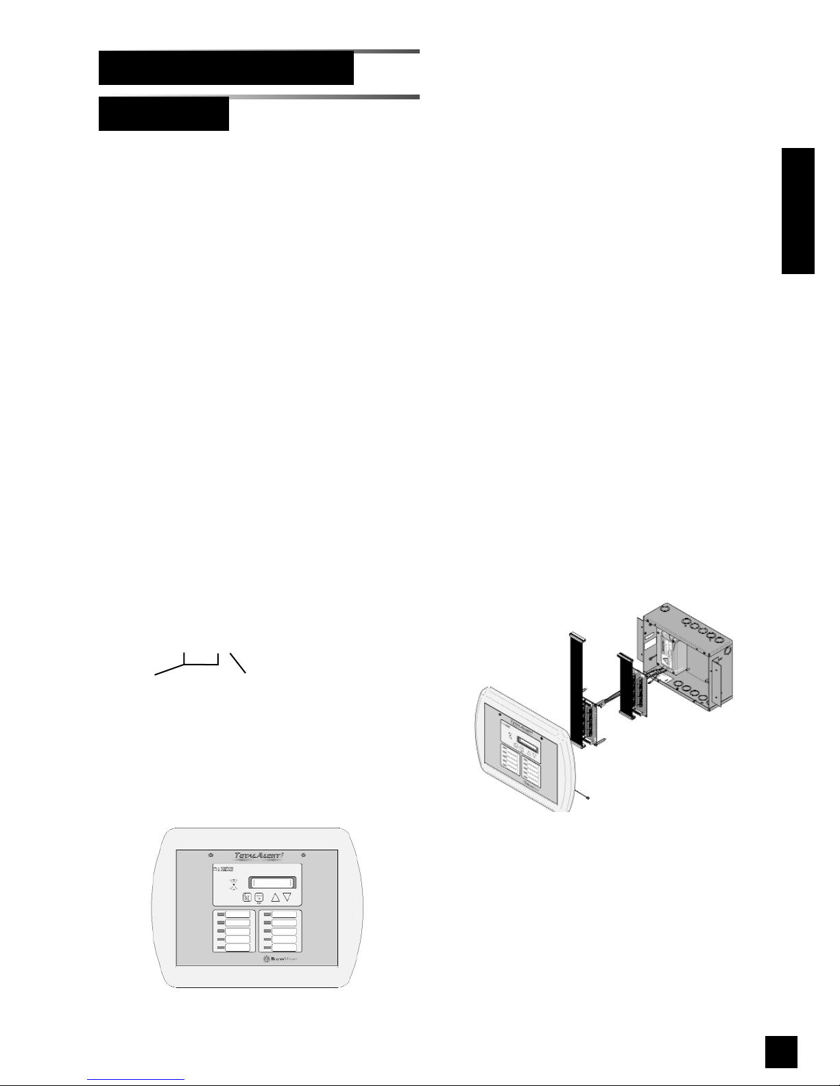
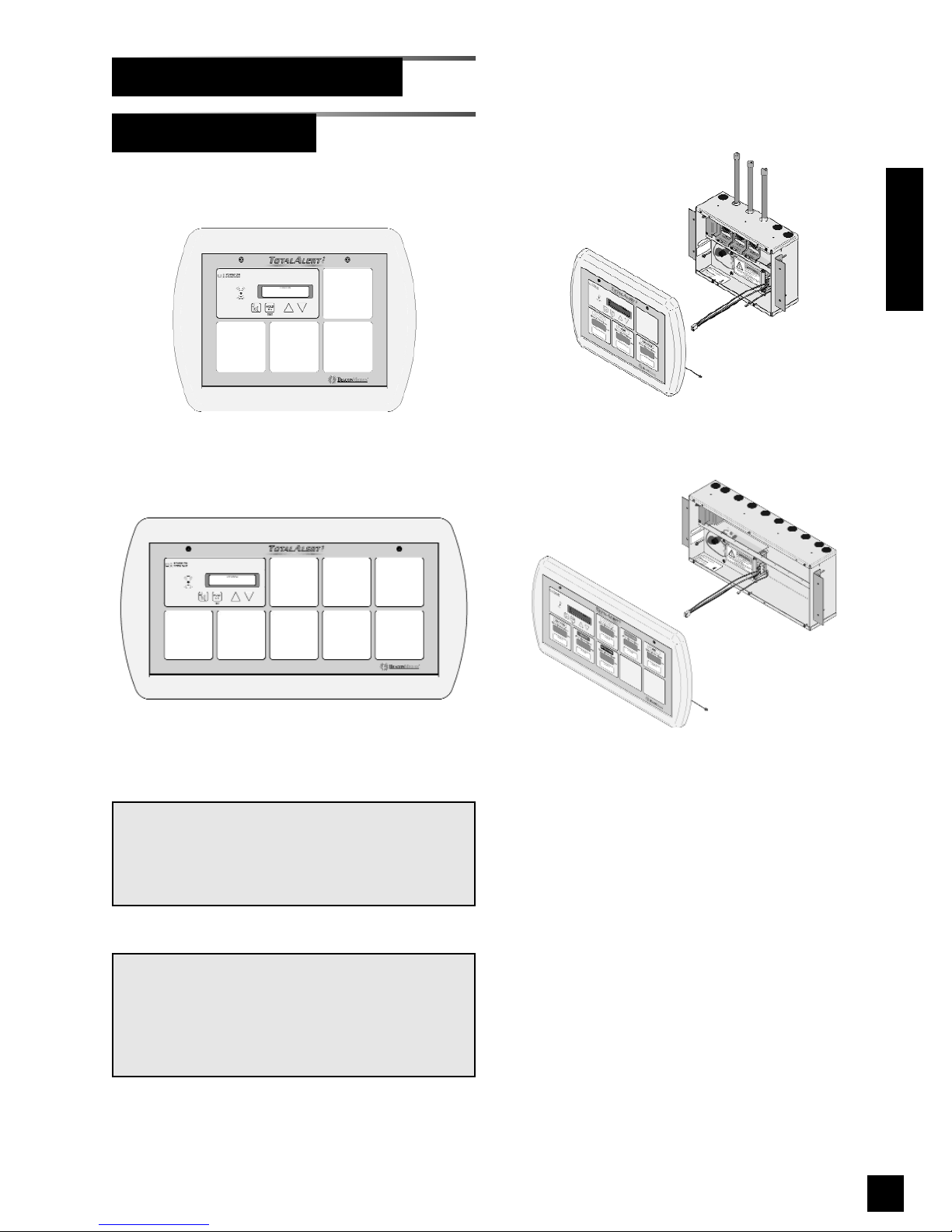
Master alarm panels include the following
modular components:
• Annunciator module with VFD
• One multiplexer module
• One LED module
• One or two breakout boards
• One or two relay boards (Optional)
Master alarm panels can monitor 32 or 64
switched inputs.
Inputs can be assigned to any one of 10
gas service indicators.
2 line by 20 character vacuum fluorescent
display shows signal names.
Optional dry contact relays are available
for all signals.
Master Alarms
Alarm Configurations (Cont.)
Example: P/N 6-TA2M32R
Introduction
Figure 4: Master Alarm
Figure 3: Master Alarm Panel
12 6-847718-00 Rev. B00
Introduction
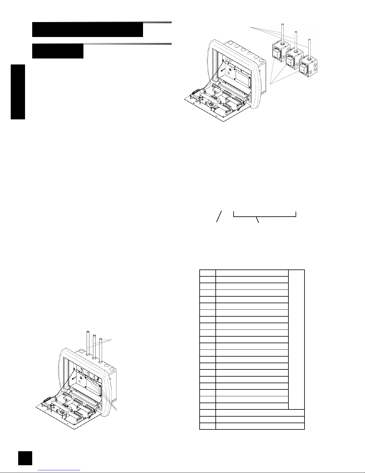
Sensor modules are
mounted inside alarm
panel box
Copper tubes connect to
pressure/vacuum
pipelines
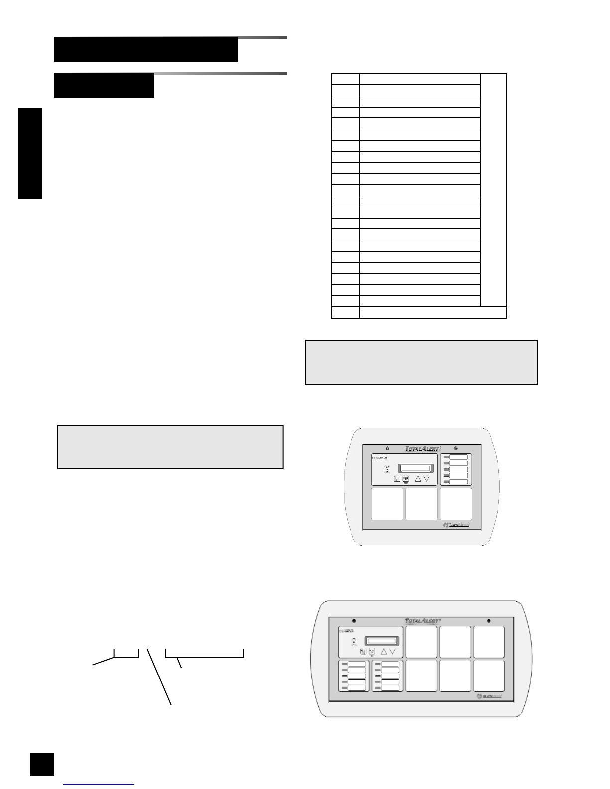
Area alarm panels include the following modular
components:
• Annunciator module
• 4 or 8 digital display, multi-signal or blank
modules
• Sensors for all digital display modules
(except 6-TA2AN series)
Area alarm panels may consist of any
combination of digital display modules, multi-
signal modules or blank modules.
If alarm panel is configured with digital display
modules, pressure/vacuum sensors will be
included for connection to pressure / vacuum
pipeline (except 6-TA2AN series).
Sensors may be located inside alarm panel
back box (local sensors) or outside alarm panel
back box (remote sensors).
Local sensors must be connected to pressure /
vacuum pipelines via copper tubing (Figure 5).
Remote sensor may be mounted near pressure
/ vacuum pipeline and then wired to alarm panel
(Figure 6).
Two alarm panel sizes support either 4 or 8
alarm modules.
Area Alarms
O
OXYGEN
D
OXYGEN - 100 PSI
X
NITROUS OXIDE
A
MEDICAL AIR
F
MEDICAL AIR - 100 PSI
5
AIR (ISO)
7
LABORATORY AIR
2
O2-CO2
4
O2-He
C
CARBON DIOXIDE
G
CARBON DIOXIDE - 100 PSI
1
CO2-O2
3
He-O2
H
HELIUM
V
VACUUM
6
VACUUM (ISO)
8
LABORATORY VAC
W
WAGD
N
NITROGEN
9
INSTRUMENT AIR
J
ARGON
DIGITAL DISPLAY MODULES
M
MULTI-SIGNAL MODULE
R
MULTI-SIGNAL MODULE W/ RELAYS
B
BLANK
Alarm Configurations (Cont.)
Model Number Scheme:
12345678
6-TA2A _ - _ _ _ _ _ _ _ _
L = Local Sensors
R = Remote Sensors
N = No Sensors
Position within alarm panel
(Figures 7 and 8)
Designates type of alarm
panel component from table
Figure 5: Local Sensors
Figure 6: Remote Sensors
Sensors have separate
mounting boxes for
mounting near
pressure/vacuum
pipeline and then must
be wired to alarm panel
Copper tubes connect to
pressure/vacuum pipelines
13
6-847718-00 Rev. B00
NOTE:
When an alarm panel is ordered with either local
or remote sensors, ALL sensors will either be
local or remote. Alarm panels with combination of
local and remote sensors are not available.
NOTE:
Alarm panel components in table on previous
page are listed in order of criticality. Unless other-
wise specified, most critical component will fill
position one, next less critical component will fill
position two, etc. etc.
234
1
123
45678
Area Alarms (Cont.)
Alarm Configurations (Cont.)
Introduction
Example: Model Number 6-TA2AR-OXAVWNBB
Example: Model Number 6-TA2AL-BOAV
Figure 10: Large Area Alarm
Figure 9: Small Area Alarm Panel
Figure 8: Large Area Alarm Front Panel
Figure 7: Small Area Alarm Front Panel
14 6-847718-00 Rev. B00
123
Figure 12: Large Combo Alarm Front Panel
123
456
Model Number Scheme:
123456
6-TA2C _ _ _ - _ _ _ _ _ _
Position within alarm panel
(Figures 11 and 12)
Designates type of alarm
panel component from table
Alarm Configurations (Cont.)
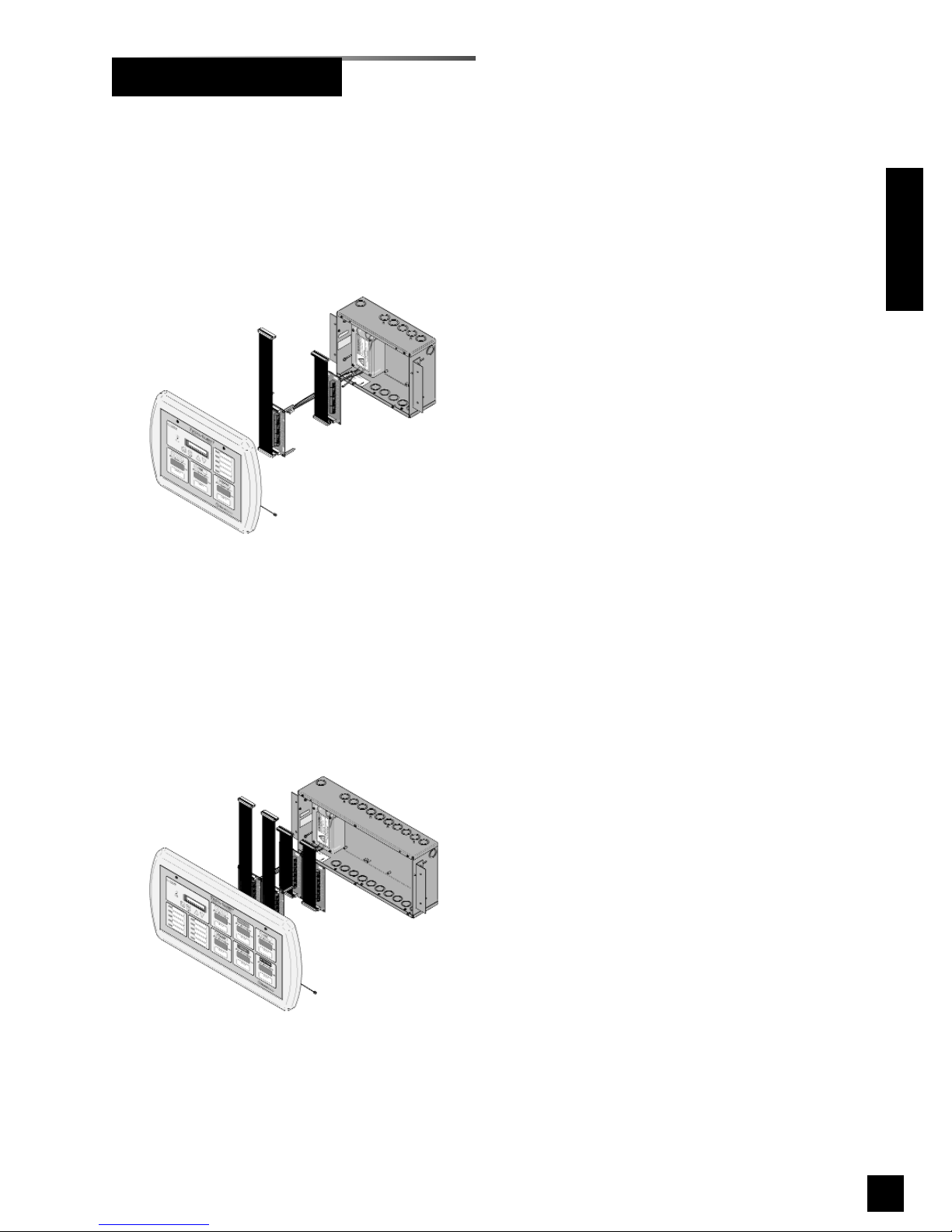
Combo Alarms
Combo alarms include the following modular
components:
• Annunciator module with VFD
• One multiplexer module
• One LED module (Large Combo Only).
• One or two breakout boards
• One or two relay boards (Optional)
• 3 or 6 digital display or blank modules
Combo alarms can monitor 32 or 64
switched inputs.
Inputs can be assigned to any one of 5
(small combo) or 10 (large combo) gas
service indicators.
Optional dry contact relays are available
for all signals.
Combo alarms can also monitor up to 3
(small combo) or 6 (large combo) digital
display modules.
NOTE:
Sensors on combo alarms are always remotely
mounted.
32 or 64
Designates number
of signals
R or blank
R = With Relays
O
OXYGEN
D
OXYGEN - 100 PSI
X
NITROUS OXIDE
A
MEDICAL AIR
F
MEDICAL AIR - 100 PSI
5
AIR (ISO)
7
LABORATORY AIR
2
O2-CO2
4
O2-He
C
CARBON DIOXIDE
G
CARBON DIOXIDE - 100 PSI
1
CO2-O2
3
He-O2
H
HELIUM
V
VACUUM
6
VACUUM (ISO)
8
LABORATORY VAC
W
WAGD
N
NITROGEN
9
INSTRUMENT AIR
J
ARGON
DIGITAL DISPLAY MODULES
B
BLANK
NOTE:
Multi-signal modules are not allowed in
combination alarms.
Introduction
Figure 11: Small Combo Alarm Front Panel
15
6-847718-00 Rev. B00
Example: Model Number 6-TA2C64-OXAVWN
Example: Model Number 6-TA2C32R-OAV
Combo Alarms (Cont.)
Introduction
Figure 14: Large Combo Alarm Panel
Figure 13: Small Combo Alarm Panel

16 6-847718-00 Rev. B00
This device complies with part 15 of the
FCC Rules. Operation is subject to the fol-
lowing two conditions: (1) This device may
not cause harmful interference, and (2) this
device must accept any interference
received, including interference that may
cause undesired operation.
This Class A digital apparatus complies
with Canadian ICES-003.
Cet appareil numérique de la classe A est
conforme à la norme NMB-003 du Canada.
Medical Electrical Equipment needs spe-
cial precautions regarding EMC and needs
to be installed and put into service accord-
ing to the EMC information provided in this
manual.
Portable and mobile RF communications
equipment can affect Medical Electrical
Equipment.
The use of accessories, transducers, and
cables other than those specified by the
manufacturer, may result in increased
emissions or decreased immunity of the
TotalAlert 2.
The TotalAlert 2 should not be used adja-
cent to, or stacked with, other equipment. If
adjacent or stacked use is necessary, the
TotalAlert 2 should be observed to verify
normal operation in the configuration in
which it will be used.
EN 60601-1-2
ICES-003
FCC
Electromagnetic Compatibility
Introduction

17
6-847718-00 Rev. B00
Electromagnetic Compatibility (Cont.)
Introduction
EN 60601-1-2 (Cont.)
Guidance and manufacturer's declaration - electromagnetic emissions
The TotalAlert 2 is intended for use in the electromagnetic environment specified below. The customer or the user of the TotalAlert 2
should assure that it is used in such an environment.
Emissions test Compliance Electromagnetic environment - guidance
RF emissions
CISPR 11 Group 1
The TotalAlert 2 uses RF energy only for its internal function. Therefore, its RF
emissions are very low and are not likely to cause any interference in nearby electronic
equipment.
RF emissions
CISPR 11 Class A The TotalAlert 2 is suitable for use in all establishments other than domestic and those
directly connected to the public low-voltage power supply network that supplies
buildings used for domestic purposes.
Harmonic emissions
IEC 61000-3-2 Class A
Voltage fluctuations/
Flicker emissions
IEC 61000-3-3
Complies
Guidance and manufacturer's declaration - electromagnetic immunity
The TotalAlert 2 is intended for use in the electromagnetic environment specified below. The customer or the user of the TotalAlert 2
should assure that it is used in such an environment.
Immunity test IEC 60601
test level Compliance level Electromagnetic environment - guidance
Electrostatic
Discharge (ESD)
IEC 61000-4-2
±6 kV contact
±8 kV air
±6 kV contact
±8 kV air
Floors should be wood, concrete or ceramic tile. If floors
are covered with synthetic material, the relative humidity
should be at least 30 %.
Electrical fast
transient/burst
IEC 61000-4-4
±2 kV for power supply
lines
±1 kV for input/output
lines
±2 kV for power supply
lines
±1 kV for input/output
lines
Mains power quality should be that of a typical
commercial or hospital environment.
Surge
IEC 61000-4-5
±1 kV differential mode
±2 kV common mode
±1 kV differential mode
±2 kV common mode
Mains power quality should be that of a typical
commercial or hospital environment.
Voltage dips, short
Interruptions and
voltage variations
on power supply
input lines
IEC 61000-4-11
<5 % UT
(>95 % dip in UT)
for 0,5 cycle
<40 % UT
(>60 % dip in UT)
for 5 cycles
<70 % UT
(>30 % dip in UT)
for 25 cycles
<5 % UT
(>95 % dip in UT)
for 5 sec
<5 % UT
(>95 % dip in UT)
for 0,5 cycle
<40 % UT
(>60 % dip in UT)
for 5 cycles
<70 % UT
(>30 % dip in UT)
for 25 cycles
<5 % UT
(>95 % dip in UT)
for 5 sec
Mains power quality should be that of a typical
commercial or hospital environment. If the user of the
TotalAlert 2 requires continued operation during power
mains interruptions, it is recommended that the
TotalAlert 2 be powered from an uninterruptible power
supply or battery.
Power frequency
(50/60 Hz) magnet-
ic field
IEC 61000-4-8
3 A/m 3 A/m Power frequency magnetic fields should be at levels
characteristic of a typical location in a typical commercial
or hospital environment.
NOTE UTis the a.c. mains voltage prior to application of the test level.

18 6-847718-00 Rev. B00
Introduction
Electromagnetic Compatibility (Cont.)
EN 60601-1-2 (Cont.)
Guidance and manufacturer's declaration - electromagnetic immunity
The TotalAlert 2 is intended for use in the electromagnetic environment specified below. The customer or the user of the TotalAlert 2
should assure that it is used in such an environment.
Immunity test IEC 60601
test level Compliance level Electromagnetic environment - guidance
Conducted RF
IEC 61000-4-6
Radiated RF
IEC 61000-4-3
3 Vrms
150 kHz to 80 MHz
3 V/m
80 MHz to 2,5 GHz
3 Vrms
3 V/m
Portable and mobile RF communications equipment should be
used no closer to any part of the TotalAlert 2, including cables,
than the recommended separation distance calculated from the
equation applicable to the frequency of the transmitter.
Recommended separation distance
d= 1,2√P
d= 1,2√P80 MHz to 800 MHz
d= 2,3√P800 MHz to 2,5 GHz
where Pis the maximum output power rating of the transmitter in
watts (W) according to the transmitter manufacturer and dis the
recommended separation distance in metres (m).
Field strengths from fixed RF transmitters, as determined by an
electromagnetic site survey, ashould be less than the compliance
level in each frequency range. b
Interference may occur in the vicinity of equipment marked with
the following symbol:
NOTE 1 At 80 MHz and 800 MHz, the higher frequency range applies.
NOTE 2 These guidelines may not apply in all situations. Electromagnetic propagation is affected by absorption and reflection from
structures, objects and people.
aField strengths from fixed transmitters, such as base stations for radio (cellular/cordless) telephones and land mobile radios,
amateur radio, AM and FM radio broadcast and TV broadcast cannot be predicted theoretically with accuracy. To assess the
electromagnetic environment due to fixed RF transmitters, and electromagnetic site survey should be considered. If the
measured field strength in the location in which the TotalAlert 2 is used exceeds the applicable RF compliance level above, the
TotalAlert 2 should be observed to verify normal operation. If abnormal performance is observed, additional measures may be
necessary, such as reorienting or relocating the TotalAlert 2.
bOver the frequency range 150 kHz to 80 MHz, field strengths should be less than 3 V/m.
Table of contents
Other BeaconMedaes Security System manuals


