17
Medical Gas Supply System
4109992485.00
Pressuredropleaktestvalidationnotes:
• The Manifold Changeover System uses medical
regulatorsapprovedtoBSENISO10524-2standard,
as required by ISO and HTM medical pipeline
standards. These standards have a maximum
allowableleakageacrosstheregulatorseat(internal)
andtoatmosphere(external)asfollows:
1ststageregulator,Internal 0.1ml/min
1ststageregulator,external 0.2ml/min
2ndstageregulator,Internal 0.2ml/min
2ndstageregulator,external 0.2ml/min
• Therefore, the maximum pressure increase or
decrease witnessed at the line pressure will be
based on 2 regulators, 0.4 ml/min. The maximum
pressure drop witnessed at the cylinder pressure
will be based on the internal and external leakage
fromthe1st and 2ndstageregulatoronthatbank,0.7
ml/min.
• Pressuredroptestsaremorecommonlyusedonsite,
asleakscanbediculttomeasure.Theequivalent
watercapacityvolumeundertestisusedtocalculate
thepressuredropfromanallowableleakagerate.
• Fromusingthemanifoldwatercapacitytheallowable
pressuredroporincreasebasedonaleakageof0.4
ml/mincanbecalculatedas0.0016bar/min,or0.096
bar/hrwitnessedatthelinepressure.Thepressure
dropwitnessedatthecylinderpressurefroma0.7
ml/min leakage would be as follows depending on
thenumberofcylinderconnections.
No.Cyl. 12345
Bar/Hr 1.78 1.09 0.78 0.61 0.5
No.Cyl. 67 8 9 10
Bar/Hr 0.42 0.37 0.33 0.29 0.26
• Althoughthemedicalregulatorallowableleakageis
onlysmall,theeectscanbewitnessedwithinafew
hours due to the manifold having a small volume.
To put into perspective how small 0.4 ml/min is, if
appliedtooneJ-sizecylinderitwouldtakenearly12
weeksforittodropby1bar.
2.6.8 Monitorthepressuredropandassessasperthe
abovenotes.Lengthoftimeforthetestwilldependon
theaccuracyofthegaugesusedtobeabletodetectthe
pressuredrop.
2.6.9 Opentestpointisolationvalve(gure1,item15)
andrelievethepressurefromwithinthemanifold,then
closetestpointisolationvalve.
2.6.10 TheinstallationmustnowbepurgedasperHTM
02-01forUKinstallations,orasperrelevantstandardsif
installedoutsidetheUK.
2.6 Installation Check.
2.6.1 Ensure that all tailpipes are connected to the
cylinders and manifolds on both sides and that the
restraintchainsaresecurearoundthecylinders.
2.6.2 Isolate the device from the pipeline using the
mainisolationvalve(showningure15,item3).
2.6.3 Ensure that both bank isolation valves (Figure
15,item1and2)arefullyopen.
2.6.4 Ensurethe test point isolation valve(gure 15,
item4)isclosed.
2.6.5 Use 1 cylinder per bank, slowly pressurise the
manifold (see section 4.10 - Cylinder operation). Both
cylinder gauges (gure 1, item 23) should indicate full
cylinderpressure.Thelinepressuregauge(gure1,item
18)shouldreadtypicallyaspertable6,Section4,adjust
asnecessary(seesection4.5).
CAUTION!Ifusedasabackupmanifolditwould
berecommendedtosetthelinepressureatleast0.2bar
below the main supply source pressure at full design
ow,toensurethemanifolddoesnotsupplythepipeline
duringnormalprimarysourceoperation.
2.6.6 Check for leaks, typically by listening for gas
escapingorleakdetectionuidonjoints.
2.6.7 Nowensureallbank cylindervalvesare closed
readyforpressuredropleaktest.
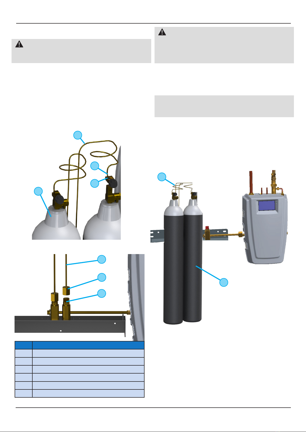
Figure 15 - Leak Test Valve Conguration.
3
4
1
2
No. Description
1LineIsolationValve
2IntermediateIsolationValve(ThreeWay)
3LockableIsolationValve
4TestPointIsolationValve