Beam Commertial User manual

BEAM Commercial
Operation Manual
This appliance is suitable for commenrcial use, for example in hotels, schools,
hospitals, factories, shops, offices, and rental businesses, etc.
CAUTION: This appliance is not suitable for picking up hazardous dust.
Read these instructions manual before using this appliance.

2
TABLE OF CONTENTS
IMPORTANT SAFEGUARDS 3
1. General safety information 4
1.1. Purpose of this manual 4
1.2. Composition of the manual and consultation details 4
1.3. General safety precautions 4
1.4. Identication of the manufacturer 5
1.5. Technical documentation supplied with the BEAM Commercial central vacuum unit 6
1.6. Standard equipment supplied with the BEAM Commercial central vacuum unit 6
1.7. Correct and improper uses 6
2. Technical characteristics 6
2.1. Description of the BEAM Commercial central vacuum unit 6
2.2. Standard models and approximate dimensions 7
2.3. Technical data and characteristics 8
2.4. Frame 9
2.5. Dust container 9
2.6. Central section 9
2.7. Top section 9
2.8. Safety and hazard stickers 10
3. Movement and unpacking 10
4. Installation 11
4.1. Choice of installation position for the main central vacuum unit 11
4.2. Installation of the BEAM Commercial central vacuum unit 11
4.3. Electrical connections 11
5. Use and operation 12
5.1. Switching on rst time 12
5.2. Operation instructions 13
5.3. Final system test 13
5.4. Operation of the inverter on the control panel 13
5.5. Operation of the self-cleaning system 14
6. Maintenance 14
6.1. Routine maintenance 14
6.2. Replacement of dust collection bag 15
6.3. Replacement of the lter cartridge (lter) 15
6.4. Cleaning of the lter cartridge (lter) 16
6.5. Non-routine maintenance 16
7. Problems, causes and remedies 17
8. End of service and decommissioning 18
9. Information to be kept 18

3
IMPORTANT SAFEGUARDS
Read this manual carefully before starting operations of movement, unpacking, installation, use,
maintenance and decommissioning of the BEAM Commercial central vacuum unit.
SAVE THESE INSTRUCTIONS
WARNING
To reduce the risk of re, electric shock or injury:
• Vacuum units are for commercial use.
• Do not use the machine for inappropriate purposes.
• Do not suck up glowing embers, cigarette ends still lit, inammable products or materials that
could cause ames in the dust collection container, materials with a high risk of explosions
or materials that individually are inert but that when mixed together may cause dangerous
chemical reactions.
• It is prohibited to use vacuum units for unintended purposes in industrial facilities in the
presence of values of temperatures, pressure and humidity in excess of those of normal
workplaces.
• Do not suck up liquids, ashes in replaces, large quantities of our, printer toner, building site
dust, ne powder, cement or plaster, or hazardous dust.
• Do not suck up plaster, cement or rubble.
• Always disconnect the power supply at the electrical panel: during installation; if maintenance or
repair operations are necessary; if the system is not to be used for a long period.
• Do not under any circumstances whatsoever work on the unit while it is operating.
• Wear protective gloves and a face mask for all maintenance work (emptying of dust container,
cleaning or replacement of lter).
• Use only original spare parts.
• Do not use the vacuum unit without the lter.
• After all maintenance operations ensure that the lter has been replaced and correctly
tightened.
• Do not obstruct air inlets or outlets.
• Keep ngers and hands away from nozzles of accessories and openings of the vacuum unit,
and never direct the suction mouthpiece toward persons or animals.
• This system is designed to be installed by adequately trained and instructed personnel. Ask the
installer carrying out the nal system test to certify that the system has been correctly installed.
• In case of re, do not attempt to extinguish it with water. Failure to observe this instruction may
expose the operator to the risk of electric shock.

4
1. GENERAL SAFETY INFORMATION
1.1. Purpose of this manual
This installation, use and maintenance manual are an integral and essential part of the BEAM
Commercial Central Vacuum unit.
Its purpose is to provide all necessary information to allow the installer to install the system in full
compliance with the manufacturer’s specications, the user to operate the system in the safest
and most independent way, and maintenance technicians carrying out programmed maintenance
operations to ensure the correct operation of machinery and the system as a whole.
The manufacturer declines all liability for damage deriving from failure to observe the instructions
given in this manual. In case of doubts on the correct interpretation of instructions, contact your local
distributor/dealer to receive the necessary explanations.
1.2. Composition of the manual and consultation details
This installation, use and maintenance manual are composed of chapters divided into sections,
identied by a progressive numbering system at the start of each different topic. The table of contents
lists the chapters and sections, allowing the desired topic to be easily found.
The descriptions and illustrations provided in this manual are not binding. BEAM Electrolux reserves
the right to make any modications it deems necessary at any moment, without any obligation for
prior notication.
1.3. General safety precautions
The purpose of this information is to make persons interacting with the system aware of all possible
conditions of danger, and thereby to avoid injuries either to themselves or to others.
Design for safety
During the design and construction phase, the manufacturer dedicated particular attention to aspects
that may cause risks for the safety or health of persons using the system.
In addition to complying with applicable laws, the manufacturer followed all rules for Good
Manufacturing Practices.
Nevertheless, some parts of the system could cause risks that are not immediately evident. It is
therefore advisable to take particular care during use of the system and during routine maintenance
operations.
Safety during use
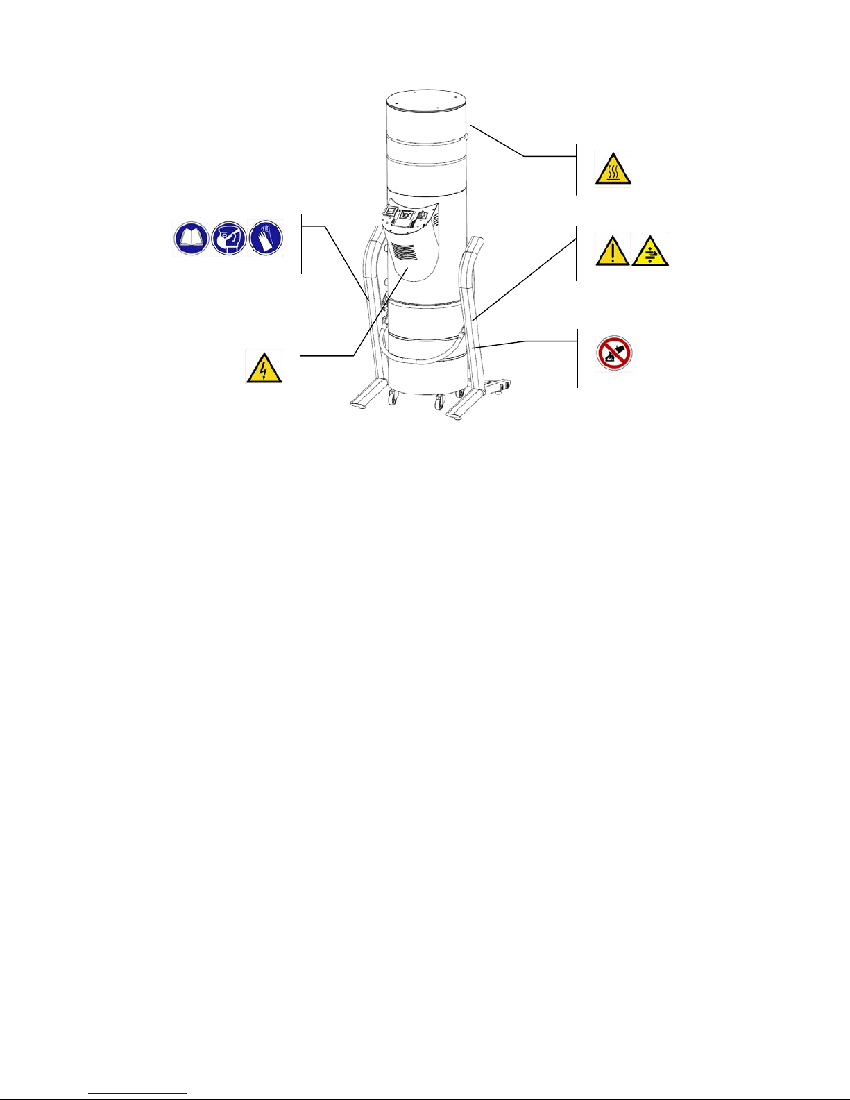
Before starting to use the system in any way whatsoever, the instructions given in this manual
supplied must be read carefully and completely, together with the indications provided directly on the
system with safety warning symbols.
Do not tamper with, bypass or remove the safety devices installed on the system.
Failure to observe these instructions may cause risks for the safety or health of persons.
Safety during maintenance
Personnel carrying out any kind of routine maintenance on the system during its entire lifespan must
possess specic technical skills, special capacities and acquired experience recognized in the sector
in question.
The absence of these requisites may cause risks for the safety or health of persons.

5
Figure 1.
During normal use or during any kind of operations on the system, the safety distances around it must be
maintained in order to avoid causing risks for the safety or health of persons.
For some operations the help of one or more assistants may be necessary.
1.4. Identication of the manufacturer
This BEAM Commercial central vacuum unit was designed and produced by BEAM Electrolux.
For all requests regarding installation, use, maintenance or the supply of spare parts, customers are to
contact the dealer or the distributor, the identication data for the unit can be found on the rating plate
(Figure 1).
The rating plate is located on the right-hand side of the vacuum unit.
For all requests for technical assistance, in addition to details of the problem encountered, customers are
asked to inform your local distributor/dealer of all system information given on the rating plate, as follows:
• model number
• serial number
For all requests regarding installation, use, maintenance or the supply of spare parts, contact your local
distributor/dealer, the identication data for the unit can be found on the rating plates.

6
1.5. Technical documentation supplied
• Operation Manual for BEAM Commercial central vacuum units
1.6. Standard equipment supplied
The following are supplied as standard accessories:
• 2 ttings with xing clamps for connecting the vacuum unit to the system
• 1 dust collection bag
1.7. Correct and improper uses
BEAM Commercial central vacuum units are designed and constructed solely to suck up dust of a
domestic type into a central unit inside civil buildings.
The BEAM Commercial system must be used to suck up only dust and objects of small dimensions.
For specic needs contact your local distributor/dealer. The manufacturer declines all and any liability
for damage to the system or to other things and/or injuries to persons caused by improper use of the
system.
ATTENTION: Uses other than those indicated are not permitted. No modications or adaptations
of the vacuum unit are permitted. Any use whatsoever other than the use for which the product has
been designed represents improper use that may damage the vacuum unit and constitute a serious
hazard for the user.
2. TECHNICAL CHARACTERISTICS
2.1. Description of the BEAM Commercial central vacuum unit
BEAM Commercial central vacuum units are designed and manufactured for the suction of dust both
in residential buildings and in service sector premises, such as hotels, cinemas, theatres, games
arcades, conference halls, offices, factories, etc.
BEAM Commercial central vacuum units use a suction turbine with an electric motor that generates
suction pressure when switched on. The rotation speed of the suction turbine is controlled by an
inverter. Depending on the suction pressure setting, the inverter controls the rotation frequency
according to the suction pressure detected by a pressure transducer.
The air sucked in is channelled into the central section, where dust particles fall into a collection
container. Finer particles are drawn towards the upper part of the separator, where they are trapped
by the lter cartridge. The ltered air is then expelled towards the exterior through the outlet ducts of
the turbine.

7
Characteristics BC126M BC126A BC238M BC238A
Number of operators 1 1 2 2
Work area (m²) up to 1500 up to 1500 up to 3000 up to 3000
Self-cleaning function no yes no yes
Technical data – Dimensions
Container capacity (L) 90 90 90 90
Diameter (cm) 46 46 46 46
Filter surface (m²) 2 2 2 2
Inlet/outlet diameter (mm) 63 63 63 63
Height (cm) 177 177 177 177
Width (cm) 70 70 70 70
Depth (cm) 85 85 85 85
Weight (kg) 104 112 104 112
2.2. Standard models and approximate dimensions
Figure 2.

8
2.3. Technical data and characteristics
Electrical protection class – Class 1 – Device with fundamental electrical insulation. Must be
connected to the grounding circuit of the main electrical system.
IP protection rating – IP20 (Devices protected against solid bodies greater than 12 mm in diameter
and not protected against the penetration of water).
A 0.3 A Class B safety cut-out breaker must be installed before the electrical panel.
Figure 3 gives a transparent view of the vacuum unit, allowing the main components to be seen.
Technical performance data BC126M BC126A BC238M BC238A
Maximum airow (m3/h) 350 350 460 460
Airow operating at 160 mBar (m3/h ) 180 180 340 340
Operating suction pressure (mBar) 160 160 160 160
Noise emission (dBA) 63 63 68 68
Electrical technical data
Motor power (kW) 2.6 2.6 3.8 3.8
Power supply voltage (V) 230 230 400 400
Power supply frequency (Hz) 50/60 50/60 50/60 50/60
Power absorbed (A) 6.7 6.7 9.7 9.7
Inverter yes yes yes yes
Maximum frequency (Hz) 70 70 86 86
Protection rating IP20 IP20 IP20 IP20
Electrical insulation Class 1 Class 1 Class 1 Class 1
Figure 3.
Turbine
Compressor
Main switch
Self-
cleaning
timer
Inverter
Frame
Dust
container
Top section
Dust
container
handle
Self-
cleaning
electronics
board
Cartridge
filter
Low-pressure pipe
for dust container
bag retention
Central
section
Stand

9
2.4. Stand
The frame is the support structure of the BEAM Commercial vacuum unit. Its adjustable support feet
allow the vacuum unit to be levelled even on irregular surfaces.
2.5. Dust container
The dust container has a collection capacity of 90 liters. The container has a dust collection bag for
the disposal of dust. The level of dust in the dust container must be checked approximately every two
months, depending on the conditions of use.
The handle is used to open the dust container, also making the cartridge lter accessible.
The dust container also has a low-pressure pipe that warrants the retention of the dust collection bag.
2.6. Central section
The central section contains the main control components of the BEAM Commercial central vacuum
unit, as follows:
• Electrical control panel
- Inverter
- Main switch
- Self-cleaning timer (BC126A and BC238A)
- Electronics board for control of the lter self-cleaning function (BC126A and BC238A)
• Cartridge lter
• Pressure transducer for regulation of the operating suction pressure
• Compressor for lter self-cleaning function (BC126A and BC238A)
• Compressed air tank for lter self-cleaning function (BC126A and BC238A)
• Solenoid valve for lter self-cleaning function (BC126A and BC238A)
• Suction inlet pipe Ø63 mm
2.7. Top section
The top section contains the turbine, and is soundproofed to make operation of the BEAM
Commercial central vacuum unit as silent as possible. The top section is tted with a Ø63 mm air
exhaust pipe.
2.8. Safety and hazard stickers
Figure 4 on the following page shows the points where stickers with recommendations, hazard
warnings and prohibitions are applied, helping to make the BEAM Commercial central vacuum unit
safer to use.

10
3. MOVEMENT AND UNPACKING
The BEAM Commercial central vacuum unit is shipped xed to a europallet inside a cardboard carton
to protect it during transport and delivery.
It is advisable not to remove the packaging until the moment of installation, to avoid possible damage.
Upon delivery check that the shipment is correct without any damages.
In case of any missing parts and/or damages proceed as follows:
• Note the type of damage on the transport document (transporter’s copy);
• Send the transporter a registered letter requesting compensation for the damage within two days;
• Contact the distributor for any necessary replacement parts.
ATTENTION:
• Suitable lifting equipment must be used when moving the vacuum unit and particular care must
be taken to correctly balance loads.
• The support surface must not have a slope of more than 8%, to avoid the risk of overturning due
to loss of stability.
• During movement operations use appropriate items of personal protection equipment.
• Failure to use appropriate items of personal protection equipment during movement and
unpacking may expose the operator to the risk of crushing of the feet due to loss of stability.
• Wear safety gloves for a safe grip during movement.
CAUTION:
• Keep the vacuum unit right-side up at all times.
• Do not use box cutters to remove packaging materials.
• The manufacturer declines all and any liability for damage caused by the incorrect unpacking of
materials.
Figure 4.

11
4. INSTALLATION
This system is designed to be installed by adequately trained and instructed personnel. The entire
system must be installed by qualied personnel in full compliance with standards of workmanship and
with applicable standards and regulations.
ATTENTION:
During installation operations use appropriate items of personal protection equipment.
4.1. Choice of installation position for the main vacuum unit
The choice of installation position must be based on these criteria:
• The BEAM Commercial vacuum unit must be installed indoors in well-ventilated rooms, preferably
in a service room on the lowest oor of the building, like a garage or technical utilities room, or in
external locations, provided that the vacuum unit is always protected against bad weather.
• The selected position must have a clear and well-lit space around the main vacuum unit, so as to
facilitate maintenance and repair operations.
• The main vacuum unit must not be installed in rooms where:
- there is a source of heat in the immediate vicinity
- ambient temperature can reach values lower than 5°C and above 35°C
- humidity is very high or ooding may occur
- ammable or explosive products are present
• The installation position must permit the tting of air exhaust pipes no longer than ve metres with
Ø63 mm pipes. After this distance, Ø80 mm pipes must be used.
4.2. Installation of the BEAM Commercial central vacuum unit
This unit has been designed for easy and convenient installation.
The vacuum unit must be positioned respecting the clearance distances indicated in Figure 5. There
must be a space of 5 cm on each side of the vacuum unit, and a space of 25 cm to the rear.
In these installation conditions, the suction inlet is 70 cm above oor level and 25 cm from the rear
wall. The air exhaust outlet is 150 cm above the oor and also 25 cm from the rear wall.
The BEAM Commercial vacuum unit must now be connected to the suction pipes of the system and to
the air exhaust pipe, using the rubber hoses with metallic xing clamps provided.
IMPORTANT:
• For the air exhaust pipe, the rst ve metres must consist in Ø63 mm pipes. After the rst ve
metres, pipe diameter must be increased to Ø80 mm.
4.3. Electrical connections
Complete installation without connecting the vacuum unit to the mains electrical system.
After connecting the air pipes, the main electrical power supply must be connected to the machine,
using a single-phase 230 V supply for models BC126A and BC126M and a triple-phase 400 V supply
for models BC238A and BC238M.
To complete installation, connect the low-volt wires.

12
The power supply cord and the low-volt wires are connected to the vacuum unit from the rear (Figure
5).
Electrical protection class – Class 1 – Device with fundamental electrical insulation.
Must be connected to the grounding circuit of the main electrical system.
A 0.3 A Class B safety cut-out breaker must be installed before the electrical panel.
5. USE AND OPERATION
The completed system must be started for the rst time only by an authorized technician.
5.1. Switching on rst time
After the safety and correct operation of the system have been checked, it is essential to ensure that
all persons who will be involved in operation of the system are suitably trained and made aware of
all the information provided in this manual. In particular, they must be informed of the risks involved
in operation of the system and of the precautions to be taken to reduce risks during operation to a
minimum.
5.2. Operation instructions
Switching on
• move the main switch on the control panel to position 1 (Figure 3);
• insert the exible hose into an inlet valve, and switch on the system on the hose handle.
Switching off
• switch the system off on the hose handle, and remove the exible hose from the inlet valve.
Exit for power supply
cable and consent cable
for suction points
Figure 5.
Power supply cord and low
volt wire connections

13
NOTE: It is advisable to keep the power supply to the vacuum unit turned on, allowing it to be
restarted for subsequent uses. If instead the system will not be used for a long period of time, it is
recommended to move the main switch on the control panel to the 0 position.
5.3. Final system test
After the industrial vacuum unit has been started for the rst time, the system can be checked. It must
have no leaks.
To check that the system has no leaks, rst inspect the suction points (with the turbine operating) and
check that they are airtight with the cover closed.
Finally check the airtightness of the vacuum pipes, using a VACUUM METER to measure the low-
pressure value at one suction point on every operation line of the system, and comparing the value
obtained with the values measured on the vacuum unit when this is disconnected from the system.
5.4. Operation of the inverter on the control panel
On BEAM Commercial central vacuum units, the inverter controls operation of the suction turbine.
A transducer that measures operating suction pressure is connected to the inverter. Using the signals
received, the inverter maintains the pre-set operating parameters constant, increasing or reducing the
rotation frequency of the turbine as the conditions of use vary or according to the number of suction
hoses connected.
For BC238M and BC238A vacuum unit models, the operating suction pressure can be pre-set from a
maximum of 250 mBar H2O to a minimum of 130 mBar H2O as follows:
Double-click to move to the REF menu.
Use the central button to enter the REF menu.
Scroll through the numerical values with the left or right buttons.
Increase or decrease the values with the up/down buttons.
Conrm the value set with the central button.
Press the up button twice to return to the main display.
All operating parameters are optimized by the manufacturer, and the suction pressure is pre-set to
-160 mBar H2O.
or

14
5.5. Operation of the self-cleaning system
Models BC126A and BC238A have a self-cleaning system for the lter that can operate at intervals
programmable according to requirements, limiting maintenance to the replacement of the collection
bag.
A timer controls for frequency of daily cleaning of the lter (Figure 3).
Operation of the device is triggered by a compressor that feeds a pressure tank with a capacity of
three liters of air up to a predetermined pressure of 5 bar. At this point an instantaneous air jet is
channelled into the lter through a nozzle. This allows the lter to be kept clean for a longer period.
The lter cleaning parameters pre-set by the manufacturer are as follows:
• 1 daily lter cleaning cycle
• Duration of cleaning cycle 3 minutes
• Start of cleaning cycle at 5 AM
The start time, duration and number of lter cleaning cycles can be varied by changing the timer
settings. The date and time of the timer can also be regulated.
IMPORTANT: During the self-cleaning cycle do not open the dust collector container, and after the
end of the cycle wait at least one minute before opening it
Make annual inspections on the lter to ensure that it is undamaged and to check if it needs
washing (if washed, the lter must be dry before being replaced).
6. MAINTENANCE
6.1. Routine maintenance
Accurate maintenance extends the operational life of the system and ensures constant performance
over time, helping to prevent problems due to unexpected system stop.
ATTENTION: Before proceeding with maintenance operations of any kind whatsoever, unplug the
system from the electrical power supply. Failure to comply with this instruction may expose the
operator to the risk of electric shock.
The intervals between periodic maintenance operations may vary according to the type of use.
Periodic operations Normal frequency
Check lling level of the dust collector bag in the dust container Every month
Check lter cartridge for possible clogging Every month
Cleaning of lter cartridge (models without self-cleaning) Max. every 2 months
Cleaning of lter cartridge (models with self-cleaning) Every year
Replacement of lter cartridge 2 years

15
6.2. Replacement of dust collection bag
The dust collection bag inside the separator must be replaced at periodic intervals, as indicated in the
“Periodic operations” chart on the previous page.
CAUTION:
• Before proceeding with replacement operations, a protective mask and gloves must be used.
• Use only original spare bags by BEAM Electrolux.
• Failure to use these items of personal protection equipment may expose the operator to the risk of
inhalation of dust that is harmful to health, or of the contact of allergenic substances with the skin.
• Before proceeding with replacement operations, the power supply cable must be unplugged.
Failure to comply with this instruction may expose the operator to the risk of accidental system
starting.
• While the dust container is being hooked up, there is the risk of cutting injuries to the ngers.
• After completing any maintenance operation, remember that the vacuum unit must not be
restarted before the lter cartridge is mounted correctly.
The replacement procedure for the dust collection bag is as
follows:
1. Unhook the lower module of the separator by raising the
handle.
2. Extract the lower module of the separator by allowing it
to slide on its wheels with the assistance of the handle
provided.
3. Extract the dust collection bag and replace it with a new
one.
4. Fold the edges of the bag towards the exterior.
5. Hook up the dust container again to the separator. If
it is necessary to move the dust container away from
the separator to empty the dust collection bag, the
depression pipe keeping the bag in the correct position
must be disconnected.
6.3. Replacement of the lter cartridge (lter)
The lter cartridge must be checked and if necessary replaced when a progressive reduction of the
suction power of the system is noted. Replacement is always necessary after two years of use.
CAUTION:
• Before proceeding with replacement operations, a protective mask and gloves must be put on.
• Use only original spare bags by BEAM Electrolux.
• Failure to use these items of personal protection equipment may expose the operator to the risk of
inhalation of dust that is harmful to health, or of the contact of allergenic substances with the skin.
• Before proceeding with replacement operations, the power supply cable must be disconnected.
Failure to comply with this instruction may expose the operator to the risk of accidental system
starting.
• While the dust container is being hooked up, there is the risk of cutting injuries to the ngers.
• After completing any kind of maintenance operation, remember the suction unit must not be
restarted without rst having inserted the lter cartridge inside the separator.

16
The replacement procedure for the lter cartridge is as
follows:
1. Unhook the lower module of the separator by
raising the handle.
2. Extract the lower module of the separator by
allowing it to slide on its wheels with the assistance
of the handle provided.
3. Unscrew the black knob holding the lter cartridge
in position.
4. Extract the lter cartridge.
5. Replace the lter cartridge and repeat the above
operations in the reverse order.
6.4. Cleaning of the lter cartridge (lter)
The lter cartridge should be cleaned/changed at the scheduled intervals (see section 6.1).
CAUTION:
• Before proceeding with replacement operations, a protective mask and gloves must be put on.
• Use only original spare bags by BEAM Electrolux.
• Failure to use these items of personal protection equipment may expose the operator to the risk of
inhalation of dust that is harmful to health, or of the contact of allergenic substances with the skin.
• Before proceeding with replacement operations, the power supply cable must be disconnected.
Failure to comply with this instruction may expose the operator to the risk of accidental system
starting.
• While the dust container is being hooked up, there is the risk of cutting injuries to the ngers.
Dismount the lter cartridge to be cleaned/changed (see details of this operation in previous section),
and if a replacement cartridge is available, use it to replace the cartridge to be cleaned. Clean the
dirty cartridge with the vacuum unit, using the brush accessory for corners, taking care to avoid
damage to the lter fabric. As an alternative, the lter can be washed with water.
If the lter fabric is damaged during cleaning operations, it is essential to replace the cartridge with a
new one.
Use the lter cartridge only when it is completely dry.
After completing any kind of maintenance operation, remember the suction unit must not be restarted
before the lter cartridge is mounted correctly.
6.5. Non-routine maintenance
The manufacturer does not authorize the user of the system to carry out any operations of non-routine
maintenance whatsoever. Contact your local distributor/dealer in case of exceptional events such as:
• Electronics programming
• Breakages
• Overhauls
• Operating cycle modications
Periodic operations Normal frequency
Separator maintenance Every year
Turbine maintenance Every year
Inverter maintenance Every year
Maintenance of self-cleaning compressor Every year

17
7. PROBLEMS, CAUSES AND REMEDIES
If the problems encountered are not described in this manual, contact your local distributor/dealer. All
repair operations for defects or malfunctions must be carried out only by qualied personnel.
If repairs or other operations are carried out by unauthorized personnel, the warranty on the product
will become void, also releases the manufacturer from all and any liability in case of injuries and/or
damage deriving from any such operations.
IMPORTANT:
If the BEAM Commercial central vacuum unit still operates incorrectly:
• CONTACT YOUR DISTRIBUTOR OR LOCAL DEALER - GIVE THE MODEL NUMBER AND
SERIAL NUMBER (see gure 1)
• It is absolutely forbidden to carry out repairs and/or maintenance on the BEAM Commercial
vacuum unit that are not authorized by this manual.
Problem Cause Remedy
No suction power from any of
the suction points
Power supply cable
disconnected
Clogged lter
Connect the power supply cable
Replace or clean the lter
cartridge
Uninterrupted succession of
starts and stops
Check for the possible presence
of defective suction points
Replace defective inlet valve
Failure of vacuum unit to start
with only one suction point in
use
Electrical contacts defective Check electrical contacts
on inlet valve and replace if
necessary
Low or inadequate suction
power
Clogged lter
Simultaneous use of a greater
number of inlet valves than
recommended
Partial blockage of suction
pipes
Air inltration
Air outlet blocked
Replace or clean the lter
cartridge
Check the number of inlet valve
used
Remove any blockage of the
pipes
Check correct tightening of the
dust container
Remove any blockage in the air
outlet
Self-cleaning system does not
operate
Clock does not work
Lack of pressure
Contact the Assistance Centre

18
8. END OF SERVICE AND DECOMMISSIONING
When the device has terminated its cycle of use and must be decommissioned, follow these
instructions to protect the environment:
The presence of this symbol on the product or on the pack indicates that the product
must not be treated as normal household refuse, but must be taken to a suitable
collection centre for the recycling of electrical and electronic devices.
By disposing of this product correctly, you will help to avoid potentially harmful effects for the
environment and for health that might be caused by disposing of it incorrectly.
For more detailed information on recycling procedures for this product, contact your local authority,
your local waste disposal agency or the dealer from which the product was purchased.
CAUTION:
• Before proceeding with decommissioning and dismantling operations of any kind whatsoever,
unplug the system from the electrical power supply line.
• Failure to comply with this instruction may expose the operator to the risk of accidental starting or
of electric shock.
• During decommissioning operations, the appropriate items of personal protection equipment must
be used.
• Failure to use appropriate items of personal protection equipment during decommissioning and
dismantling operations may expose the operator to the risk of crushing of the feet due to loss of
stability.
• Failure to wear safety gloves prevents a safe grip during disposal operations, with the risk of
accidental falls.
• During disposal and unpacking operations, the risk of crushing injuries may be present due to the
loss of stability or falling of the machine.
Dismantling operations must be carried out only by qualied personnel.
Industrial wastes must normally be disposed of by companies accredited for their disposal.
If the machine is out of service due to malfunctions, repairs or failure to operate safely, it is advisable
to warn of this with a notice.
9. INFORMATION TO BE KEPT
PRODUCT DATA
Model: ____________________________________ Serial no.: ___________________________
Date of purchase: ___________________________
INSTALLER DATA
Company: _________________________________ Rubber
Stamp:
Phone Number: _____________________________

19

20
© 2013 Electrolux Home Care Products Ltd.
Sold and serviced by:
For additional product information
visit www.beamcommercial.com
This manual suits for next models
1
Table of contents
Other Beam Vacuum Cleaner manuals