Bear 70-030 Operating instructions

1 / 32
REV. 01
70-030
Semi-Automatic Tire Changer
USER AND MAINTENANCE MANUAL
THE CARTEK GROUP –6950 EAST N AVENUE –KALAMAZOO, MI. 49048

2 / 32
REV. 01
CHARACTERS AND SYMBOLS
Throughout this manual, the following symbols and printing characters are used to facilitate reading:
Indicates the operations which need proper care
Indicates prohibition
Indicates a possibility of danger for the operators
BOLD TYPE
Important information
WARNING: before operating the unit and carrying out any adjustment,
carefully read chapter 7 “Maintenance” where all proper operations for a better
functioning of the machine are shown.

3 / 32
REV. 01
CONTENTS
1 INTRODUCTION 4
2 GENERAL INFORMATION 6
3 TRANSPORT, UNPACKING AND STORAGE 9
4 INSTALLATION 10
5 OPERATION 21
6 INFLATING 25
7 MAINTENANCE 27
8 TROUBLESHOOTING 29
9 ELECTRIC AND PNEUMATIC DIAGRAM 30

4 / 32
REV. 01
CHAPTER 1 –INTRODUCTION
1.1 INTRODUCTION
Thank you for purchasing a product from the line of tire changers. Themachine hasbeen
manufacturedin accordance with the very best quality principles. Follow the simple instructions
provided in this manual to ensure the correct operation and long life of the machine. Read the entire
manual thoroughly and make sure you understand it.
1.2 TIRE CHANGER IDENTIFICATION DATA
A complete description of the “Tire Changer Model” and the “Serial number” will make it easier for
our technical assistance to provide service and will facilitate delivery of any required spare parts. For
clarity and convenience, we have inserted the data of your tire changer in the box below. If there is
any discrepancy between the data provided in this manual and that shown on the plate fixed to the tire
changer, the latter should be taken as correct.
Type:
Volt
Amp
Kw
Ph
Hz
Year of manufacturing:
Air supply: 8-10 bar (115 –145 PSI)
1.3 MANUAL KEEPING
For a proper use of this manual, the following is recommended:
•
Keep the manual near the machine, in an easily accessible place.
•
Keep the manual in an area protected from humidity.
•
Use this manual properly without damaging it.
•
Any use of the machine made by operators who are not familiar with the instructions and
procedures contained herein shall be forbidden.
This manual is an integral part of the machine: it shall be given to the new owner if and when
the machine is resold.
The illustrations have been made out to show general procedures. It is
therefore possible that some parts or components of standard production differ
from those represented in the pictures.
1.4 GENERAL SAFETY PRECAUTIONS
The tire changer may only be used by specially trained and authorized
personnel.

5 / 32
REV. 01
•
Any tampering or modification to the equipment carried out without the manufacturer’s prior
authorization will free BEAR from all responsibility for damage caused directly or indirectly
by the above actions.
•
Removing or tampering with safety devices immediately invalidates the warranty.
TO THE READER
Every effort has been made to ensure that the information contained in this manual is correct, complete
and up-to date. The manufacturer is not liable for any mistakes made when drawing up this manual and
reserves the right to make any changes due the development of the product, at any time.

6 / 32
REV. 01
CHAPTER 2 –GENERAL INFORMATION
2.1 INTENDED USE
•
This Semi-automatic tire changer has been designed and manufactured exclusively for
removing and mounting tires from/onto rims from 12" to 26" and a maximum diameter of
1200 mm.
•
In particular THE MANUFACTURER cannot be held responsible for any damage caused
through the use of this tire changer for purposes other than those specified in this manual, and
therefore inappropriate, incorrect and unreasonable.
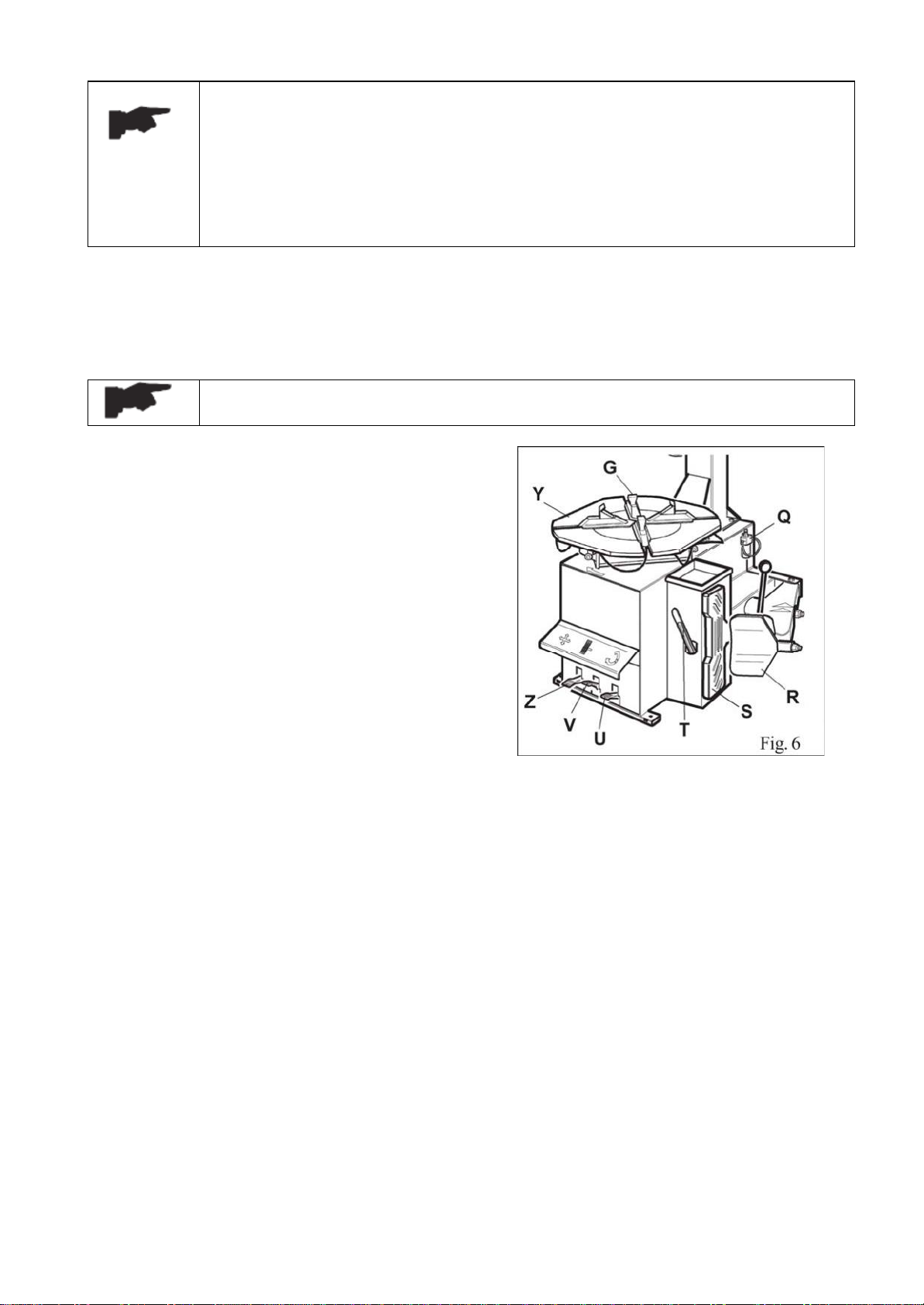
2.2 DESCRIPTION
G) Clamps
I) Mounting head
M) Mounting bar
N) Horizontal arm
P) Vertical arm
Q) Air supply
R) Bead breaker
S) Wheel support
T) Bead lifting lever
U) Bead breaker control pedal
V) Clamp control pedal
Z) Reverse control pedal
Y) Turntable
K) Locking lever
Fig . 1
7 / 32
REV. 01
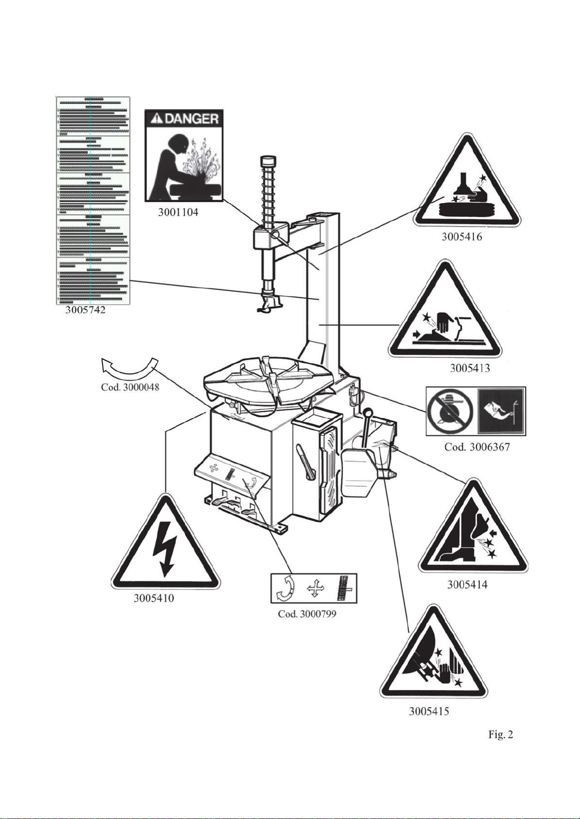
2.3 DANGER WARNING SIGNS

8 / 32
REV. 01
2.4 TECHNICAL SPECIFICATION
External locking rim dimension
12” –26”
13” –27”
14” –28”
Internal locking rim dimension
14”- 28”
15” –29”
16” –30”
Max. tire diameter
1200mm (47.5”)
Max tire width
470mm(18.5”
)
Force on bead breaker blade (10 bar)
2500 kg
Working pressure
8 bar (116 psi)
Inflating pressure device max.
3.5 bar (50 psi)
Power supply voltage
230V-1Ph
110V-1Ph
Motor power
0.75KW (230V -1Ph single speed)
1.1KW (110V -1Ph single speed)
Rotating speed
7 –14
rpm
Max spindle torch
1200 NM
Dimension
1140 x 1100 x 950
Net weight
240 kg STND
Noise level in working condition
< 70 dB (A)

9 / 32
REV. 01
CHAPTER 3 –TRANSPORTATION,UNPACKING AND STORAGE
3.1 TRANSPORTATION
•
The tire changer must be transported in its original packaging and kept in the position shown
on the package itself.
•
The packaged machine may be moved by means of a forklift truck of suitable capacity. Insert
the forks at the points shown in figure 3.
3.2 UNPACKING
•
Remove the protective cardboard and the nylon bag.
•
Check that the equipment is in perfect condition, making sure that no parts are damaged or
missing. Use fig. 1 for reference.
If in doubt do not use the machine and contact your retailer.
3.3 STORAGE
In the event of storage for long periods of time, be sure to disconnect all sources of power and grease
the clamp sliding guides on the turntable to prevent them from oxidizing.
10 / 32
REV. 01
CHAPTER 4 –INSTALLATION
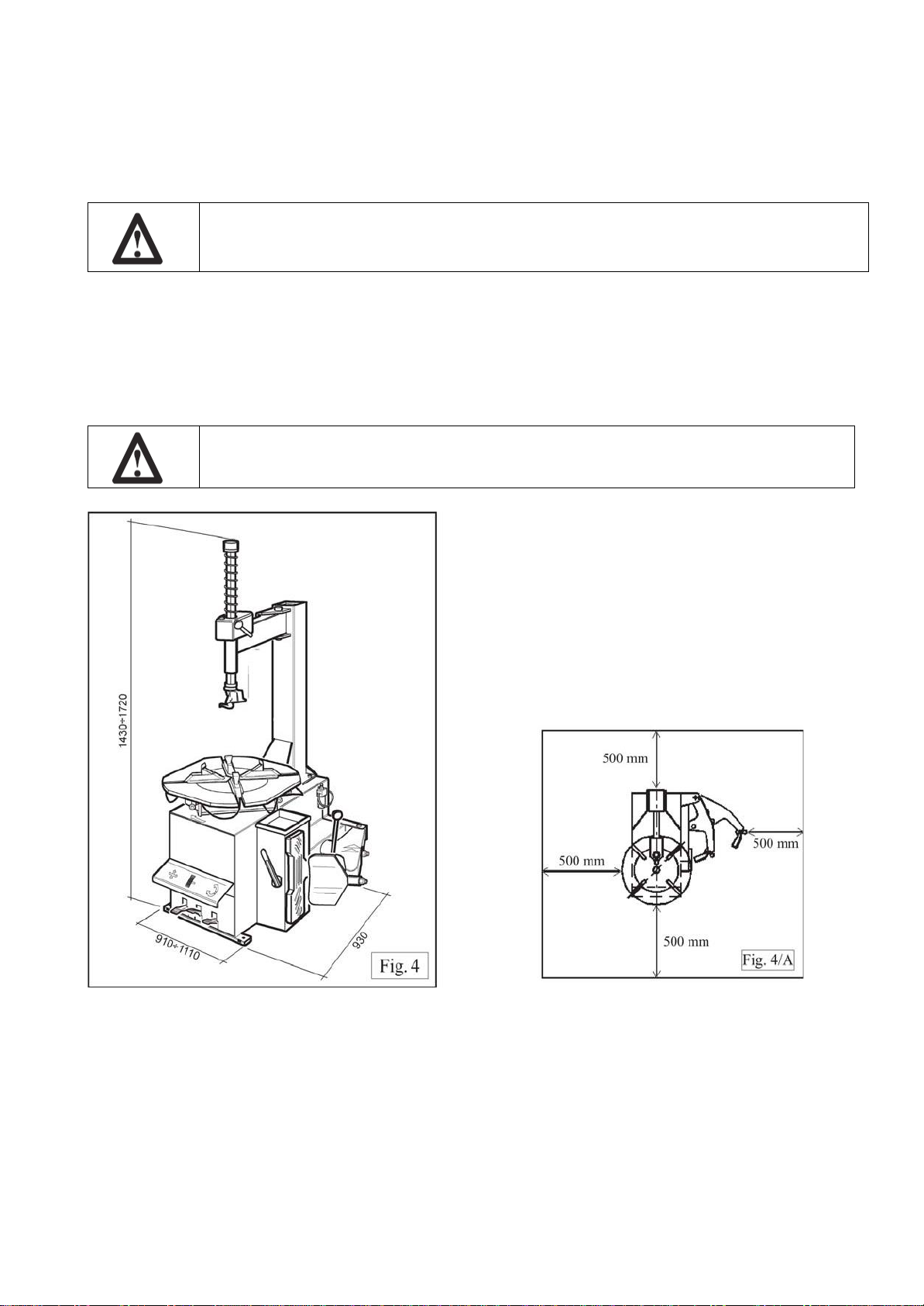
4.1 SPACE REQUIRED
When choosing the place of installation be sure that it complies with current safety
at work regulations.
•
The tire changer must be connected to the main electric power supply and the compressed air
system. It is therefore advisable to install the machine near the corresponding sources.
•
The place of installation must also provide at least the space shown in pictures 4 - 4/A, to allow
all parts of the machine to operate correctly and without any restriction.
This tire changer with electric motor cannot be used near explosive materials.

11 / 32
REV. 01
4.2 POSITIONINGANDPARTS ASSEMBLY
4.2.1 Arm assembly and peripherals
•
Remove the pallet fixing screws and set the tire changer on the floor.
•
Unscrew the 4 screws from the body, set the vertical arm into the proper seat and fasten the 4
screws firmly with a wrench (Fig. 5/a).
•This operation must be performed by two operators. A crane or similar equipment may be required
to safely lift the vertical arm.
•
Proceed to screw in the knob that serves as a ‘Stopper” into the base of the
horizontal arm. Swing the horizontal arm from left to right back and forth,
adjust if necessary, the nut as shown in Fig. 5/b.
Before connecting all the power sources ALWAYS check your installations.
They must exactly correspond to those requested by the machine.

12 / 32
REV. 01
•
Connect the pneumatic quick connect male plug corresponding to the shop’s air supply (hose)
onto the filter assembly. Use a sealant such as Teflon tape to avoid air leaks. Connect the shop’s air
supply to the Quick connect adapter, as shown below (Fig. 5/d). Keep the air flow off until the
machine is ready for operation.
•
Connect the hose coming out from the back of the machine into the fitting located at the bottom
of the vertical column. Slide the hose onto the fitting and then fasten the clamp.
•
Insert the knob/pin assembly into the desired position of the bead breaker

13 / 32
REV. 01
•
Insert the ring provided in the accessory box into the left side of the tire changer’s body. Place
the container provided for lubricant inside the ring.
4.2.2 Mounting and connecting the manometer
•
Remove the top screw and loosen the bottom screw from the plate that holds the manometer
assembly. Mount the manometer assembly and fasten with both screws. Connect the pneumatic line into
the union on the back of the machine.
14 / 32
REV. 01
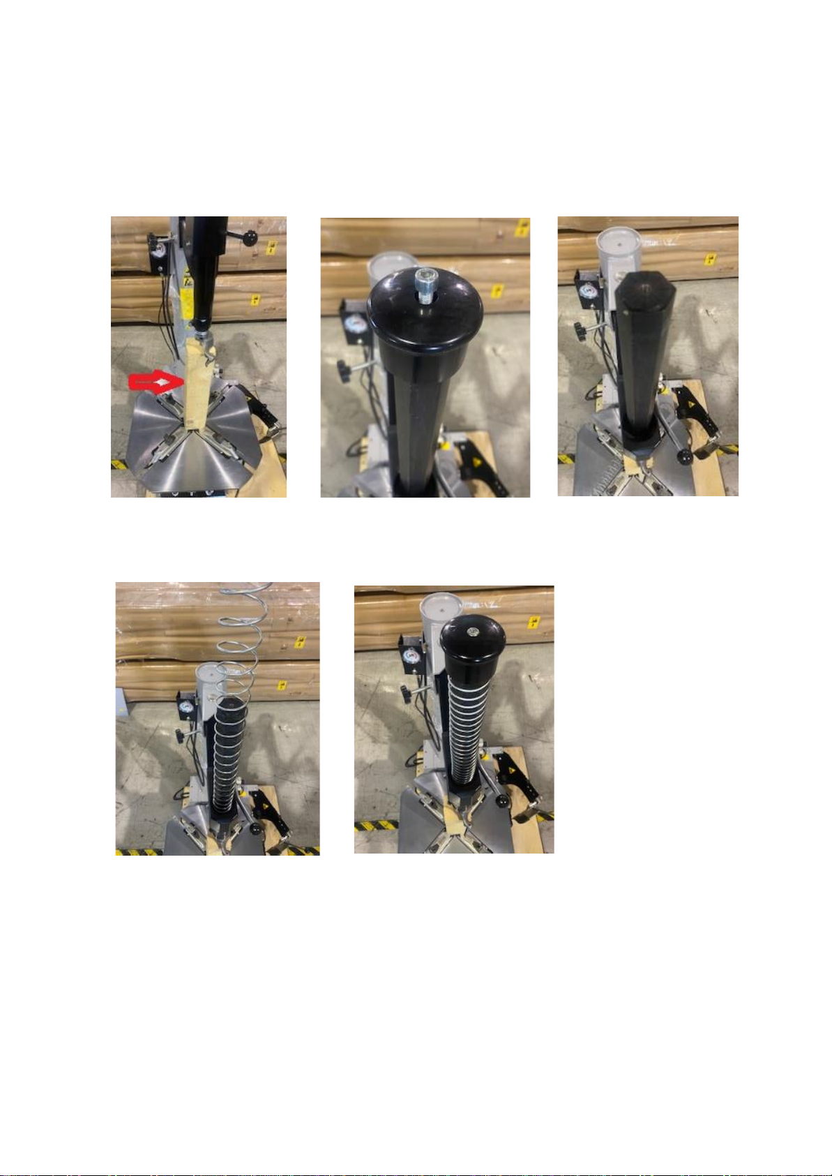
4.2.3 Installing the spring in mount/demount arm
•
Lift by hand the mount/demount arm and place a wedge (wood, etc.) to hold in place. Remove
the screw the holds the plastic cap and remove the cap completely.
•
Insert the spring provided in the accessory box. Place the plastic cap and fasten with a hex
wrench.

15 / 32
REV. 01
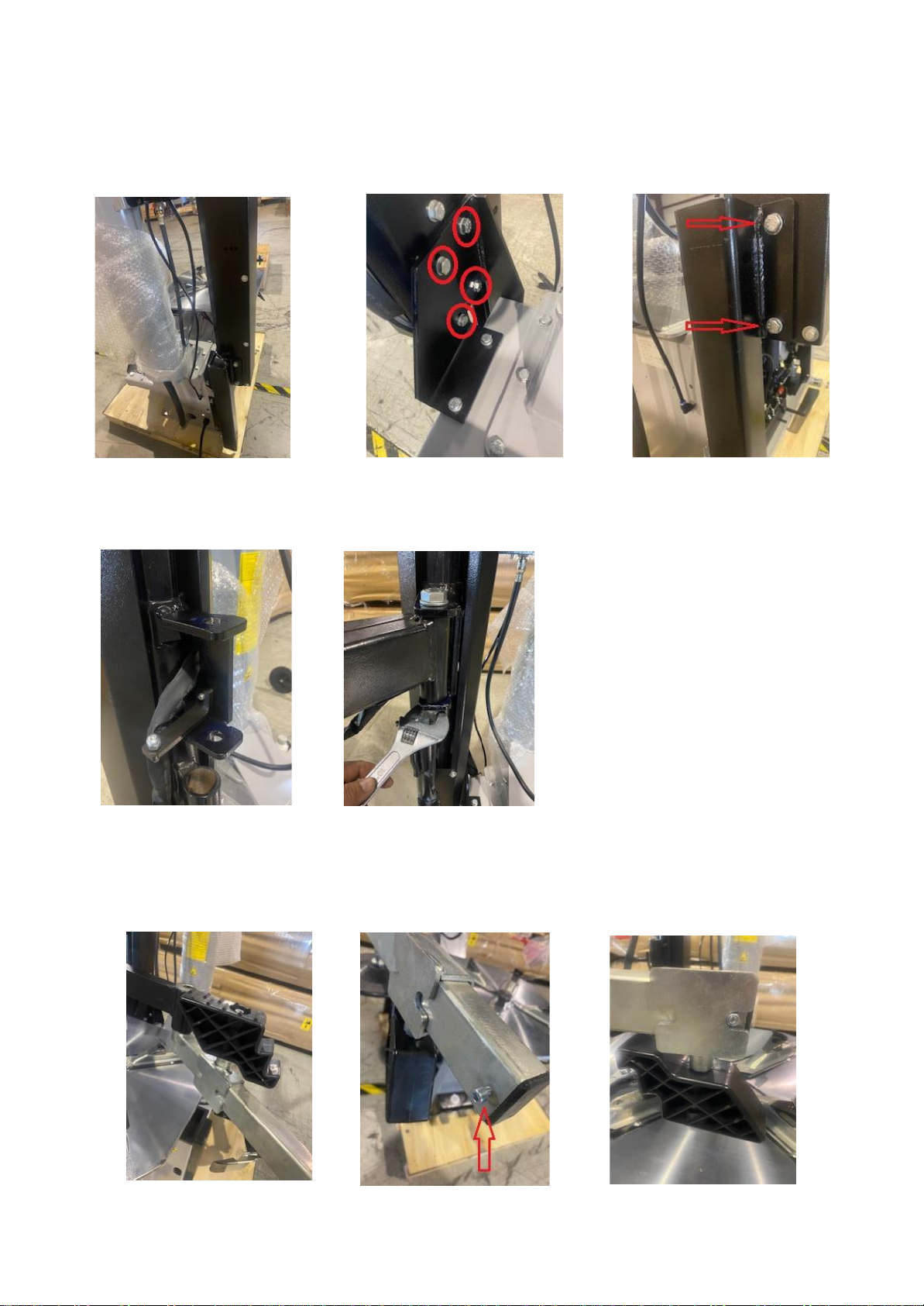
4.2.4 Assist arm assembly (Optional)
•
Remove the screws around the perimeter of the side cover on the right side of the machine. Place
cover aside to gain access to the inside of the machine.
•
Mount the side support of the assist arm onto the chassis of the tire changer (right rear corner).
Fasten the 3 screws with a wrench.
•
Mount the side bracket of the assist arm on top of the tire changer chassis. Fasten the screws (2)
against the chassis with a wrench
16 / 32
REV. 01
•
Install the Assist arm’s body. Fasten the assist arm body onto the side bracket using 2 long screws
and 2 short screws. Insert metal bracket into the assist arm from the bottom and fasten with 2 screws
using a wrench.
•
Install the Assist arm. Fasten the bolt on the assist arm support through the assist arm itself.
•
The hard-plastic foot comes in mounted in reverse. Remove the screw that acts as a stopper for
the “foot”, slide out the “foot” from the arm, rotate 180 degrees and re-insert. Fasten the screw again.
17 / 32
REV. 01
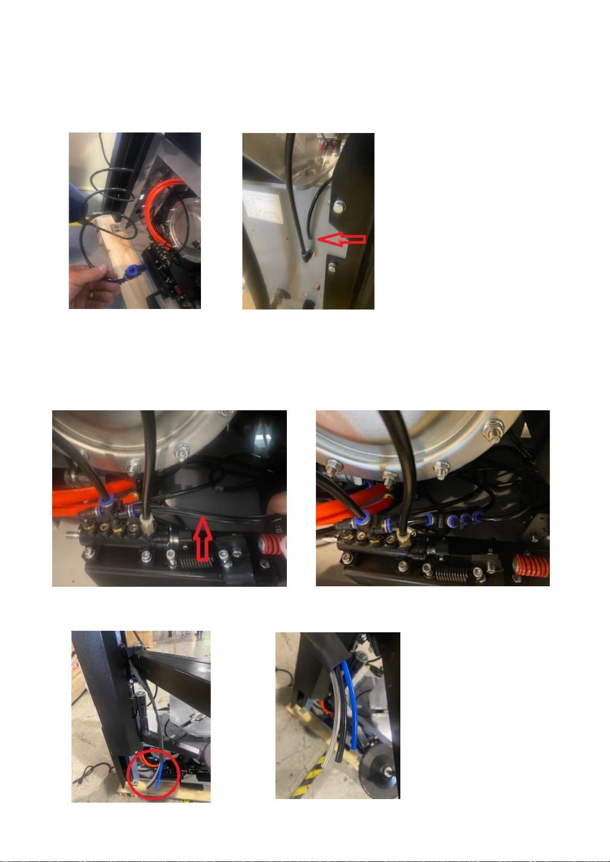
•
Pull out the pneumatic hose and valve that are rolled inside the assist arm’s body. Disconnect the
valve and route the hose through the hole in the back of the machine, as shown below. Reconnect the
valve inside the machine.
•
Splice the pneumatic hose coming out from the main valve assembly located inside the machine.
Splice the hose approximately 3”-4” away from the valve, as marked with a red arrow below. Connect the
pneumatic valve that came from the assist arm in-between the two hoses that were spliced, as shown
below.
•
Identify the pack of pneumatic hoses (clear, black & blue) coming from the assist arm.
18 / 32
REV. 01
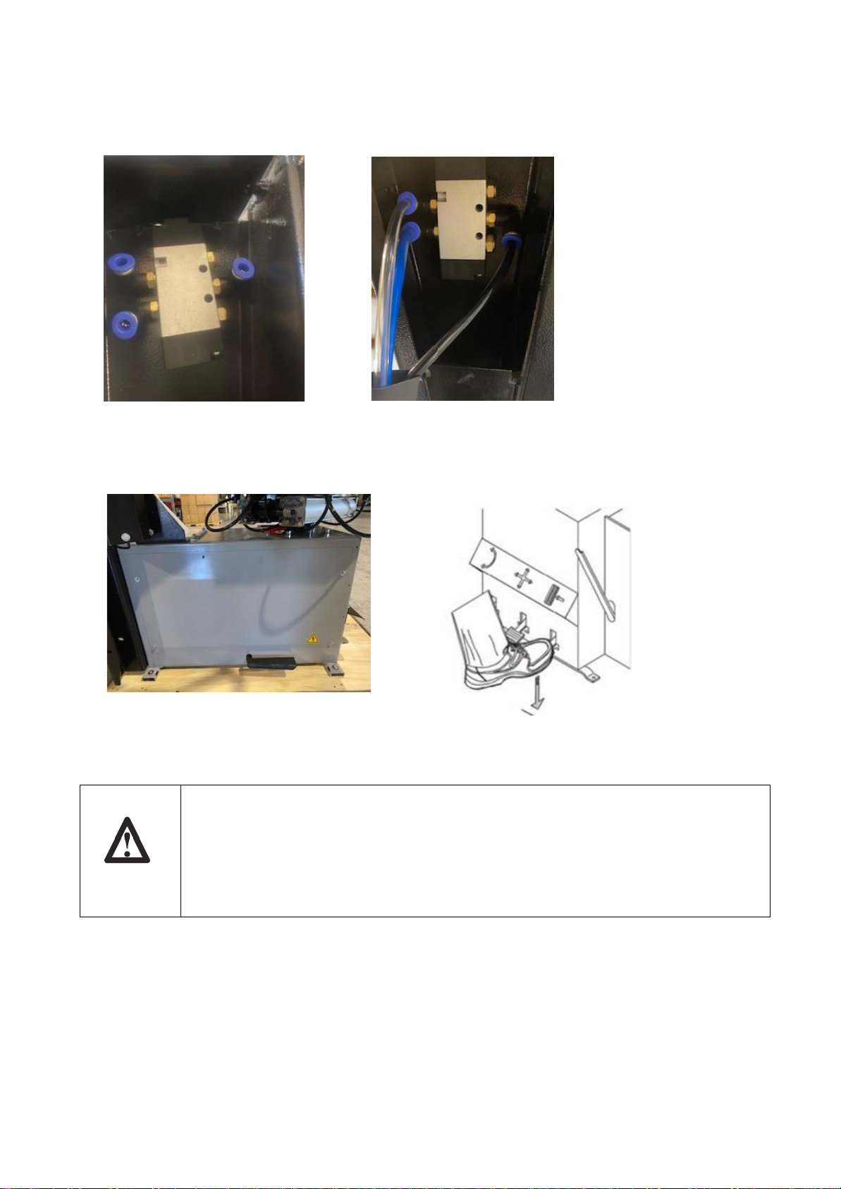
•
The pack of pneumatic hoses must be connected into the control valve located under up/down
lever of the assist arm. Proceed to connect the blue, clear and black hoses as shown in the pictures below
•
Mount the side door back onto the machine and proceed to test the machine as described in the
following steps.
4.3 COMMISSIONING
Any electric connection job must be carried out by professional and
qualified personnel.
Make sure that the power supply is correct.
Make sure the connection of the phases is right. Improper electrical hook-up
can damage the motor and will not be covered under warranty.
•
Check to make sure that the characteristics of your system corresponds to those required
by the machine. If you have to change the machine’s operating voltage, make the necessary
adjustments to the terminal board referring to the electric diagram in chapter 9.
•
Connect the machine to the compressed air system.
19 / 32
REV. 01
Connect the machine to the electric network, which must be equipped with line
fuses, thepropergroundplate in compliance with OSHA regulations and it must be
connected to an automatic circuit breaker (differential) set at 30 mA.
Should the user need to provide a different electric plug, please ensure that it is rated
at least for 16 Amps.
4.4 OPERATING TESTS
•
When pedal (Z) is pressed down the turntable (Y) should turn in a clockwise direction. When
pedal is pulled up the turntable should turn in an anticlockwise direction.
If the turntable turns in the opposite direction to that shown, reverse two of the
wires in the tree-phase plug.
•
Pressing the pedal (U) activates the bead
breaker (R); when the pedal is released the bead
breaker returns to its original position.
•
Pressing the pedal (V) opens the four clamps
(G); when the pedal is pressed again, they close.
•
Pressing the trigger on the airline gauge, will
cause air to be released from the head.

20 / 32
REV. 01
4.4.1 GT VERSION
Do NOT LEAN on the turntable during this operation. Dust on turntable could
reach the operator’s eyes. For that reason, be careful as not to accidentally push
the inflating pedal while working.
•
When the pedal located on the left side of the machine
body is pushed down to its intermediate position (B),
air is released from the airline gauge.
•
When the pedal (C) is pushed down completely, air is
released from the airline gauge with a powerful jet from
the nozzles located in the turntable clamps.
4.5 TURNTABLE LOCKING VALUE ADJUSTING
Fig. 13
The tire changer turntable is preset by the manufacturer on a middle range measure from 12”to 28”
ext. (considering the rim outer side and) from 14”–30” int. (if you lock the rim from inner side).
It is however possible to change this dimension range in case of need when working on larger or
small rims; it is enough to change the position of the 4 clamps are shown in the figures below.
The obtainable value starts from a minimum of 12”-26” ext. and 14”-28” int. until a maximum of 14”-
28” ext. and 16”-30” int.
To change the position, proceed as follows:
•
Unscrew screw (1) using an Allen wrench.
•
Remove the locking clamp (2) and the slide piece (3).
•
Align the slide hole with one of the guide holes (4) according to the locking dimensions you
want to set. Use the measurements below for reference.
It is important to perform the above-mentioned operation for all 4 clamps to
avoid any unbalance in the locking process.
Table of contents
Popular Service Equipment manuals by other brands


Garmat
Garmat 99270 Installation, operation & maintenance manual

Speed Clean
Speed Clean BucketDescaler Operating & maintenance instructions

Bosch
Bosch WBE 4200 Repair instructions

Sealey
Sealey VS0041 instructions

Seville Classics
Seville Classics UltraHD 20210 Assembly instructions

Desco
Desco 07710 Operation installation and maintenance