7708, 7709 2 rev. 09/02/15
WARNING INFORMATION
This is the safety alert symbol. It is used to alert you
to potential personal injury hazards. Obey all safety
messages that follow this symbol to avoid possible
injury or death.
IMPORTANT: READ THESE INSTRUCTIONS BEFORE OPERATING
BEFORE USING THIS DEVICE, READ THIS MANUAL COMPLETELY AND THOROUGHLY, UNDERSTAND ITS OPERATING
PROCEDURES, SAFETY WARNINGS AND MAINTENANCE REQUIREMENTS.
It is the responsibility of the device owner to make sure all personnel read this manual prior to using the device. It is also the responsibility
of device owner to keep this manual intact and in a convenient location for all to see and read. If the manual or product labels are lost or
not legible, contact Sunex for replacements. If the operator is not fluent in English, the product and safety instructions shall be read to
and discussed with the operator in the operator’s native language by the purchaser/owner or his designee, making sure that the operator
comprehends its contents.
THE NATURE OF HAZARDOUS SITUATIONS
The use of car dollies is subject to certain hazards that cannot be prevented by mechanical means, but only by the exercise of intelligence,
care, and common sense. It is essential to have personnel involved in the use and operation of the device who are careful, competent, trained,
and qualified in the safe operation of the device and its proper use when servicing motor vehicles and their components. Examples of hazards
are dropping, tipping or slipping of loads caused primarily by improperly securing loads, overloading, off-centered loads, use on other than
hard level surfaces, and using equipment for a purpose for which it was not intended.
METHODS TO AVOID HAZARDOUS SITUATIONS FOR CAR DOLLY
• Read,study,understandandfollowallinstructionsbeforeoperatingthisdevice.
• Useofthisproductislimitedtotransportingonly.
• Dolliesmustbeusedinpairs.Dolliesaretobeusedtosupportvehicles.Donotusetosupportvehicleswithoutwheels.
• Inspectthedollybeforeeachuse.Donotuseifdamaged,altered,modied,inpoorcondition,leakinghydraulicuid,orunstabledueto
loose or missing hardware or parts. Make corrections before using.
• WeareyeprotectionthatmeetsANSIZ87.1andOSHAstandards.
• Donotexceedratedcapacity.
• Useonlyonhard,level,dryconcretesurfacefreefromexpansionjointsandallobstructions.
• Donotusewithtiresthatarewiderthan12".
• Beforemovingthevehicle,ensurethatthevehiclewheelsarecenteredandsecure.
• Donotstartthevehicle’sengineordrivethevehiclewhenmountedondollies.Thedollyisdesignedformanuallymovingthevehicle.
• Activatethecasterlockingdevicesaftermovingavehicle.
• Donotuse(ormodify)thisproductforanyotherpurposethanthatforwhichitwasdesignedwithoutconsultingthemanufacturer's
authorized representative.
• Neverworkon,around,orunderavehiclesupportedbycardollies.
• ThisproductmaycontainoneormorechemicalsknowntotheStateofCaliforniatocausecancerandbirthdefectsorotherreproductive
harm. Wash hands thoroughly after handling.
• Failuretoheedthesewarningsmayresultinseriousorfatalpersonalinjuryand/orpropertydamage.
METHODS TO AVOID HAZARDOUS SITUATIONS FOR CAR DOLLY RACK
• Read,study,understandandfollowallinstructionsbeforeoperatingthisdevice.
• Inspecttherackbeforeeachuse.Donotuseifdamaged,altered,modied,inpoorcondition,orunstableduetolooseormissing
hardware or parts. Make corrections before using.
• WeareyeprotectionthatmeetsANSIZ87.1andOSHAstandards.
• Donotexceedratedcapacity.
• Useonlyonhard,level,dryconcretesurfacefreefromexpansionjointsandallobstructions.
• Usethisrackforitsintendedpurposeofstoringandtransportinguptofourdolliesonly.
• Donotuse(ormodify)thisproductforanyotherpurposethanthatforwhichitwasdesignedwithoutconsultingthemanufacturer's
authorized representative.
• ThisproductmaycontainoneormorechemicalsknowntotheStateofCaliforniatocausecancerandbirthdefectsorotherreproductive
harm. Wash hands thoroughly after handling.
• Failuretoheedthesewarningsmayresultinseriousorfatalpersonalinjuryand/orpropertydamage.
WARNING: Indicates a hazardous situation
which, if not avoided, could result in death
or serious injury.
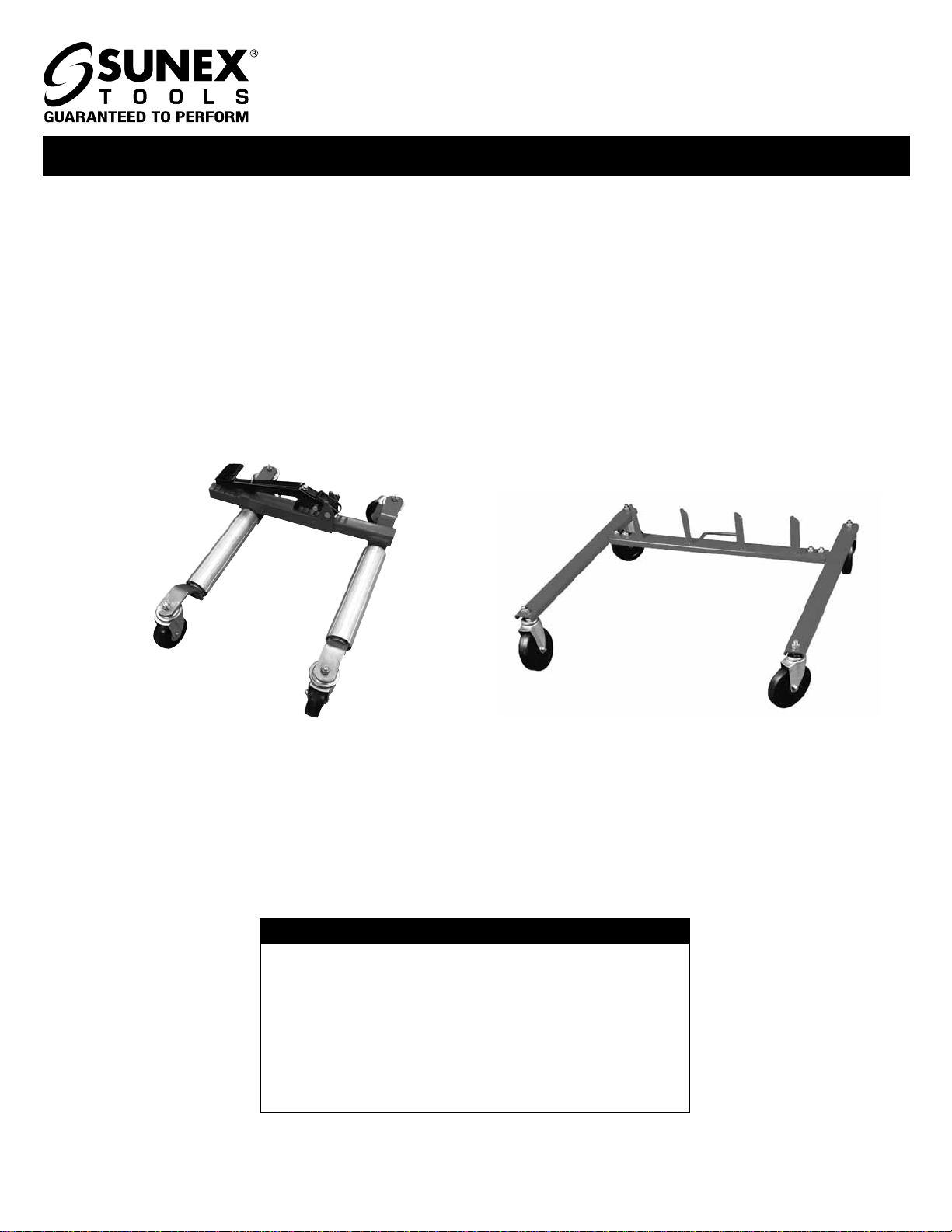
OPERATING MANUAL & PARTS LIST FOR 7708, 7709
WARNING
WARNING
WARNING
WARNING