Garmat 99270 Instruction manual

FOR YOUR SAFETY
If You Smell Gas:
1. Open Window
2. Don't Touch Electrical Switches
3. Extinguish Any open Flame.
4. Immediatly Call Your Gas
Supplier
The use ans storage of gasoline or
other flammable vapors and liquids
in open containers in the vicinity of
this appliance is hazzardous.
WARNING: Improper installation,
adjustment. alteration, service or
maintenance can cause property
damage, injury or death. Read the
installation, operating and
maintenance instructions throughly
before installing or servicing this
equipment.
NOT FOR RESIDENTIAL USE.
FOR YOUR SAFETY
1

Garmat®USA, Models 99270, 99273,
& 99275 Direct Gas-Fired Industrial
Heater
HEATER DESCRIPTION
The Garmat®USA, Inc. heater is a
direct gas-fired fresh-air appliance. It is
designed for indoor installation, outdoor
installation with the proper sheltering
from weather, with fresh outdoor air
delivered to the combustion zone. The
heater is designed for use with natural
gas or LPG ( check the heaters' rating
plate). The direct gas-fired burner will
modulate to maintain the selected air
discharge temperature. This appliance is
most suited for use with spray paint
booths and associated equipment. It
does, however, fill the need for non-
recirculating building air make up.
INSTALLATION CODES
This equipment is designed and
manufactured to provide years of safe
and efficient operation. In order to retain
these features, The installer (s) need to
achieve certain installation and operation
requirements. These requirements will
be defined throughout this manual and
should be specifically noted.
The type of fuel used with this
equipment and it’s proper firing rate are
shown on the appliance rating plate.
Electrical characteristics are shown on
the rating plate as well. If the need for a
change in fuel type occurs, the
manufacturer must be consulted.
WARNING: THIS UNIT IS NOT
FOR INSTALLATION ON
COMBUSTIBLE MATERIALS.
THIS UNIT IS TO BE INSTALLED
ON CONCRETE OR OTHER NON
COMBUSTABLE SURFACES.
WARNING: CLEARANCE
AROUND THE UNIT TO
COMBUSTIBLES SHOULD BE NO
LESS THAN 4” (FOUR INCHES).
This equipment shall be installed in
accordance with the standards of the
National Fire Protection Association and
the National Fuel Gas Code ( NFPA 54
).
Local authorities having jurisdiction
must be consulted first to verify local
codes and installation procedures. In the
absences of such codes and installation
procedures, the unit shall be installed in
accordance with the National Fuel Gas
Code ANSI Z223.1 - Latest addition.
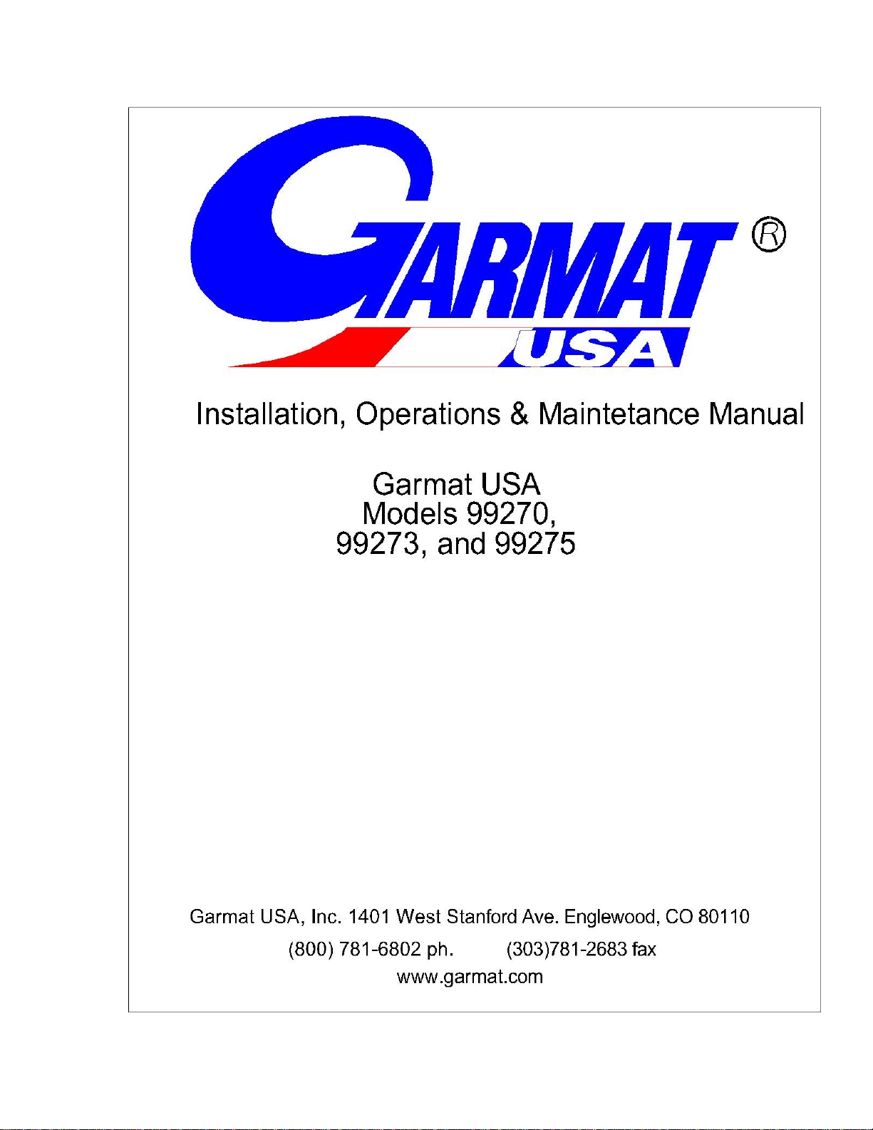
HEATER INSTALLATION:
CONFIGURATION AIR BOX
INSTALLATION
The Garmat®USA air make up units are
equipped with a configuration air box
(“C” box). This “C” box needs to be
attached to the top of the make up unit
utilizing 3/4” number 8 self drilling
screws. The screws should be sent
through the framing of both the unit and
the “C” box to ensure it’s security.
2
ROOF TOP INSTALLATION
The Garmat®USA air make up units are
not designed as exterior structures.
NOTE: GARMAT® USA INC, DOES
NOT RECOMMEND
INSTALLATION OF THE
HEATING UNIT OUTDOORS.
INDOOR SUSPENSION
MOUNTING
A support system must be made by
installers to support the entire air make
up unit. It is recommended that this
support system be suspended by 1/2” -
13 threaded rod (or greater).
WARNING: IF SERVICE
PLATFORM IS REQUIRED,IT IS
THE INSTALLERS
RESPONSIBILITY. IF PLATFORM
IS ADDED, ADDITIONAL WEIGHT
MUST BE ADDED TO TENSILE
STRENGTH. REQUIREMENTS
FOR BUILDING STRUCTURE.
CAUTION: DURING
INSTALLATION, VIBRATION
ISOLATION SHOULD BE
INSTALLED TO PREVENT
TRANMISSION TO THE
BUILDING STRUCTURE.
BELTS & DRIVES
After unit is connected to utilities and is
ready for start up, install fan belts and
sheaves. Adjust for proper belt tension.
Proper tension is achieved when the belt
can be depressed 1/2” with moderate
pressure at mid point between the motor
and the fan sheves.
The Garmat®USA, Inc. air make up
unit comes with solid bushing mounted,
and variable sheaves. If adjustment to
air through-put is needed, the vairable
sheaves can be adjusted. Always check
motor amperages to ensure that loads
stay within the motors’ electrical plate
ratings. Failure to do so will void motor
warranty. After adjustments are made,
the variable sheaves must be secured
with thread lock.
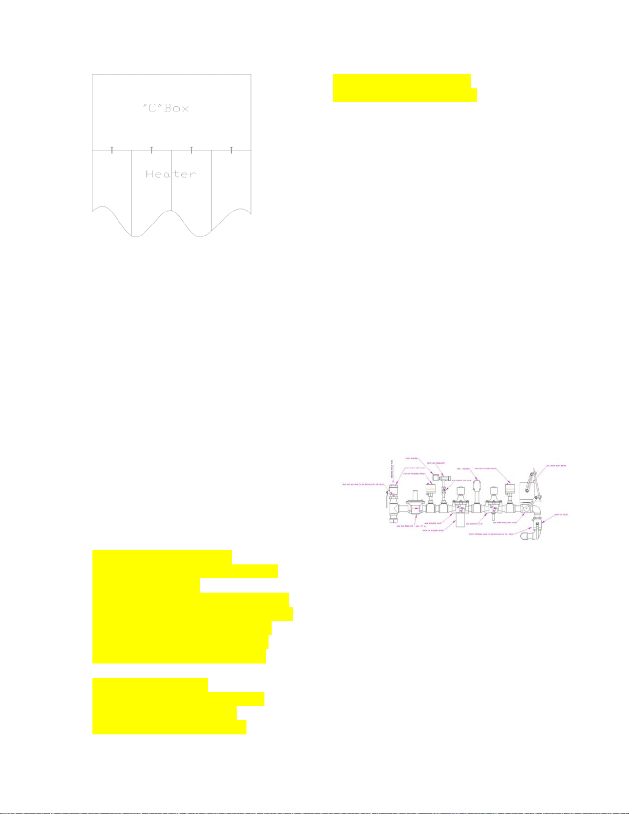
GAS MANIFOLD
The Garmat®USA, Inc. air make up
units are equipped with one manifold
designed to meet IRI requirements.
The gas train of the air make up unit is
suitable for connection to supply
pressures from 21” WC maximum to 7”
WC minimum for natural gas and 5”
WC maximum to 3” WC minimum for
propane (LPG). Capacity for both types
of fuel are to provide input to specified
3

burner size. Model 99270 have 0.84
MBTU burner. Model 99273
has a 1.0 MBTU burner and model
99275 has a 1.5 MBTU burner.
The gas pipe connection size for the
model 99270 will be 1” and for the
models 99273 and 99275 will be 1 1/4”.
A drip leg or trap at the inlet of the gas
manifold is provided.
WARNING: PIPING MUST BE
ADDED IN ORDER TO INSURE
GAS TRAIN VENT IS PIPED TO
THE OUTSIDE OF BUILDING.
FAILURE TO DO SO WILL CAUSE
GAS TO VENT INTO THE
BUILDING AROUND THE
MANIFOLD.
WARNING: ALL COMPONENTS
OF THE GAS SUPPLY SYSTEM
MUST BE LEAK TESTED PRIOR
TO PLACING EQUIPMENT INTO
OPERATION.
ELECTRICAL:
WARNING: SPARK TESTING OR
SHORTING OF THE CONTROL
WIRES BY ANY MEANS WILL
DAMAGE THE CONTROL PANEL
AND VOID THE WARRANTY.
All electrical wiring and connections,
including electrical grounding, should be
made in accordance with the National
Electric Code ANSI/NFPA 70 current
addition.
Although the Garmat®USA, Inc. air
make up units are for use in most
commercial heating applications, the
main application of the unit is for use
with a paint spray booth. The use of two
120 volt 20 ampere circuits for lighting
will need to be supplied to the unit when
used in conjunction with a paint spray
booth.
The motor requirements are as follows:
for 3 PH, 10 HP units, 208 volt AC
requires 30.8 Full Load Amperage
“FLA”, 230 volt AC requires 28 FLA
and 460 volt requires 14 FLA. For
single phase, 10 HP motors 230 volt AC
requires 50 FLA. The single phase
motors are not available and a roto-phase
inverter or buck booster is required and
not provided by Garmat USA®.
For Three Phase 15 HP units, 208 volt
AC requires 46.2 FLA., 230 volt AC
requires 42 FLA., 460 volt AC requires
21 FLA. The single phase motors are not
available.
For control voltage a transformer is
provided to convert the motor voltage to
the proper control voltage/s.
NOTE: ALL MOTOR AMPERAGE
FIGURES ARE BASED ON NEC.
LOCAL REQUIREMENTS MAY
VARY.
WARNING: ELECTRICAL AND
IGNITION SYSTEMS MUST BE
PROTECTED FROM DRIPPING
WATER. IMPROPER
INSTALLATION, ADJUSTMENT,
ALTERATION, SETRVICE, OR
MAINTENANCE CAN CAUSE
PROPERTY DAMAGE, INJURY OR
DEATH. READ THE
INSTALLATION, OPERATING
AND MAINTENANCE
INSTRUCTIONS THOROUGHLY
BEFORE INSTALLING OR
SERVICING THIS EQUIPMENT.
SAFETY SYSTEM
4

Manual High Limit ( All models )
If any situation occurs creating a
temperature reaching 200° F at the air
discharge, power to the gas train
circuitry will be terminated. At this point
none of the operating components of the
gas train will function. To reactivate the
gas train the reset button on the limit
switch must be depressed. The main
application of this heater is for use with
a paint spray booth and a additional high
limit thermostat is provided for use in
the spray mode to shut down the gas
train if the discharge air temperature
reaches 165 deg. F. This high limit is
automatically resetting.
Air Flow Sensor ( All models )
Air flow sensors are connected directly
to the flame guard device.When a loss or
lack of air flow, or to much air flow
across the burner is sensed, the flame
guard device will terminate power to the
pilot solenoid and the connection of the
temperature controller to the gas train
modulator. The through-put air around
the burner will need to be reestablished,
or reduced for the burner to fire.
Flame Guard Device ( All models )
The flame guard is a device that will
check the burner for pilot during
initiation and for pilot and main flame
during full operation. The flame guard
device uses a flame rod installed in the
burner which will thermally induce a 15
- 18 volt DC signal in the flame guard
device. During initiation there is a 10
second trial period. At the end of this
time if there is no flame in the pilot area,
the flame guard will lock out the burner
system. The flame guard will need to be
manually reset to start initiation. It does
not re-attempt initiation automatically.
The flame guard is a “one try” system
that will require manual reset each time
the device locks out. When a flame
depletes or disappears in the burner
during full operation, the flame guard
will have a 10 second delay and will
lock out the burner system. The flame
guard will need to be manually reset at
this point.
Temperature Control System
( Models 99270 )
The system uses an analog temperature
controller with analog input and a 100%
symmetrically modulating gas valve.
The thermister connected to the
temperature control will be placed in the
air output of the make up air unit. The
temperature controller internally limits
the discharge temperature to 170° F
when shipped. The manual high limit
will act as a back up to this.
Temperature Control System
( Models 99273 and 99275 )
This system uses a digital temperature
controller, a 100% modulator and a
symmetrically modulating gas valve.
The thermocouple connected to the
temperature control will be placed in the
air output of the make up air unit. The
temperature controller internally limits
the discharge temperature to 190° F
when shipped. The manual high limit
will act as a back up to this.
FREEZE THERMOSTAT
( All Models )
5

In areas where the ambient temperature
can fall below –20 deg. F, it is
recommended that a low temperature
limit control (freeze thermostat ) be
installed (not provided by Garmat
USA®. The low temperature control
shall be installed in series with the high
limit switch in the gas train safety
circuit.
High Gas Pressure Switch
( Models 99273 and 99275 )
This component is on the gas manifold
and will disconnect electrical power to
the gas train circuit before reaching the
flame guard device. In the event that
more than 21” WC of gas pressure enters
the gas manifold at this point, the switch
will disconnect the power and will need
to be manually reset.
Low Gas Pressure Switch
( Models 99273 and 99275 )
This component is on the gas manifold
and will disconnect electrical power to
the gas train circuit before reaching the
flame guard device. In the event that less
than 3” WC of gas pressure enters the
gas manifold or pressure drops below
this point, the switch will disconnect the
power and will automatically reset when
pressure is restored.`
Proof Of Closure Switch
( Models 99273 and 99275 )
This switch is mounted directly under
one of the blocking valves on the gas
train and is linked to the valve actuator
and proves that the valve is closed
before allowing electrical power to
continue through the gas train circuit.
Cabin Pressure Control System
( Model 99270 )
A manual ¼ adjust lever is provided at
the exhaust pressure damper. A slack
tube manometer is provided for
montering the cabin pressure.
( Models 99273 and 99275 )
The remote control panel contains a
photohelic gauge. This gauge is
displayed on the face of the remote panel
and controls the air pressure within the
cabin. This gauge is adjustable using the
two orange needles visible on the face of
the gauge. The gauge operates a
modulating motor attached to exhaust
pressure damper. Opening the cabin will
cause loss of cabin air pressure.
PROGRAMMABLE LOGIC
CONTROLLER ( PLC )
( All Models)
The electrical panel contains a
programmable logic controller ( PLC ).
The PLC controls all of the automatic
functions of the control sequence
including flash-off time duration, bake
time duration and cool down time
duration. Bake time duration is set at the
remote panel on the 99270 deluxe,
99273, 99275 models. On the model
99270 the bake timer is internal in the
PLC. Flash-off time duration and cool
down time duration are internal
functions of the PLC and are set at the
factory. The factory setting of the flash-
off time duration is three minutes and for
the cool down time duration is ten
minutes. These time durations can be
reset by your authorized local authorized
distributor.
6

OUTDOOR VENTILATION AIR
( All Models )
Outdoor air must be ducted to the air
make up unit inlet when unit is installed
inside of a building. This ducting shall
be no smaller than 30” square or the
equivalent in crossectional surface area
in diameter of round ducting. Bends or
transitions are not recommended and
length should be kept to less than 5
meters or 16.5 feet. If bends or
transitions are required, turning vanes
are recommended.
LINE PRESSURE TEST
( All Models )
The make up unit and its inlet manual
gas valve must be disconnected from gas
supply piping during any pressure
testing above 21” WC. The air make up
unit must be isolated from the gas supply
system by closing the manual gas valve
up stream of the regulator on the inlet of
the gas manifold.
PROPER SEQUENCE OF
OPERATION
The Garmat®USA Inc. air make up unit
can be ordered with several different
usage options. To simplify the sequence
of operations, all four available options
will be covered.
There are four modes of operation:
Power On, Run or Spray, Recycle or
Bake and Shut Down.
Power On
( Models 99273 & 99275 )
The three phase voltage supplies power
to the control transformer. The 120, and
24 volt is connected through the control
transformer. When the power switch and
spray switch are actuated, power is given
to the motors. If either exhaust fan motor
starter or the supply motor starter trips
out on overload the respective motor and
make up unit operations will cease until
respective motor starter is reset. Both
control voltages are protected with
breakers in the main electrical panel.
A 120 volt jumper is provided in the
main control panel which can be
connected through a NC contact on a
micro switch used for a fire suppression
system.
When The NC contact is opened, the 120
volt control supply is removed from the
circuit and the entire unit shuts down.
The EM (Emergency stop) switch on the
remote control panel does the same.
Rotating the EM switch reconnects the
120 volt supply, unless the fire system
has not been reset.
The green light will illuminate when the
EM switch is rotated clockwise. The 120
volt control power is connected through
the EM switch in the remote control
panel. If either motor starter trips out on
overload, a red light will illuminate for
the respective motor and make up unit
operations will cease until respective
motor starter is reset. Both control
voltages are protected with breakers in
the main control panel.
Run or Spray
( Models 99270 and 99270-E )
With the OFF switch on the spray cycle
can be started by pushing the SPRAY
switch. The air make up will run in the
7

spray mode until it is switched to either
the OFF switch or the BAKE switch is
pushed. The SPRAY mode provides 120
volt to the PLC, which in turn supplies
120 volt to starter SM2 and the
temperature controller in the remote
control panel. SM2 is present for
controlling an exhaust motor. As soon as
SM2 is energized, 120 v power is
supplied to SM1 through the PLC after a
timed delay. SM1 is provided for
controlling the motor contained within
the air make up unit and a timed delay
will still be present to delay start up.
SM1 allows 120 volt power to be
supplied to the green light for the supply
motor and the burner thru the PLC. Both
are located on the remote control panel.
When the burner switch is set to the
winter position, 120 volt power is
provided to the PLC, which supplies 120
volt power to the gas train power circuit.
When the burner switch is in the summer
position the gas train power circuit will
not be energized in the SPRAY mode.
Bake
( Models 99270 )
With the OFF switch on and the SPRAY
switch on Placing the BAKE switch in
BAKE provides 120 volt power through
the PLC internal bake timer. For the
99270 deluxe model the bake timer is
located on the face of the remote panel.
The BAKE switch supplies 120 volt
power to the PLC in the main control
panel, which begins the delay cycle. The
purge timer should be set for a minimum
of 3 minutes. At the completion of the
delay cycle, 120 volt power is supplied
to the change over damper solenoid. In
turn, the change over damper is opened
pneumatically releasing the damper air
valve. When the damper valve is
released, the change over damper
solenoid is energized, the compressed air
solenoid is de-energized. The lighting
circuit is also removed from 120 volt
supply. This drops out the lighting and
compressed air source for spray. The
PLC supplies 120 volt power to the gas
train power circuit.
In bake the PLC places the temperature
controller in the second set point or 2SP.
This is the bake mode setting.
At the end of the programmed bake time,
whether 1 or 999 minutes, the PLC
initiates the shut down mode.
Shut Down
The bake timer initiates the timed shut
down mode. The supply to the change
over solenoid is also restablished. The
change over damper closes. The lights
come back on and the temperature
controller returns to the first set position,
SP. If burner switch is in the summer
position, the PLC will shut off the gas
train circuit.
At the end of the timed cool down cycle
(1 to 10 minutes), all functions of the
unit will shut down completely, with the
exception of the lights. The PLC
interrupts the 120 volt power to the
exhaust fan, the intake fan and the
burner circuit. The lights in the booth
will remain “on” until switched off. The
PLC will hold the unit in the “off” status
until the power is interrupted to the
system by pushing the OFF switch to
“off” and back “on”.
Bake
( Models 99273 and 99275 )
8

Placing the OFF-SPRAY-BAKE switch
in BAKE provides 120 volt power
through the PLC to the bake timer
located on the remote control panel and
power to the change over damper
solenoid. The timer will begin the timing
sequence. The bake timer should be set
in the “C” mode on the left of the timer
face and the “M” mode on the right. “M”
is for minutes.
The bake delay timer supplies 120 volt
power to the PLC in the main control
panel, which begins the delay cycle. The
bake delay timer should be set for a
minimum of 5 minutes. At the
completion of the delay cycle, 120 volt
power is supplied to the change over
damper solenoid. In turn, the change
over damper is opened pneumatically
releasing the damper air valve. When the
damper valve is released, the
compressed air solenoid is de-energized
and the lighting circuit is removed from
120 v supply. This drops out the lighting
and compressed air source. The PLC
supplies 120 volt power to the gas train
power circuit.
The PLC places the temperature
controller in the second set point or 2SP.
This is the bake mode setting.
At the end of the programmed bake time,
whether 1 or 999 minutes, the PLC
initiates the shut down mode.
Shut Down
The bake timer initiates the timed shut
down mode. The supply to the change
over solenoid is also interrupted. The
change over damper closes. The lights
come back on and the temperature
controller returns to the first set position,
SP. When the burner switch is in the
summer position, the PLC shuts off the
gas train circuit.
At the end of the timed cool down cycle
(1 to 10 minutes), all functions of the
unit will shut down completely. The
PLC interrupts the 120 volt for all
components, including the exhaust fan,
intake fan, and burner circuit and holds
the unit in an “off” status until the
OFF/SPRAY/BAKE switch is set to the
OFF position. The shut down mode can
be interrupted at any time by switching
the unit to Spray.
GAS TRAIN POWER CIRCUIT
( Models 99270 )
With the OFF switch on and the SPRAY
switch in the SPRAY position and the
burner is in the WINTER position, or if
the BAKE switch is in the BAKE
position the PLC provides 120 volt
power through the Manual High Limit.
This allows 120 volt power to be
provided to the Flame Guard Device.
The Flame Guard Device starts a 7
second delay before ignition. When this
time delay is finished, both the ignition
transformer and the pilot solenoid are
energized. If the flame rod in the burner
provides proof of flame to the Flame
Guard Device, the ignition transformer is
shut down and the normally open vent
valve is closed and the main gas valves
open. After the main gas valves have
opened, the PLC closes the circuit
between the temperature control and the
gas manifold modulating valve.
If the Flame Guard Device does not
receive proof of flame in the burner
within 10 seconds, the pilot solenoid and
the ignition transformer will be de-
energized. The Flame Guard Device will
shut down the gas train.
9

The burner green light is denergized on
the remote control panel. The Flame
Guard Device will need to be manually
reset to start the process over.
GAS TRAIN POWER CIRCUIT
( Models 99273 and 99275 )
When the OFF-SPRAY-BAKE switch is
in the SPRAY position and the burner is
in the WINTER position, or if the OFF-
SPRAY –BAKE switch is in the BAKE
position the PLC provides 120 volt
power to the Low Gas Pressure Switch.
The 120 volt power continues to the
High Gas Pressure Switch and proceeds
to the Proof of Closure Switch,
continuing to the Manual High Limit.
All of these components must allow the
120 volt power to be provided to the
Flame Guard Device. When the 120 volt
power reaches the Flame Guard Device
it passes through directly to the High Air
flow Sensor and the Low Air Flow
Sensor. The Air Flow Sensors prove air
flow and the Flame Guard Device starts
a 7 second delay before ignition. When
this time delay is finished, both the
ignition transformer and the pilot
solenoid are energized. If the flame rod
in the burner provides proof of flame to
the Flame Guard Device, the ignition
transformer is shut down and the
normally open vent valve is closed and
the main gas valves are opened. After
the valves are open, the PLC closes the
circuit between the temperature control
and the gas manifold modulating valve.
If the Flame Guard Device does not
receive proof of flame in the burner
within 10 seconds, the pilot solenoid and
the ignition transformer will be de-
energized. The Flame Guard Device will
send a signal to the PLC. The PLC
switches the 120 volt power from the
burner green light to the burner red light
on the remote control panel. This also
de-energizes the gas train power circuit.
The Flame Guard Device will need to be
manually reset to start the process over.
COMPRESSED AIR FOR SPRAY
APPLICATION WITHIN BOOTH
( All Models )
A solenoid is provided to control the
compressed air source in a paint spray
booth. It is located in the main control
panel. 120 v power is provided to the
solenoid through the PLC to the exhaust
pressure switch, door air switch and
return air switch. The make up unit must
be in the Spray mode for compressed air
to be provided to the spray booth.
CHECK, TEST, START UP
PROCEDURES
( All Models )
CAUTION: HIGH VOLTAGE
PRESENT IN PANEL
Before Start Up
1. Inspect roof caps, inlet, and outlet of
the air make up unit for any debris that
can block airflow.
2. With multimeter, test motor voltages
to assure that they agree with the tag on
the unit. In addition, test the lighting
voltage. Make sure that the breakers at
the building panel and/or the fuse in the
disconnect match the amperage ratings
on the makeup units’ information tag.
3. Inspect the burner to assure that the
assembly is tight and in the proper place.
Inspect the flame rod, ignitor and pilot
10

gas tube for tightness and good
connection. Make sure that the air flow
sensor tube is tight and well connected.
4. Perform gas pressure test at test port
on inlet manual gas valve and assure that
the maximum pressure listed on the unit
information tag is not exceeded. In
addition, check that there is enough gas
pressure and capacity for burner size.
5. Check all gas lines and gas manifold
for leaks.
6. Double check all electrical
connections to the unit.
Start Up
1. Bump start the motors and check for
proper rotation. Correct rotation if
necessary.
2. Connect amp probe to motor circuits
and turn unit on. Document amperages
for each power leg and date. Assure that
motors are within their motor plate
amperage ratings. Leave documentation
in the control panel and send copy with
warranty information to manufacturer.
3. Install gas pressure gauges on the on
manual gas valves of the gas train. After
unit is up and running, turn burner on.
While waiting for gas train safety to
complete it’s cycle, turn burner manifold
manual gas valve off. When ignition
sequence has completed and pilot flame
is present, use the pilot orifice on the gas
manifold to adjust the pilot flame to
approximately four (4) inches in height,
or the size of a fist. If a freeze thermostat
is install for extremely cold climates,
( below -20 deg. F. ) the burner will not
start if the temperature across the burner
is below –20 deg. F.
4. Adjust high fire setting by viewing
gas meter at the test port on the burner
manifold manual gas valve.
Set the temperature controller on the
remote control panel to the manual
setting and set output to 100 %. Open
the burner manifold manual gas valve
long enough to acquire reading and close
the valve. The pressure should be 4.2”
WC minimum and should not exceed
5.2” WC maximum. Adjust regulator if
necessary and test again. Set temperature
controller back to 0.0 % output and open
output manual gas valve.
5. Adjust the burner ribbon with the
temperature control in the manual setting
and set to 0.0 % output. Viewing the
burner, adjust the zero increase
potentiometer in the top of the gas
manifold modulating motor. Adjust the
zero increase until a small flame is
ribboning across the bottom of the
burner trough. When adjustment is
correct, set temperature control back to
the auto setting. Increase and decrease
the temperature setting on the
temperature control to check for proper
operation.
6. Set the bake timer to 5 minutes. On
99270 model push the SPRAY and the
BAKE switches. On the 99273 and
99275 units set the OFF/SPRAY/BAKE
switch to the BAKE position. Wait for
change over to occur. After 3 minutes
the dampers should change over to
recycle. When the bake timer times out,
the cool down cycle will begin. The
entire unit should shut down after the
cool down cycle is complete.
7. Test air through- put and change
sheaves if necessary.
11

MAINTENANCE INSTRUCTIONS
( All Units )
1. Motor bearings should be lubricated at
4 month intervals.
2. Drive belts should be adjusted at least
two times during the first two hours of
operation. Adjust for 1/2 inch deflection
with medium pressure at middle of belt
span. Belts should be replaced annually.
3. Blower wheel should be periodically
inspected for build up of dust or dirt and
cleaned if necessary.
4. Annually check the burner and
components. The flame rod should be
changed annually.
5. The air flow sensing switch and
tubing should be checked periodically
for obstructions or debris.
6. The metallic inlet air filters should be
cleaned in 4 month intervals. Observe
the air flow direction indication on the
filter frame when reinstalling.
12

TROUBLE SHOOTING CHART
SYMPTOM POSSIBLE CAUSE ACTION RECOMMENDED
NOTHING WORKS EM switch is off. Incoming 1 PH Turn EM switch on. Check
(GREEN POWER LIGHT voltage is off. The 120 volt for incoming 3 phase voltage.
IS NOT ON) control breaker in main panel Reset breaker in main
is tripped. control panel.
NOTHING WORKS Overload relay is tripped. loss Reset overload relay. Check
(RED POWER LIGHT of phase. Low 3 phase voltage. for 3PH. Measure 3PH
IS NOT ON) voltage.
EVERYTHING WORKS Lighting breaker(s) tripped. Reset lighting breaker(s).
EXCEPT BOOTH LIGHTS Change over damper stuck Check change over damper.
open Control air is off. Ensure control air is set at
40-60 PSI.
TEMPERATURE DOES NOT Outside air temperature is Increase set point on
RISE (BURNER GREEN greater than set point. Temperature control. Reset
LIGHT IS ON) High limit is tripped. Low gas high limit. Check low and
Pressure. High gas pressure. High gas switches. Check
Proof of closure switch is open. Proof of Closure switch. If
problem persists call an
authorized Garmat® service
technician.
TEMPERATURE DOES NOT Pilot has failed during ignition Push red reset button on
RISE ( BURNER RED LIGHT cycle. Pilot manual gas valve red box marked Fireye.
IS ON. Turned off. Turn manual pilot valve on.
If lockout continues , call
Garmat® authorized service
Technician.
TEMPERATURE TOO HIGH Controller set in second set point. Check temperature
DURING SPRAY MODE. Outside temperature above 70 º controller display. Set burner
Fahrenheit. Switch to summer setting.
13
This manual suits for next models
2
Table of contents
Other Garmat Service Equipment manuals


Popular Service Equipment manuals by other brands

Magneti Marelli
Magneti Marelli ATF EXTRA PRO user manual

Hyundai
Hyundai Midtronics GRX-5100 instruction manual

Tronair
Tronair 01-1229-0011 Operation & service manual

ULTIMATE SPEED
ULTIMATE SPEED HG02236 Assembly and Safety Advice

CEMB
CEMB DWA1000CWAS manual

Invacare
Invacare TDX SP Assembly, installation and operating instructions


