INSTRUCTION, USE AND
MAINTENANCE MANUAL
GB
Page 2 of 98
7505-M002-4_B
NAV41.11N - NAV41T.11N - NAV41.13N - NAV41T.13N -
NAV41.13EI - NAV41T.13EI - NAV41.13SA - NAV41T.13SA
SUMMARY
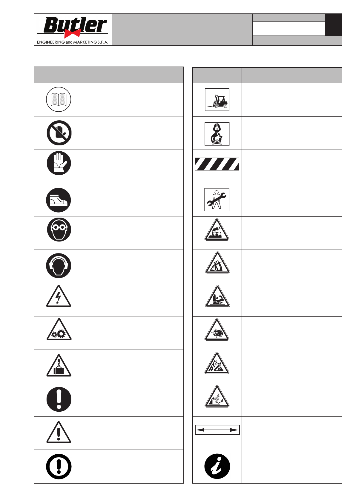
SYMBOLS USED IN THE MANUAL AND
ON THE MACHINE_______________________ 8
1.0 GENERAL INTRODUCTION ________ 11
1.1 Introduction _________________________ 11
2.0 INTENDED USE ___________________ 11
2.1 Training of personnel________________ 11
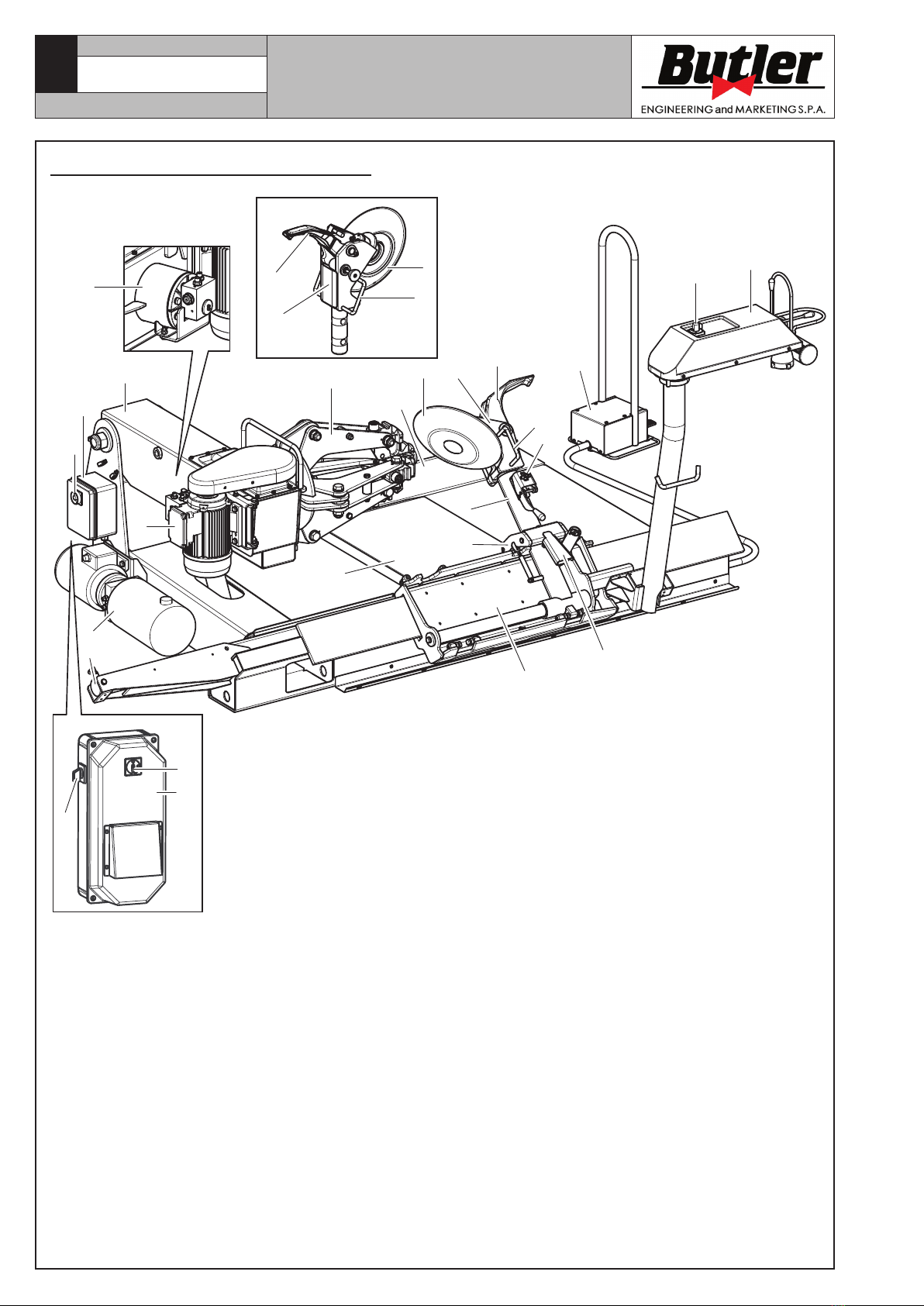
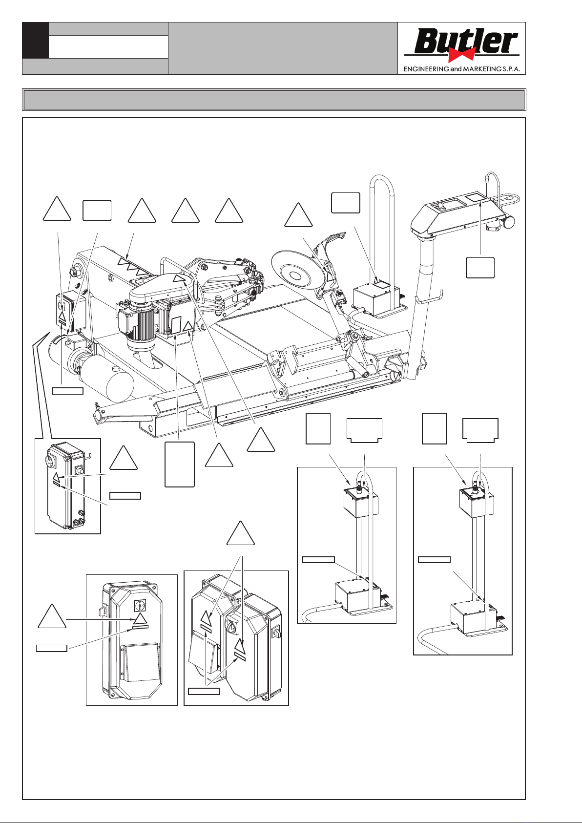
3.0 SAFETY DEVICES _________________ 12
3.1 Residual risks _______________________ 13
4.0 GENERAL SAFETY RULES ________ 13
5.0 PACKING AND MOBILIZATION FOR
TRANSPORT ______________________ 14
6.0 UNPACKING _______________________ 14
7.0 MOBILIZATION____________________ 14
8.0 WORKING ENVIRONMENT
CONDITIONS ______________________ 15
8.1 Working position ____________________ 15
8.2 Installation space ___________________ 15
8.3 Lighting _____________________________ 15
9.0 MACHINE ASSEMBLY _____________ 15
9.1 Anchoring system ___________________ 15
9.2 Accessories contained in the packing _ 16
10.0 ELECTRICAL CONNECTION _______ 16
10.1 Oil check on oil-pressure power unit _ 17
10.2 Check of motor rotation direction ___ 17
10.3 Electrical checks ____________________ 17
11.0 CONTROLS________________________ 19
11.1 Control device (valid for NAV41.11N,
NAV41T.11N, NAV41.13N and
NAV41T.13N models) ________________ 19
11.2 Control device (optional for
NAV41.11N, NAV41T.11N, NAV41.13N
and NAV41T.13N models) ____________ 19
11.3 Control device (only for NAV41.11N,
NAV41T.11N, NAV41.13N, NAV41T.13N
models with VARGNAV4113D version
with inverter) _______________________ 20
11.4 Control device (valid for NAV41.13EI
and NAV41T.13EI models) ___________ 21
11.5 Control device (valid for NAV41.13SA
and NAV41T.13SA models) __________ 21
12.0 USING THE MACHINE _____________ 22
12.1 Precaution measures during tyre
removal and fitting__________________ 22
12.2 Preliminary operations ______________ 22
12.3 Preparing the wheel _________________ 22
12.4 Wheel clamping______________________ 22
12.5 Functioning of tool holder arm ______ 24
12.5.1 Tools rotation ___________________ 25
12.6 Tubeless tyres _______________________ 27
12.6.1 Bead breaking___________________ 27
12.6.2 Demounting _____________________ 28
12.6.3 Mounting ________________________ 30
12.7 Tyres with inner tube________________ 33
12.7.1 Bead breaking___________________ 33
12.7.2 Demounting _____________________ 33
12.7.3 Mounting ________________________ 34
12.8 Wheels with bead wire_______________ 36
12.8.1 Beading and demounting ________ 37
12.8.2 Mounting ________________________ 38
13.0 ROUTINE MAINTENANCE _________ 39
14.0 TROUBLESHOOTING TABLE ______ 41
15.0 TECHNICAL DATA_________________ 43
15.1 Technical data -
NAV41.11N - NAV41T.11N____________ 43
15.2 Technical data NAV41.13N -
NAV41T.13N _________________________ 43
15.3 Technical data NAV41.13EI -
NAV41T.13EI ________________________ 43
15.4 Technical data NAV41.13SA -
NAV41T.13SA________________________ 44
15.5 Dimensions __________________________ 45
16.0 STORING__________________________ 49
17.0 SCRAPPING _______________________ 49
18.0 REGISTRATION PLATE DATA _____ 49
19.0 FUNCTIONAL DIAGRAMS _________ 49
Table A - Pneumatic diagram (NAV41.11N -
NAV41T.11N - NAV41.13N -
NAV41T.13N) ____________________ 50
Table B - Pneumatic diagram (Optional)
(NAV41.11N - NAV41T.11N -
NAV41.13N - NAV41T.13N) _______ 54
Table C - Electric diagram (NAV41.13EI -
NAV41T.13EI)____________________ 58
Table D - Electric diagram (NAV41.13SA -
NAV41T.13SA) ___________________ 65
Table E - Electric diagram (NAV41.11N
monophasic version
220V 60Hz)______________________ 72
Table F - Electric diagram
(VARGNAV4113D)________________ 73