BECKWITH ELECTRIC M-6280A User manual

Instruction Book
M-6280A Digital
Capacitor Bank Control

Digital Capacitor Bank
Control M-6280A
Digital Capacitor Bank Control for Remote Capacitor
Automation, Monitoring and Protection
CONTROLS
•Maximum Communication Options For Wired or
Wireless Networks
• RS-232, RS 485, & Serial Fiber Optic (ST orV-Pin)
• Ethernet Over Copper or Fiber Optic @ 10/100
Base-T
• Embedded Bluetooth®, Class 1 (v2.0), 1Mbps, 128
bit encryption, up to 1/2 mile transmission (with
appropriate antenna)
• Supports DNP3.0 & MODBUS®Protocols
• Time sync via DNP3.0 SetTime Command
• No need for battery to back up clock
• DNP mapping templates to match SCADA historical
databases
• Sequence of Events (SOE) Recording Of Events -
Stores 132 events, ms time-stamped
• Oscillography Capture – Selectable 16, 32, or 64
samples per cycle. Captures sags, swells, CBEMA
events and sub-synchronous transients
• FULL DNP implementation –
Including DNP FileTransfer, multi-
addressing, unsolicited response,
source address validation
• Harmonics Detection, Recording,
Protection and Suppression with
Current andVoltageTripping
• DNP SCADA HeartBeat – Integrity
check of communications media
and/or Master. Fully programmable
• TRUE Ethernet – Full 10/100Mbps
auto-negotiable concurrent multi-
session and multi-protocol support
• Smart Flash SD Card Slot for
Quick (10 -15 second) Uploading of
Configurations, Settings, Firmware
Upgrades, and Supports Control
Cloning
• Setpoint Profile Switching (8 Profiles)
• Cyber Security – Authentication and
Multi Level Access Codes, Smart Flash
SD Card serves as Cyber Security
Hard-Key with Audit Log
• Data Logging Continuous Recording
– Data stored in non-volatile memory
requiring no battery backup
• DNP+Ethernet – Device Discovery
using CapTalk

–2–
M-6280A Digital Capacitor Bank Control
Standard Features
• Fourcontrolmodesofoperation:
–ClassicAutomatic(Voltage,optional
VArControloroptionalCurrentControl)
–AutoAdaptivemode(FixedorAveraging)
–Remote
–Manual
• Twooverridemodesofoperation:
–Temperature
–Time
• TimeDelay–DeniteandInverse
• Adjustable Maximum/Minimum Voltage
Limits
• NeutralUnbalancecurrentdetection
–Bank/SwitchFailed
–BankClosed
–BankOpen
–Supports200mAinputtocontrol
• SetpointProles(8)TriggerablebySCADA,
Seasonal (4), Above/BelowTemperature,
andReversePower
• User selectable Overvoltage limit/
Undervoltage limit and time delay for
remotecontrolsupervision
• AdjustablewarningtimersforClose/Open/
Re-close
• Adjustable Close/Open output pulse
duration
• Real-Time Metering of measured and
calculatedparameters
• VT Ratio Correction,VT and CT (Phase
andNeutral)Multiplier
• OperationsCounter(Congurable)
• ResettableOperationsCounterwithAlarm
• HarmonicAnalysisofVoltageandCurrent
Signals,uptothe31stplusTHD
• THD Voltage and Current Tripping and
Lockout
• DataLogging
• Remote/Auto-LocalManualswitch
• Outputs:Close,OpenandAlarm
• Minimum Time Between Operations
Delay
• 20 Character by 2 Row LCD display
(LEDbacklit)
• Upto30unique15characterUserAccess
Codes(Level1orLevel2)
• CBEMA monitoring to detect sags and
swells and trigger data collection and
alarmingfunctions
• SmartFlashSDCardSlotsupportingSD
andSDHCSDcards
• SmartFlashSDCardcanbelinkedtoone
or multiple controls providing a physical
security"Key"whichprovidesUserAccess
Level2AccesstothecontrolwhentheSD
Cardisinsertedforsettingsmanipulation
• SequenceofEvents(SOE)recorder
• DeviceDiscovery
• SourceAddressValidation
• Oscillography
• FrontPanelLEDsforRemote/Auto,Local
Manual, Alarm, Close, Open, OK, RSSI,
Neutral Unbalance, (TX) Transmit and
(RX)Receive
• ProgrammableAlarms
• Front Panel Hot Buttons provide direct
accesstomenuheaders
• FrontPaneltesting:
–Int/ExtVoltageSourceswitch
–ExternalPowerinputterminals
–MeterOutterminals
• Communication Protocols DNP3.0 and
MODBUS®
• Adaptive Delta Voltage sensing during
switchoperations
• DailyOperationsCounterLimit
• CapTalk® S-6280 Communications
Software
• Capacitor Bank switch status inputs for
phaseA,BandC
• Graphical display of real-time harmonic
spectrum of voltage and current using
CapTalkCommunicationsSoftware
• CommunicationPorts:
–USB
–RS-232
All brand or product names appearing in this document are the trademark or registered trademark of their
respective holders.

–3–
M-6280A Digital Capacitor Bank Control
Standard Features (Cont’d)
• SCADA"HeartBeat"(withDNP3.0only)
• Supports Station and Feeder Level
DNP addressing in addition to individual
addressingforSmartGridapplications
• Onepushbuttonaccesstousercongurable
Wakeupscreenformanualdatarecording
withSmartFlashSDCardsavingfeature
• Oneset(3)ofsparefusesareincluded
• CapacitorBankSwitchselection"Solenoid
Driven"or"MotorDriven"forClose/Open
PulseDuration
• 200mANeutralCurrentinputforNeutral
Unbalancedetection
• SCADATestMode
Optional Control Features
• Automatic VAr Control Mode options
include:
–5Aphasecurrentinput
–0to10VLinePostSensorinput
• LocalWirelessBluetooth®capabilityClass1
TypeBluetoothUSBAdapterthatsupports
wireless transmission up to 300 meters
(withanappropriateantenna)
• EthernetPort(10/100Base-T)isavailable
through a RJ-45 jack or Fiber Optic ST
Connector.This port supports DNP over
TCP/IPandUDP;MODBUSoverTCP/IP.
• 5 A Neutral Current input for Neutral
Unbalancedetection
• LinePostCurrentSensorinputforNeutral
Unbalancedetection
• CommunicationsPorts:
–STFiberOptic
–V-pinFiberOptic
–RS-485
• TheM-6280AcanbehousedinaNEMA
4 Molded Lexan®, Cold Rolled Steel or
Stainless Steel Control cabinet. (See
M-2980A section of this specication for
detailedinformation).

–4–
M-6280A Digital Capacitor Bank Control
CAPACITOR BANK CONTROL OPERATION
Control Modes of Operation
The control includes two standard modes of Automatic Voltage Control (Classic Voltage Control and
AutoAdaptiveVoltageControl),OptionalVAr ControlmodeandCurrent Controlmodeareavailable.
Classic Voltage Control Mode:The control will make its Open and Close switching decisions based on
measuredLineVoltageconditionsandTimeand/orTemperatureoverrideswhenapplied.Voltageexcursions
beyondthesetvalueforgreaterdurationthanthetimedelaywillresultinappropriatecontroloperation.
– Control OpenVoltage:Adjustablefrom95.0to140.0Vin0.1Vincrements
– Control Close Voltage: Adjustablefrom95.0to140.0Vin0.1Vincrements
– Close and OpenTime Delays:DeniteorInverse;adjustablefrom0secondsto600seconds,in1
secondincrements.Timerresetcanbeselectedasinstantaneousorintegrating.
– Time Override:IntheAutoControlModeaTimeOverridecanbeappliedtocapacitorbankOpen
andCloseoperations.TheTimeOverridefeatureconsidersStartDate,StartTime,EndDate,End
Time,Duration,RecurrencePatternandaRangeOfOccurrencestoimplementtheoverride.
– Temperature Override:IntheAutoControlModeaTemperatureOverridecanbeappliedtocapacitor
bank Open and Close operations.TheTemperature Override feature considers sensed ambient
temperature and implements override action (Open, Close or None) for either above or below
temperaturesetpointconditions.
NOTE: TimeandTemperatureOverridescanbeoverriddenbyControlModeLimits.
Auto AdaptiveVoltage Control Mode:Thisfeaturecontainstwocontrolmethods,FixedorAverage.TheFixed
methodprovidesaBandcentersettingthecontrolcomparestomeasurevoltagetoopenorclosetheCapacitor
bank.TheAveragemethodusesanEffectiveBandcenterbasedonalongtermaverageoftheinputvoltageto
comparetomeasurevoltagetoopenorclosethecapacitorbank.Bothmethodsemployaninversetimerand
Bandwidthtooptimizebankoperationandeliminateunnecessaryswitching.Also,Timeand/orTemperature
overridescanbeapplied.
– Fixed-Band Center:Adjustablefrom100.0to135.0Vin0.1increments
– Bandwidth (Multiple of DeltaV): Adjustablefrom1.0to2.0in0.1increments
– Close and Open Time Delays: Inverse only; adjustable from 60 to 3600 seconds, in 1 second
increments.Timerresetisxedasintegrating.
– Time Override:IntheAutoControlModeaTimeOverridecanbeappliedtocapacitorbankOpen
andCloseoperations.TheTimeOverridefeatureconsidersStartDate,StartTime,EndDate,End
Time,Duration,RecurrencePatternandaRangeOfOccurrencestoimplementtheoverride.
– Temperature Override:IntheAutoControlModeaTemperatureOverridecanbeappliedtocapacitor
bank Open and Close operations.TheTemperature Override feature considers sensed ambient
temperature and implements override action (Open, Close or None) for either above or below
temperaturesetpointconditions.
NOTE: TimeandTemperatureOverridescanbeoverriddenbyControlModeLimits.
*OnlyavailablewithVArandCurrentControlModeoption.

–5–
M-6280A Digital Capacitor Bank Control
*OnlyavailablewithVArandCurrentControlModeoption.
Automatic VAr Control Mode Option*:ThecontrolwillmakeitsOpenandCloseswitchingdecisionsbased
onmeasuredlineVArconditionsandTimeand/orTemperatureoverrideswhenapplied.VArexcursionsbeyond
thesetvalueforgreaterdurationthanthetimedelaywillresultinappropriatecontroloperation.Thecontrolcan
beorderedwitheithera5ACTorLinePostCurrentSensorinputstoprovidephasecurrentmeasurementto
thecontrol.
– Control OpenVArs:–100%to100%ofsingle-phasecapacitorBanksizein1%increments
– Control Close VArs: 0%to100%ofsingle-phasecapacitorBanksizein1%increments
– Close and Open Time Delays: Denite or Inverse; adjustable from 0 seconds to 600 seconds,
in1secondincrements.Timerresetcanbeselectedasinstantaneousorintegrating.
– Time Override:IntheAutoControlModeaTimeOverridecanbeappliedtocapacitorbankOpen
andCloseoperations.TheTimeOverridefeatureconsidersStartDate,StartTime,EndDate,End
Time,Duration,RecurrencePatternandaRangeOfOccurrencestoimplementtheoverride.
– Temperature Override:IntheAutoControlModeaTemperatureOverridecanbeappliedtocapacitor
bank Open and Close operations.TheTemperature Override feature considers sensed ambient
temperature and implements override action (Open, Close or None) for either above or below
temperaturesetpointconditions.
NOTE: TimeandTemperatureOverridescanbeoverriddenbyControlModeLimits.
Automatic Current Control Mode Option*:Thecontrolwillmakeitsswitchingdecisionsbasedonmeasured
LineCurrentconditionsandTimeand/orTemperatureoverrideswhenapplied.Currentexcursionsbeyondthe
setvalueforgreaterdurationthatthetimedelaywillresultinappropriatecontroloperation.Thecontrolcanbe
orderedwitheither5ACTorLinePostSensorinputstoprovidephasecurrentmeasurementtothecontrol.
– Control Open Current:Adjustablefrom10to600Amps
– Control Close Current: Adjustablefrom10to600Amps
– Close and Open Time Delays: Denite or Inverse; adjustable from 0 seconds to 600 seconds,
in1secondincrements.Timerresetcanbeselectedasinstantaneousorintegrating.
– Time Override:IntheAutoControlModeaTimeOverridecanbeappliedtocapacitorbankOpen
andCloseoperations.TheTimeOverridefeatureconsidersStartDate,StartTime,EndDate,End
Time,Duration,RecurrencePatternandaRangeOfOccurrencestoimplementtheoverride.
– Temperature Override:IntheAutoControlModeaTemperatureOverridecanbeappliedtocapacitor
bank Open and Close operations.TheTemperature Override feature considers sensed ambient
temperature and implements override action (Open, Close or None) for either above or below
temperaturesetpointconditions.
NOTE: TimeandTemperatureOverridescanbeoverriddenbyControlModeLimits.
Remote Control Mode: Inthismode,thecontrolreceivescommandsthroughcommunicationsforClosingor
OpeningoftheCapacitorBank.
Remote Control Mode Limits: These limits can be disabled or enabled. If control operation will result
involtageoutsideoftheselimitsoperationwillbeblockedandnoticationwillbesenttothesender.If
measuredvoltageisoutsideoftheselimits,thecontrolwillinitiate anoperationinthedirectiontoreturn
voltagewithinlimits.
– Overvoltage Limit:Adjustablefrom95.0to140.0Vin0.1Vincrements
– Undervoltage Limit: Adjustablefrom95.0to140.0Vin0.1Vincrements
– Voltage Limits Timer:DeniteorInverse;adjustablefrom0secondsto600seconds,in1second
increments.Timerresetcanbeselectedasinstantaneousorintegrating.

–6–
M-6280A Digital Capacitor Bank Control
Control Mode Limits:Ifcontroloperationwillresultinvoltageoutsideoftheselimits,operationwillbeblocked.
Ifmeasuredvoltageisoutsideoftheselimits,thecontrolwillinitiate anoperationinthedirectiontoreturn
voltagewithinlimitsafterthesettimedelay.Onlytheblock andnottheinitiate operationisimplementedin
remotemanualmodeduetopersonnelsafetyconsiderations.Thesecontrolmodelimitscanbe;"DisableAll",
"EnableinAuto","EnableinRemote","EnableinManual".Anycombinationof"EnableinAuto","Enablein
Remote"and"EnableinManual"canbeselected.Theselimitswillapplyregardlessofthecontrolmodeof
operationselectedprovidingvoltageoverridefunctionalityinalloperationalmodes.
– MaximumVoltage Limit:Adjustablefrom95.0to140.0Vin0.1Vincrements
– MinimumVoltage Limit:Adjustablefrom95.0to140.0Vin0.1Vincrements
– DefiniteTime:Adjustablefrom0to60secondsin1secondincrements
Local Manual Mode:InthismodethecontrolwilldisableAutomaticandRemoteControlmodes.Inthismode,
thecontrolwillrespondtothefrontpanelCLOSE/OPENswitchposition.
Bank Operational Delays:
– MinimumTime Between Operations:Adjustablefrom0to3600secondsin1secondincrements
– CloseWarning Delay:Adjustablefrom0to90secondsin1secondincrements(Enable/Disable)
– OpenWarning Delay:Adjustablefrom0to90secondsin1secondincrements(Enable/Disable)
– Re-Close Delay:Adjustablefrom300to600secondsin1secondincrements
– Close/Open Pulse Duration:
SolenoidDrivenSwitchType–Adjustablefrom50to100msin1msincrements
MotorDrivenSwitchType–Adjustablefrom5to15secondsin1secondincrements
NOTE: TheCloseandOpenWarningDelays"Auto"and"Remote"canbeenabledordisabled.However,
"Manual"isalwaysenabled.
Voltage and Current Total Harmonic Distortion (THD) Trip and Lockout
TheVoltageandCurrentTHDTripandLockoutfeaturewillTripandLockoutthecapacitorbankwheneither
VoltageorCurrentTHDexceedsitsassociatedTHDTripPickupSetting.
WhenVoltageorCurrentTHDincreasesaboveitsassociatedTHDTripPickupSettingfortheperioddenedby
itsTHDTripTimeDelaysetting,thecontrolwillTripthecapacitorbankandLockoutfurtheroperation.IfTHD
isstillpresentabovetheTHDTripPickupSettingafterthetriphasoccurred,theLockoutwillremainineffect
untilTHDdecreasestolessthantheVoltageorCurrentTHDLockoutResetsettingforthedurationofit'sTHD
LockoutResetDelaysetting.
Neutral Unbalance Current Detection
CurrentmeasuredbytheNeutralBalanceCurrentDetectionfeatureisusedtodetectbankorswitchfailuresas
wellasbankOpenorClosestatus.NeutralUnbalanceCurrentismeasuredusingoneofthreeinputoptions:
– 200 mA CT Input:Thisoptionisofferedbydefaultintheunit.
– 5 A CT Input:Thisoptionmustbespeciedwhenordered.
– 10V Line Post Current Sensor: Thisoptionmustbespeciedwhenordered.
Neutral Unbalance Current Levels:
Bank/Switch Failed Level 1 (can be enabled or disabled)
– Bank/Switch Failed:Adjustablefrom1.0to200.0Ain0.1Aincrements
*OnlyavailablewithVArandCurrentControlModeoption.

–7–
M-6280A Digital Capacitor Bank Control
Bank/Switch Failed Level 2 (can be enabled or disabled)
– Bank/Switch Failed Level 2:Adjustablefrom1.0to200.0Ain0.1Aincrements
– Time Delay:Adjustablefrom10to300secondsin1secondincrements
– Prior Operation:
ActionTaken: RetryOperation,ReverseOperationandBlock,ResetBlock
Number of Attempts:1to9
Block ResetTime Delay: Adjustablefrom0to72hoursin1hourincrements
– No Prior Operation: (canbeenabledordisabled)
Open and LockoutTime Delay: Adjustablefrom1to4320minutesin1minuteincrements
Reset Lockout: Canbeenabledordisabled
Lockout ResetTime Delay: Adjustablefrom0to72hoursin1hourincrements
Bank Status (canbeenabledordisabled)
– Bank Status Closed:Adjustablefrom0.10to10.00Ain0.01Aincrements.IfNeutralCurrentis
greaterthanthissetting,thebankisconrmedtobeclosed.
– Bank Status Open:Adjustablefrom0.10to10.00Ain0.01Aincrements.IfNeutralCurrentisless
thanthissetting,thebankisconrmedtobeopen.
– Bank StatusTime Delay:Adjustablefrom10to300secondsin1secondincrementsforboth(Close
andOpen)
– ActionTaken:Ifbankstatusindicatesanunsuccessfuloperation,thecontrolcanbeprogrammedto
takenoactionorretrytheoperation.
Bank Switch Status Feedback
Switchauxiliarypositioncontactscanbeconnectedtothecontroltoconrmindividualphaseswitchpositions.
IndividualphaseswitchpositionindicatorscanbeobservedontheMeteringandStatusDialogScreen(Figure1).
BankSwitchStatusdetectioncanbedisabledorenabled.
Settings Profiles and Profile Triggering
TheSettingsProlesaregroupingsofsettingswithinthecontrolcreatedtoallowchangingfromonegroupto
anotherquicklybasedoninternalorexternaltriggers.Additionally,severalmethodsofTriggeringachange
fromoneSettingProletoanotherautomaticallyareprovided.
Settings Profiles–SettingsProlesaredenedasagroupofsettingsinthecontrolthatcanbeselectedas
theActiveProleeitherautomaticallybasedonselectedtriggers,orviaSCADA.TheActiveProleisdened
astheSettingsProlecurrentlyinuseprovidingtheparametersthecontrolisoperatingwith.Thereareeight
SettingsProlesthatcanbecreatedinthecontrol.
Profile Triggers–Onceatriggerhasbeenselectedasatriggerforoneprole,itisnolongeravailableasa
triggerfortheotherproles.OnlyonetriggercanbeassignedtoaprolewiththeexceptionoftheSCADA
trigger.Triggersmayalsobeprioritizedfrom2to8withtheexceptionbeingSCADA,whichisalwayspriority1.
• SCADA Profile Trigger–SCADAcanbeselectedtotriggeranyproleuptoalleight.AnAnalog
OutputDNPpointnamed“SCADAHBProleSwitch”allowstheusertochangewhatSettingsProle
istheActiveProleinthecontrolaslongastheHeartbeatisactive.
• Season ProfileTrigger–EachSeasonTriggerallowstheusertosetthefollowingparameters:
– StartDate
– EndDate–SelectingthisdatecalculatestheNumberofOccurrencesanddisplaysit.

–8–
M-6280A Digital Capacitor Bank Control
*OnlyavailablewithVArandCurrentControlModeoption.
– NumberofOccurrences–SelectingtheNumberofOccurrencescalculatestheEndDateand
displaysit.
– StartTime
– EndTime–SelectingtheEndTimeCalculatestheDurationanddisplaysitroundedtothe
nearesttenthofaminute.
– Duration–SelectingDurationcalculatestheEndTimeanddisplaysitroundedtothenearest
tenthofaminute.
– RecurrencePattern–ProvidesachoicebetweenDailyandWeekly.
• Above and BelowTemperature ProfileTrigger–TheAboveandBelowTemperatureTriggersprovide
theuserwiththeabilitytosetatemperaturebetween-40°and185°F,or-40°and85°Cthatwill
triggeraSettingsProlechangewhenexceeded.
• Reverse Power Profile Trigger–TheReversePowertriggerdoescanbeselectedto"NoBias",
"ForwardBias"or"ReverseBias".WhenReversePowerissensed,theselectedSettingsProlewill
beswitchedto.
Additional Settings
VT/CT Setup:
– Voltage Multiplier:Adjustablefrom0.1to3260.0in0.1increments
– VT Correction:Adjustablefrom-15.0Vto+15.0Vin0.1Vincrements
– Phase Current Multiplier*:Adjustablefrom1.0to200in.01increments
– NeutralCurrentMultiplier:
5ANeutralCTandLinePostSensor–Adjustablefrom1.0to150in0.1increments
200mANeutralCT–Adjustablefrom1.0to3260in0.1increments
Counters:
– Resettable Counter: A software counter that increments by one count per Close or
Openoperation.Resettableto0.
– Operation Counter Preset: AsoftwarecounterwhichincrementsbyonecountperCloseOnlyor,
OpenorCloseoperation.Presettablefrom0to999,999.
– Resettable Counter Alarm Limit: Alimit thatalertstheusereitherbycommunicationsand/ora
programmablealarm.Itissettablefrom0to999,999.
– Daily Operation Counter Limit: A limit that will block any further Close/Open operation until
12:00AMandalertstheusereitherbycommunicationsand/oraprogrammablealarm.Itissettable
from2to99andcanbeenabledordisabledin"Remote"and/or"Manual"Mode.Thiscounteris
alwaysenabledin"Auto"Mode.

–9–
M-6280A Digital Capacitor Bank Control
*OnlyavailablewithVArandCurrentControlModeoption.
Monitoring
Harmonic Analysis:Providesthetotalharmonicdistortionandtheharmoniccontentofthevoltageandcurrent
uptothe31stharmonic.
Alarms:Thealarmrelayisuser-programmablewithanon-latchingoutputcontactthatclosesononeormore
ofthefollowingconditions:
•MaximumVoltageLimit •MinimumVoltageLimit •RemoteOvervoltageLimit
•RemoteUndervoltageLimit •Bank/SwitchFailed-Level2 •Bank/SwitchFailed-Level1
•ResettableCounterLimit •DailyOperationCounterLimit •VoltageHarmonics
•CurrentHarmonics* •RemoteManual •SelfTest
•DeltaVoltageAlarm •CurrentTHDLockout •VoltageTHDLockout
Sequence of Events: A built-in Sequence of Events (SOE) Recorder has the capability to record up to
132events.ItallowstriggereventstobeAND’edandOR’edforPickupandDropout.TriggerEventsinclude:
•CloseCommand •OpenCommand •MaximumVoltageLimit
•MinimumVoltageLimit •RemoteOvervoltageLimit •RemoteUndervoltageLimit
•Bank/SwitchFailed-Level2 •Bank/SwitchFailed-Level1 •SCADAHeartBeat(withDNP3.0only)
•VoltageHarmonics •CurrentHarmonics* •CBEMA1Through4
•DeltaVoltageAlarm •PhaseOvercurrent •HMIActive
ParametersthatarecapturedwitheachSequenceofEventsRecordinclude:
•Voltage •DeltaVoltage •Frequency
•OperationCounter •PrimaryVoltage •NeutralCurrent
•ResettableCounter •PhaseCurrent •RMSVoltage
Oscillography:Abuilt-inOscillographRecordercontinuouslyrecordsvoltageandcurrentwaveformdataina
buffermemory.Thismemorycanbeconguredfrom1to16partitions.Whentriggered,asnapshotofwaveform
datafrom321to2730cyclesiscaptured.Thedatacapturedcanbespeciedfrom5%to95%post-trigger
event.Theremainderofthepercentageispre-triggerdata(samplespercycleisselectableas16,32or64
samples/cycle).TriggerEventsinclude:
•CloseCommand •OpenCommand •MaximumVoltageLimit
•MinimumVoltageLimit •RemoteOvervoltageLimit •RemoteUndervoltageLimit
•Bank/SwitchFailed-Level2 •Bank/SwitchFailed-Level1 •SCADAHeartBeat(withDNP3.0only)
•VoltageHarmonics •CurrentHarmonics* •CBEMA1Through4
•DeltaVoltageAlarm •PhaseOvercurrent
Data Logging:Abuilt-inDataLoggingRecorderthatcontinuallyrecordsdatainnon-volatilememory.Data
loggingwillcontinueindenitelyaslongasthedataintervalissettoanon-zerovalue.Datatoberetrieved:
•Voltage •PrimaryVoltage •DeltaVoltage
•AutoAdaptive •PrimaryNeutralCurrent •Frequency
•OperationCounter •ResettableCounter •CapacitorBankStatus
•Temperature •PrimaryPhaseCurrent* •PowerFactor*
•PrimaryWatts* •PrimaryVArs* •PrimaryVA*

–10–
M-6280A Digital Capacitor Bank Control
Metering
Figure1providesanexampleoftheMeteringparametersthatareavailablefromthecontrol.
NOTE: PowerFactorand Primary;PhaseCurrent,Watts,VArsandVA areonlyavailablewhentheVAr
ControlModeoptionispresent.
Figure 1 Metering and Status Dialog Screen
Inputs
Switch Power Input:Nominal120VAC,60Hz(50Hzoptional);operatesproperlyfrom95VACto140VAC.If
setat60Hz,theoperatingsystemfrequencyisfrom55to65Hz;ifsetat50Hz,theoperatingsystemfrequency
isfrom45to55Hz.Theburdenimposedontheinputis8VAorless.Theunitwillwithstandtwicethenominal
voltageforonesecondandfourtimesthenominalvoltageinputforonecycle.
Phase Current Input:Optional5ANominalCTor10VacLinePostCurrentSensorinput.Appropriatemultiplier
isutilizedtocalculatetheprimaryphasecurrent.LinePostCurrentSensoroptionalsocontainsaPhaseShift
Compensationsetting.
Neutral Unbalance Current Input:200mA.AppropriatemultiplierisutilizedtocalculatetheprimaryNeutral
UnbalanceCurrent.
Anoptional10VACLinePostCurrentSensoror5A(nominal)CTinputisavailable.
Switch Power Input:Nominal120VAC.
Outputs
Close Output:Capableofswitching10Afor30secor45Afor25ms.
Open Output:Capableofswitching10Afor30secor45Afor25ms.
User-Programmable Alarm Output:OneForm"C"contactcapableofswitching6Aat125VACor0.2Aat
125Vdc.
Digital Inputs
Three12VdcInputsforswitchstatusandoneinternallywettedintrusiondetectioninput.

–11–
M-6280A Digital Capacitor Bank Control
Front Panel Controls
Menu-drivenaccesstoallfunctionsbywayofsixpushbuttonsandatwo-linealphanumericdisplay.Thereare
upto30programmableUserAccessCodes(Level1orLevel2)availabletoprovidevariouslevelsofaccess
tothecontrolfunctions.
TheCapacitorBankcontroloffersa2-lineby20characterLCDdisplay(LEDbacklit)forenhancedviewingin
directsunlight.
CLOSE/OPENswitchallowslocalmanualCloseandOpencommandstobeinitiated.
REMOTE/AUTO - LOCAL MANUALswitchallowsAutomaticoperationofthecontrolorManualoperationfrom
thefrontpanelbyusingtheCLOSE/OPENtoggleswitch.
VOLTAGE SOURCEswitchdisconnectsallpowerfromtheunitwhenselectedtotheOFFposition.TheEXT
positionallowsthecontroltobepoweredfromthefrontpaneltestjacks.
EXTERNAL POWERbindingpostsallowapplicationofa120VRMSnominalvoltagetotheunitfortesting.
METER OUTbindingpostsallowreadingoftheinputvoltage.
Smart Flash SD Card Slot
Allowstheusertoperformthefollowingfunctions:
•LoadSetpoints •SaveSetpoints •SaveDataLog •SaveSequenceofEvents
•SaveOscillographRecords •CloneSave •CloneLoad •LoadDNPCong
•SaveDNPCong •FirmwareUpdate •SaveMeteringData •SaveWakeScreenData
•SDCardUserAccess(PhysicalSecurityKey) •QuickCapture •MultiuserAccessCode
•MultiuserAccessCodeLog
LED Indicators
Front panel LED indicators show the following control conditions: REMOTE/AUTO, LOCAL/MANUAL,
ALARM, NEUTRAL UNBALANCE, CLOSE, OPEN, CPU OK,RSSIandTX (Transmit)andRX(Receive).
Communications
Thecommunicationportsprovideaccesstoallfeatures,includingmetering,softwareupdates,andprogramming
ofallfunctions.ThisisaccomplishedusingaconnectionfromanyWindowsTM-compatiblecomputerrunningthe
CapTalk®S-6280CommunicationsSoftwareorSCADAcommunicationssoftware.
Protocols:ThestandardprotocolsincludedintheM-6280AareDNP3.0andMODBUS®.TheUSBportuses
MODBUSfor local communications.The optional EthernetPortsupportsDNP3.0andMODBUSprotocols
simultaneously.DNPMasterSourceAddressAuthenticationissupportedallowingmultipleSCADAMastersto
coexistonthesamecommunicationsnetwork.
CommunicationsVia Direct Connection:CapTalksupportsdirectcommunication(MODBUSprotocol)with
theM-6280Ausingtheapplicableconnector(USBcable)forthecomputer.Additionally,thestandardRS-232
communicationsportaswellasthe2-wireRS-485andSerialFiber(STorVpin)optionalcommunicationsports
canbeusedtocommunicateviaCapTalk.
Optional Ethernet Port:TheoptionalEthernetPortprovidesanRJ-45(10/100Base-T)ora(100Base-Fx)
FiberOpticinterfaceforethernetcommunicationtotheM-6280A.Theprotocolssupportedare:MODBUSover
TCP,DNP3.0overTCPandDNP3.0overUDP.Theportsupportsuptoeightconcurrentconnections.The
maximumnumberofallowedDNPconnectionsisveforeachprotocol(5forUDP,5forTCP).Themaximum
numberofMODBUSconnectionsiseight.EthernetPortsettingscanbeconguredmanuallyorviaDHCP
protocol.MODBUSprotocol"PortNumber"andDNPProtocol"PortNumber"canbechangedmanuallyfrom
defaultvalues.DNPMasterSourceAddressAuthenticationissupportedallowingmultipleSCADAMastersto
coexistonthesamecommunicationsnetwork.Thisoptioncanbeeldinstalled.

–12–
M-6280A Digital Capacitor Bank Control
Optional Bluetooth: The optional Bluetooth®(V2.0 +EDR Class 1 Type) provides wireless access to the
M-6280A.With Bluetooth the user is able to configure the control, read status and metering values as well as
change setpoints.This option can be field installed.There are two modes of operation for the Bluetooth:
Mode 0 – The device is discoverable and connectable to any client station.
Mode 1 – (Future) The device is non-discoverable but it is connectable to any client station who knows the
control Bluetooth device address indicated under “Control BT Device” in the HMI.
Mode 1 has been added to meet CIP requirement. (CIP-0007-4 System Security Management) (R2.3)
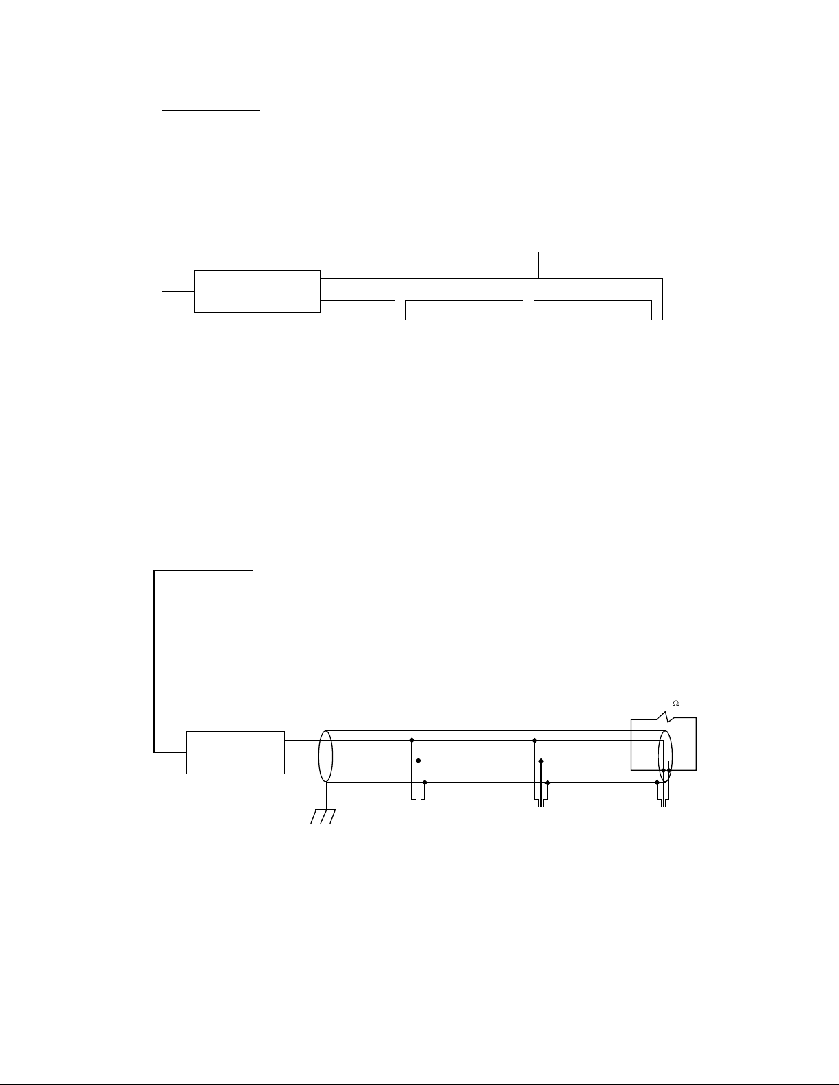
Communications Using Networking:The addressing capability of the M-6280A allows networking of multiple
M-6280A’s.Each capacitor bank control can be assigned an Address, Feeder Address or Substation Address
ranging from 1 to 65519. Selected commands may be broadcast to all controls on the network. Figures 3, 4
and 5 illustrate typical network configurations. Addresses 1-247 can be assigned to MODBUS and 1-65519
for DNP 3.0.
Application
Using CapTalk Communications Software, the operator has real-time, remote access to all functions of the
M-6280A. The protocols implement half-duplex, two-way communications. This allows all functions, which
would otherwise require the presence of an operator at the control, to be performed remotely. Communication
capabilities include:
• Interrogationandmodicationofsetpoints
• Broadcastofcommands
• Recognitionofalarmconditions,suchasvoltageextremes
• Unsolicitedexceptionreporting
• MulticastcapabilityusingUDP
Unit Identifier
A 2-row by 20-character alphanumeric sequence, set by the user, can be used for unit identification.
COM 1, RS-485, RS-232, (2Wire),
or Fiber Optic (ST or Vpin) Cable
USB Cable
Switched Capacitor Bank
Printer Computer Running CapTalk
®
S-6280
Communications Software
Beckwith
Digital
Capacitor
Control
Figure 2 Direct Connection
–13–
M-6280A Digital Capacitor Bank Control
Computer Running CapTalk
®
S-6280
Communications Software
ST Multi-mode or Vpin 62/125 or 200 Micron Optical Fiber
Connect to computer
Straight DB25
Connection to Computer
RS-232 COM Port
Dymec Model No. 5843
DTE = On
Repeat = Off
TX
RX
Figure 3 Fiber Optic Connection Loop
A
B
Model No. 485 LP9TB
B & B Electronics
RS-232/RS-485
120
Computer Running CapTalk
®
S-6280
Communications Software
Connect to computer
Straight DB9 Connection
to Computer RS-232
COM Port
Figure 4 RS‑485 Network Connection

–14–
M-6280A Digital Capacitor Bank Control
Network
CAT 5 Twisted Pair RJ-45
or
Fiber Optic Through
ST Connectors
Network Server
Computer Running CapTalk
®
S-6280
Communications Software
Hub
Figure 5 Optional Ethernet Network Connection
RS232 Link RS232 Link
Cellular Tower
RS232 Link
Figure 6 Cellular Modem Network
CellularModem withTCP/IPor UDPcapabilities using
standards-basedEDGE,GPRS,orCDMAtechnologies

–15–
M-6280A Digital Capacitor Bank Control
Environmental
Temperature:Controloperatesfrom–40°Cto+85°C.
NOTE: TheLCDdisplay’svisibletemperaturerangeis–20°Cto+70°C.
IEC60068-2-1Cold,–40°C
IEC60068-2-2DryHeat,+80°C
IEC60068-2-78DampHeat,+40°C@95%RH
IEC60068-2-30DampHeatCondensingcycle25°C,+55°C@95%RH
Transient Protection
HighVoltage
Allinputandoutputterminalswillwithstand2000Vacrmstochassisorinstrumentgroundforoneminutewith
aleakagecurrentnottoexceed25mA,forallterminalstoground.Inputandoutputcircuitsareelectrically
isolatedfromeachother,fromothercircuitsandfromground.
SurgeWithstand Capability
IEEEC37.90.1-2002 2,500VpkOscillatory
4,000VpkFastTransientBurst
IEEEC37.90.1-1989 2,500VpkOscillatory
5,000VpkFastTransient
NOTE: Disturbanceisappliedtodigitaldatacircuit(RS-485)portsthroughcapacitivecouplingclamp.
Radiated Immunity
IEC60255-22-3 10V/M
FastTransient/Burst Immunity
IEC60255-22-4
ClassA (4kV,2.5kHz,5kHz)
NOTE: Disturbanceisappliedtodigitaldatacircuit(RS-485)portsthroughcapacitivecouplingclamp.
Electrostatic Discharge
IEC60255-22-2 (8kV)Pointcontactdischarge
IEC60255-22-2 (15kV)Airdischarge
VoltageWithstand
DielectricWithstand
IEC60255-5 2,000Vacfor1minuteappliedtoeachindependentcircuittoearth
2,000Vacfor1minuteappliedbetweeneachindependentcircuit
ImpulseVoltage
IEC60255-5 5,000Vpk,+/-polarityappliedtoeachindependentcircuittoearth
5,000Vpk,+/-polarityappliedbetweeneachindependentcircuit
1.2µsby50µs,500ohmsimpedance,threesurgesat1every5seconds
Insulation Resistance
IEC60255-5 >100Megaohms
Surge Immunity
IEC60255-22-5 4,000Vpk,+/-polarityapplied,1.2µsby50µs,2ohms/12ohmsimpedance,vesurges
1every5seconds

–16–
M-6280A Digital Capacitor Bank Control
Voltage Interruptions Immunity
IEC60255-11
Mechanical Environment
IEC60255-21-1 VibrationResponseClass1 0.5g
VibrationEnduranceClass11g
IEC60255-21-2 ShockResponseClass1 5 g
ShockWithstandClass1 15g
BumpEnduranceClass1 10g
Physical
M-6280A
Size:9.18"widex15"highx3.22"deep(23.32cmx12.5cmx7.95cm)
Approximate Weight:6lbs,5oz(2.92kg)
Approximate Shipping Weight:10lbs,5oz(4.56kg)est.
Patent & Warranty
TheCapacitorControliscoveredbypendingU.S.Patents.
TheCapacitorControliscoveredbyatenyearwarrantyfromdateofshipment.
BluetoothistheRegisteredTrademarkofBluetoothSIG,Inc.
CapTalkistheRegisteredTrademarkofBeckwithElectricCo.,Inc.
MODBUSistheRegisteredTrademarkofGould,Inc.
Lexan®istheRegisteredTrademarkofGeneralElectricCo.
NEMAistheRegisteredTrademarkofNationalElectricalManufacturersAssociation
UListheRegisteredTrademarkofUnderwritersLaboratories,Inc.
WindowsistheRegisteredTrademarkofMicrosoftCorporation
Windows2000istheRegisteredTrademarkofMicrosoftCorporation
WindowsVistaistheRegisteredTrademarkofMicrosoftCorporation
WindowsXPistheRegisteredTrademarkofMicrosoftCorporation

–17–
M-6280A Digital Capacitor Bank Control
NEMA® 4X, Lexan
®
Meter Socket Mount Cabinet
Integrated Door
Hinge With Stainless
Steel Hinge Pin
External Grounding Stud
Cabinet Door Accomodates
Optional Power Supplies and
Communication Devices
Radio Antenna
Mounting Hole
Stainless Steel
Locking Clasps
Accept up to 3/8"
Hasp Locks
4, 5 or 6 Blade
Meter Socket
(4 Standard)
Factory Custom
Wiring Available
Radio Antenna
Mounting Hole
NEMA
®
4X, Lexan
®
Pole Mount Cabinet
Adjustable Direct Pole
Mounting Bracket
Integrated Door
Hinge With Stainless
Steel Hinge Pin
External Grounding Stud
Standard 5' Control Cable
(Optional cable lengths in five
foot increments up to 50 feet)
Adjustable Direct Pole
Mounting Bracket
Stainless Steel Locking
Clasps Accept up to 3/8"
Hasp Locks
4, 5 or 6 Blade
Meter Socket Plug
(4 Standard)
Factory Custom
Wiring Available
Cabinet Door Accomodates
Optional Power Supplies and
Communication Devices
Radio Antenna
Mounting Hole
Radio Antenna
Mounting Hole
Figure 7 M‑6280A Digital Capacitor Control NEMA 4X Lexan Cabinet, Multiple Common Connector,
Meter Socket Plug, and Meter Socket Mount

–18–
M-6280A Digital Capacitor Bank Control
15.00
[12.5]
Smart Flash SD Card
S O UR C E
V O LTAG E
INT
E X T
O FF
USB
RXTX
9.18
[23.32]
0.65
[0.17]
1.10
[2.8]
1.0
[2.54]
9.77
[24.82]
1.0
[2.54]
3.22
[8.18]
0.88
[2.24]
OK
OPEN ALARM
EXTERNAL
POWER METER
OUT
REMOTE/
AUTO
LOCAL/
MANUAL
CLOSE REMOTE/
AUTO
LOCAL/
MANUAL
CLOSE
OPEN
NEUTRAL
UNBALANCE
RSSI
COM
!
Made in U.S.A.
Digital Capacitor Bank Control
M-6280A
EXIT
WAKE
ENT
UTIL
SETP
COMM
MNTR
CNFG
BECKWITH
ELECTRIC CO. INC.
Figure 8 M‑6280A Control Outline Dimensions

–19–
M-6280A Digital Capacitor Bank Control
Neutral Current Input (POL)
Capacitor Bank Close Output
Neutral
1
2
3
4
5
6
7
8
9
10
11
12
TB2
1
2
3
4
5
6
7
8
9
10
11
12
13
14
15
TB1
16
1
2
3
J3
RS-485 A (+)
RS-485 B (-)
RS-485 Shield
Capacitor Bank Open Output
Not Used
Not Used
Not Used
Neutral Current Input (RTN)
Not Used
Switch Power Input
Line Voltage Input
Not Used
Load Current Input (RTN)
Load Current Input (POL)
Optional 5 A current input or 10 V
input from Line Post Sensor
Switch Status "C" Input
Switch Status "B" Input
Switch Status "A" Input
+12 V dc Wetting Supply
Alarm Output (NO)
Alarm Output Common
Alarm Output (NC)
Factory installed Jumper that is
required for Close/Open output
200 mA, 5 A CT, or Line Post
Current Sensor
Optional M-2980A
Cabinet Door Intrusion
Detection Switch
Open when cabinet door is open
Closed when cabinet door is closed
Not Used
- 12 V dc Backup Power
+ 12 V dc Backup Power
Figure 9 M‑6280A External Connections
Table of contents
Other BECKWITH ELECTRIC Control System manuals

Popular Control System manuals by other brands


Vaillant
Vaillant VR 940f installation instructions

Mitsubishi Electric
Mitsubishi Electric PAR-CT01MAA-SB Instruction book

BFT
BFT STOPPY MBB 219-500.C Instructions for installation, use and maintenance

Stagnoli
Stagnoli E24 manual

CYBELEC
CYBELEC CybTouch 12 user manual

Luraco
Luraco iFill 4 L0903A user manual