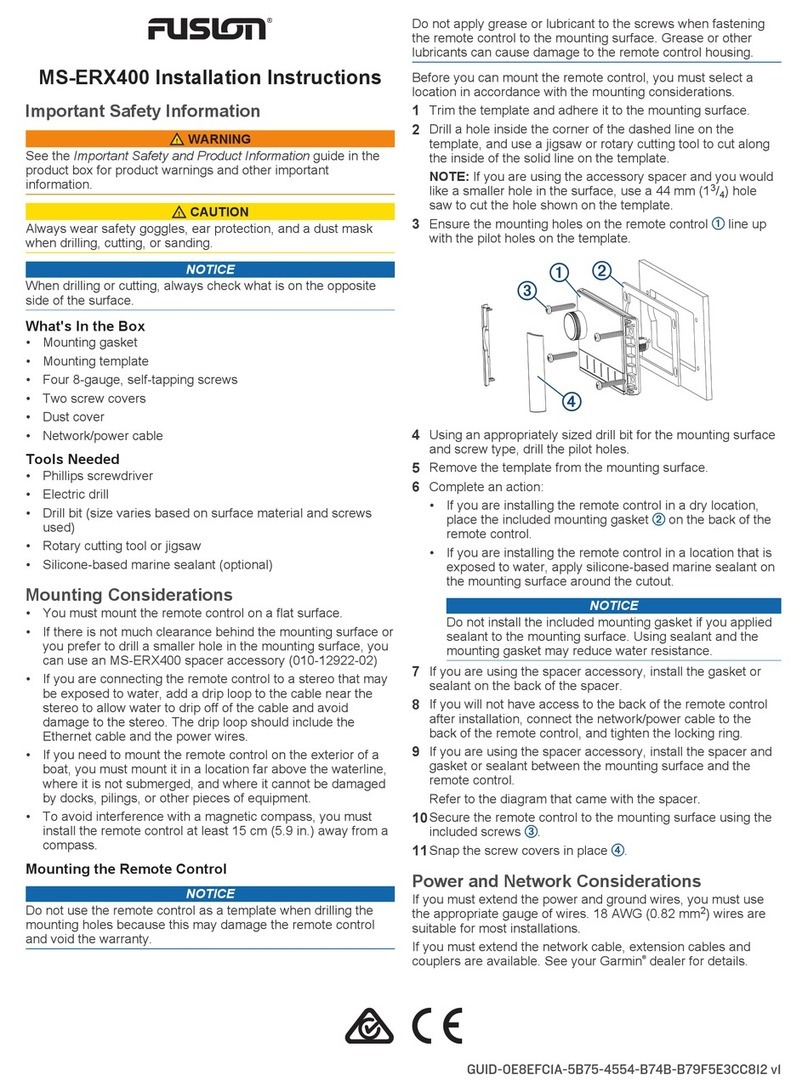
NewPwr C Series User manual

Double input, double output
-
+
1
2
-
+
3
4
5
6
7
8
24 V
24 V
Output1
Output2
Input1
Input2
Hazardous area Safe area
C Series
60 mA Digital Output
Isolated Safety Barrier
Website: http://www.anpe.cn
Service Tel: +86(25)-84459479
Address: New Power industrial Park, Luhe Economic Development Zone, Nanjing, China
Postcode: 211500
Nanjing New Power Electric Co., Ltd.
èIntroductions
By switch signals controlling, this isolated safety barrier
transfers the digital signals (wet contact) from a safe area
into current signals to a hazardous area, and drives field
device like intrinsically safe valves, audible alarms, etc.
The input and output are galvanically isolated from each
other. The apparatus was designed with various kinds of
advantages, for instance, high reliability and fast response,
etc. It can be interfaced with all kinds of device and DCS,
PLC and other systems.
èParameters
Explosive-proof grade: [Ex ia Ga] ⅡB
Loop Power supply: 20 V DC~30 V DC
Input (5, 6; 7, 8):
Input signal: Wet contact
Output (1, 2; 3, 4):
Max. Output voltage: 22 V
Min. Output voltage: 12 V
Output current: ≤ 60 mA
Electromagnetic compatibility: Accordance to IEC 61326-3-1
Dielectric strength (1 mA leakage current, 1 minute test time):
≥ 3000 V AC (intrinsically safe side / non-intrinsically safe side)
Insulation resistance: ≥ 100 MΩ (Input /Output)
Parameters certified by National Supervision and
Inspection Center for Explosion Protection and Safety of
Instrumentation (NEPSI):
Um: 250 V
Terminals 1, 2; Terminals 3, 4:
Uo: 25.2 V Io: 170 mA Po: 1.08 W Co: 0.82 μF Lo: 4 mH
Ambient conditions:
Operation temperature: −20 ℃ ~ +60 ℃
Relative humidity: 10% RH ~ 90% RH (40 ℃)
Atmosphere pressure: 80 kPa ~ 106 kPa
Storage temperature: −40 ℃ ~ +80 ℃
604040108400301
èSupport model type
èOutput equivalent circuit
èOutput characteristics diagram
èWiring diagram
NPEXB-C513L
Model number Single input,
single output
Double input,
double output
NPEXB-C5D13L
Min. 22 V
Max. 158 Ω
current limit 60 mA
60
12
22
Output voltage (V)
Output current (mA)
Safe area
5
6
2
1
+
-
24 V
Output Input
Hazardous area
Single input, single output
èDimension
Width × Height × Depth: 12.8 mm × 110 mm × 117 mm
èApplications
This apparatus is used for transmitting signals between
field devices and process control system. It can be used to
connect field equipment which is installed in potentially
explosive gas environment, and protect the intrinsically
safe equipment in a hazardous area by limiting current and
limiting voltage.
The apparatus can convert the wet contact signals from a
safe area into current signals to a hazardous area by
isolation, It is used to drive intrinsically safe apparatus. The
LED indicator on the front side can reflect the apparatus

C
B
A
Website: http://www.anpe.cn
Service Tel: +86(25)-84459479
Address: New Power industrial Park, Luhe Economic Development Zone, Nanjing, China
Postcode: 211500
Control unit
intrinsicall y
safe valves
C. Remove the safety barrier as arrow shows.
mAs far as possible to mount it vertically, In order to
dissipation the heat of the apparatus.
Vertically installation
èLight indication
mOUT1 and OUT2 (Dual channel) or OUT (Single channel):
Output status indicators. When the output loop
voltage is normal, the indicators turns to yellow.
èAttention
mIsolated Safety Barriers degree of protection is IP 20 and
must be protected from undesirable ambient conditions
(waterproofing, small foreign objects). It is suitable for
installation in the control room or high density field
cabinet, DIN 35 mm installation is convenient for
installation and displacement.
mThe devices were designed for use in pollution degree 2
and overvoltage category III as per IEC/EN 60664-1. If
used in areas with higher pollution degree, the devices
need to be protected accordingly.
mInstallation position shall not be affected by strong
mechanical vibration; impact and electromagnetic
induction from signal terminal and power supply, should
conformity with the requirements on electromagnetic
interference resistance of products in Class 3 industrial
field atmosphere stipulated in IEC 61000-4; the
atmosphere shall be free from gases that are corrosive to
metal and plastic components.
mThe apparatus must be installed, connected and adjusted
by qualified personnel in non-hazardous area according
with the instruction manual.
mThe operator must strictly comply with the relevant local
safety standards and guidelines.
è
Supplementary instructions
m
Our company reserves the right to change the product
information without prior notification to the user. If the
contents of the description are different from website or
sample, this description shall prevail.
output status.
èInstallation
mThe apparatus can be installed on the DIN 35 mm
standard rail which is corresponding to DIN IEC 60715.
The must be snapped onto the rail, and never slanted or
tipped to the side.
mInstallation and disassembly steps are shown in following
figures:
A. Snap metal lock onto mounting rail, then rotate the safety
barrier, as figure A, press down the safety barrier onto
mounting rail.
B. Pry the metal lock off the rail with screwdriver as arrow
shown, pull downward the springs, and rotate the safety
barrier.
1 0
9
8
7
6
5
2
1
4
3
1 0
9
8
7
6
5
2
1
4
3
1 0
9
8
7
6
5
2
1
4
3
1 0
9
8
7
6
5
2
1
4
3
1 0
9
8
7
6
5
2
1
4
3
1 0
9
8
7
6
5
2
1
4
3
604040108400301
This manual suits for next models
2
