BECKWITH ELECTRIC Syncrocloser M-5625 User manual

Syncrocloser®Digital
Synchronizing System
M‑5625
SYNCROCLOSER®
LINE
• Facilitatesstandardizationforgeneratorandsystemintertie
synccheckapplications
• Assuresafeandaccurateconnectionofagenerator
tothepowernetwork
• Providesaccuracyandindependentcontrols;noadditional
instrumentationisrequiredforeldsetting
• Breakerclosingtimesareeldprogrammable
• Localandremoteserialcommunications(MODBUSprotocol)
capabilityformonitoringandcontrolfunctions
Integrated Synchronizing System®for Generator
and Intertie Synchronizing

–2–
M‑5625 Digital Synchronizing System
Digital Synchronizing System
When the M-3410A relay is connected with Line-Line voltage input, the following functions are available
(refer to Figure 7 for wiring connections).
• Sync-checkwithPhaseAngle,∆V and ∆F with dead line/dead bus options (25)
• Reconnectenable(79)forintertieapplication
• Phaseundervoltage(27)detection
• Dual-setpoint,singleorthreephase,directionalpowermonitoringthatcanbeselectedasover
powerorunderpower(32)detection(requirescurrenttransformerinput)
• Negativesequenceovervoltage(47)detection
• Phaseovercurrent(51)detection(requirescurrenttransformerinput)
• Phaseovervoltage(59)detection
• VTfuse-lossdetectionandblocking(60FL)
• Four-stepover/underfrequency(81)detection
Ifaline-neutralisappliedtothesingleVTinputoftheM-3410AonlytheSynch-Check(25)Functionisviable.
The(51)Functionmayalsobeactiveforthisvoltagecongurationifcurrentinputisconnectedaswell(refer
toFigures5and6).
Standard Features
• SelectableAnti-MotoringandAnti-Pump
• AdjustableJogDurations,proportionaltoerror,forVoltageandSpeedControls
• TimeBetweenJogsadjustmentsbringthegeneratortoamatchedconditioninminimumtimeand
eliminateovershootandhuntingbyaccountingforinertialandcontrollags
• KickerPulsebringsphaseanglearoundthroughzeroifspeedismatchedbutsynchronismhas
notyetoccurred.Adjustablepulsedurationcompensatesforthesensitivityofthegovernor.
• OneAuto-syncoutput,twoSync-checkoutputs,oneself-testoutput,twoenableinputs,andtwo
control/status inputs
• Oscillographicrecording(COMTRADEleformat)
• Time-stampedsequenceofeventsrecordingfor32events
• MeteringofVoltage,DeltaVoltage,Frequency,DeltaFrequency,PhaseAngle,CurrentandSync
Scopeindication
• OneRS-232port(COM1)onfrontandoneRS-232or485port(COM2)onrear
• M-3810AIPScom®For WindowsTMCommunicationsSoftware
• MODBUSprotocol
• Supportsboth50and60Hzapplications
• Accepts1Aor5AratedCTinputs
• ContinuousSelf-Diagnostics
Optional Features
• M-3801DIPSplot®PLUS OscillographAnalysisSoftware
• HorizontalandVerticalpanelmountversionsavailable
• Standard19"RackMountAvailable

–3–
M‑5625 Digital Synchronizing System
Valuesinparenthesesapplyto1ACTsecondaryrating.
SYNCHRONIZING SYSTEM FUNCTIONS
Device Setpoint
Number Function Ranges Increment Accuracy
Sync Check
PhaseAngleWindow 0°to90° 1° 1°
UpperVoltageLimit 100.0to120.0%* 0.1% 0.5 V or 0.5%
LowerVoltageLimit 70.0to100.0%* 0.1% 0.5 V or 0.5%
DeltaVoltageLimit 1.0to50.0%* 0.1% 0.5 V
DeltaFrequencyLimit 0.001to0.500Hz 0.001Hz 0.001Hzor5%
SyncCheckTimeDelay 1to8160Cycles 1Cycle
DeadVoltageLimit 0.0to50.0%* 0.1% 0.5 V or 0.5%
DeadTimeDelay 1to8160Cycles 1Cycle 2Cycles
* Of nominal voltage.
Sync Check may be operated as a stand‑alone function or supervised by 79 (reconnect).Various combinations
of input supervised hot/dead closing schemes may be selected.
Phase Undervoltage
Pickup#1,#2 4to100%* 0.1% 0.5 V or 0.5%
TimeDelay#1,#2 1to8160Cycles 1 Cycle 2 Cycles**
* Of nominal voltage.
** When DFT is selected, the time delay accuracy is 2 cycles.When RMS magnitude is selected, an
additional time delay from 0 to +20 cycles may occur.
Directional Power
Pickup#1,#2 –3.00to+3.00PU 0.01 PU 0.02 PUor 2%*
TimeDelay#1,#2 1to8160Cycles 1 Cycle 2Cycles
The per‑unit pickup is based on nominalVT secondary voltage and nominal CT secondary current settings
for currents less than 14 A (2.8 A).This function can be selected as overpower or underpower in the forward
direction (positive setting) or reverse direction (negative setting).This function can also be selected for single
phase detection for line‑to‑ground VT.
Minimum sensitivity of 100 mA for 5 A CT (real component of current).
* Accuracy applies for a nominal current range of 2.5 A to 6 A (5 A CT) or 0.5 A to 1.5 A (1 A CT).
Negative Sequence Overvoltage
Pickup#1,#2 4to100%* 0.1% 0.5 V or 0.5%
TimeDelay#1,#2 1to8160Cycles 1 Cycle 2Cycles
* Of nominal voltage.
Inverse Time Overcurrent
Pickup 0.50to12.00A 0.01A 0.1 A or 3%
(0.10 to 2.40 A) (0.02 A or 3%)
CharacteristicCurve DeniteTime/Inverse/VeryInverse/ExtremelyInverse/IECCurves
TimeDial 0.5to11.0 0.1 3Cyclesor10%
0.05to1.10(IECcurves) 0.01
25
27
32
51
47

–4–
M‑5625 Digital Synchronizing System
SYNCHRONIZING SYSTEM FUNCTIONS (cont.)
Device Setpoint
Number Function Ranges Increment Accuracy
Phase Overvoltage
Pickup#1,#2 100to150%* 0.1% 0.5 V or 0.5%
TimeDelay#1,#2 1to8160Cycles 1 Cycle 2 Cycles**
* Of nominal voltage.
** When DFT is selected, the time delay accuracy is 2 cycles.When RMS magnitude is selected, an
additional time delay from 0 to +20 cycles may occur.
VT Fuse‑Loss Detection
AVT fuse-loss condition is detected by using the positive and negative sequence components
of the voltages and currents. VT fuse-loss output can be initiated from internally generated
logic or from input contacts.
TimeDelay 1to8160Cycles 1Cycle 2Cycles
Reconnect Enable Time Delay
TimeDelay 2to65,500Cycles 1 Cycle 2 Cycles
Reconnect timer starts when all outputs designated as trip outputs reset.
Over/UnderFrequency
Pickup#1,#2,#3,#4 50.00to67.00Hz 0.01Hz 0.03Hz
(40.00to57.00Hz*)
TimeDelay#1,#2,#3,#4 2to65,500Cycles 1Cycle 2Cyclesor0.01%
*This range applies to 50 Hz nominal frequency models.
The pickup accuracy applies to 60 Hz models at a range of 57 to 63 Hz, and to 50 Hz models at a range of 47
to 53 Hz.The accuracy is 0.15 Hz for a range of 52 to 57 Hz, and 63 to 67 Hz (for 60 Hz nominal) and 42 to
47 Hz and 53 to 57 Hz (for 50 Hz nominal).
Controls
UpperVoltageLimit 110to140Vac — ±1.5%offullscale
(either input)
LowerVoltageLimit 90to120Vac — ±1.5%offullscale
(either input)
DeltaVoltageLimit 1to5Vac(1) — ±5%offullscale
DeltaFrequencyLimit 0.05to0.5Hz(2) — ±3%offullscale
(1) Multiple times of this range (2 times to 10 times) are available.
(2) An additional range of 0.005 to 0.05 Hz is available.
79
60
FL
59
81

–5–
M‑5625 Digital Synchronizing System
SYNCHRONIZING SYSTEM FUNCTIONS (cont.)
Device Setpoint
Number Function Ranges Increment Accuracy
Controls (cont.)
SpeedControl
Speedmatchingrange
ofoperation 30to85Hz — —
TimeBetweenJogs 2to30seconds(3) — ±20%ofsetting
JogDuration (4) — ±20%ofsetting
KickerPulseRate(5) — ±20%ofsetting
KickerPulseDuration 0.1to1.5seconds — ±20%ofsetting
VoltageControl
Voltagematchingrange
ofoperation 30to200Vac — —
TimeBetweenJogs 1to15seconds(6) — ±20%ofsetting
JogDuration (7) — ±20%ofsetting
(3) A 1 to 15 second range is available.
(4) Proportional to error. Proportional Jog Duration is 1 to 10 seconds per Hz of frequency mismatch, linear
for rF (delta frequency) of 0.015 to 1.5 Hz of mismatch.
(5) One pulse per 6 to 120 seconds.A generator raise speed jog is produced in the time set on the Kicker
Pulse Duration Dial if the speed matcher does not operate.
(6) A 2 to 30 second range is available.
(7) Proportional to error. Proportional Jog Duration is 0.1 to 1.0 second per volt of mismatch, linear for rV
(delta voltage) of 1 to 20V of mismatch.
Nominal Settings
NominalVoltage 50to500V* 1V —
NominalCurrent 0.50to6.00A 0.01A —
VTCongurationLine-Line (For25Function)
Seal-inDelay 2to8160Cycles 1Cycle 1Cycleor1%
* Maximum measured range for (25) function settings is < 600 V.

–6–
M‑5625 Digital Synchronizing System
Description
The M-5625 Syncrocloser Digital Synchronizing
Systemissuitablefortheautomaticsynchronizing
ofageneratortotheelectricpowernetwork.The
systemprovidesspeedandvoltage“jogs”tobring
a generator to proper conditions of matching
voltage and frequency, prior to safely and
accuratelyclosingabreakerintoabusenergized
byanelectricpowernetwork.
TheDigitalSynchronizingSystemisintendedfor
three general classes of application:
• Initialconnectionofageneratortoapower
networkasshowninFigure1
GEN
52G
POWER NETWORK
BUS VT
GEN/LINE VT
CLOSE
AVR
GV
90R
90L
15R
15L
DIGITAL
SYNCHRONIZING SYSTEM
Figure 1 Automatic Synchronizing of a Generator to a Power Network
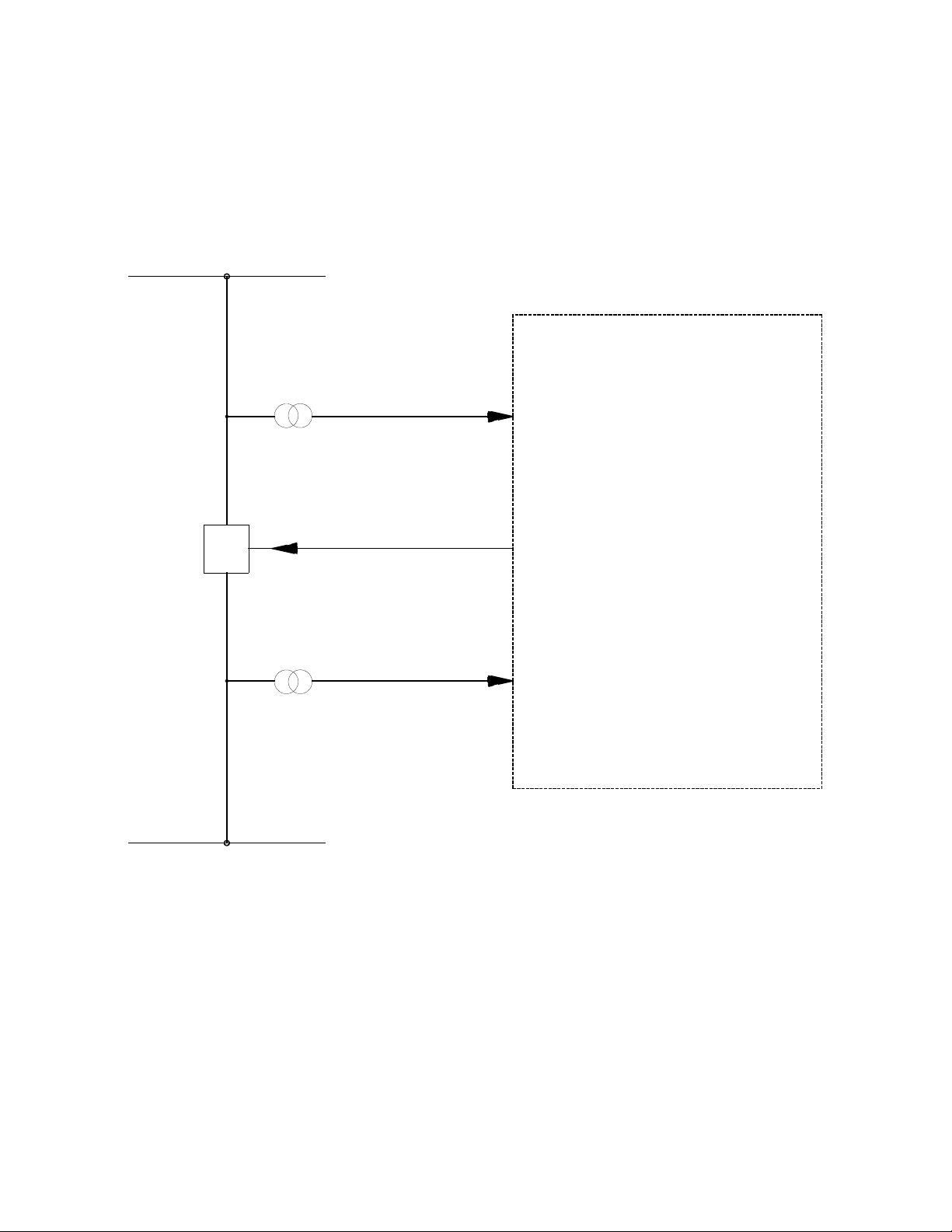
• Closure of a network breaker where
there is a possibility of a split of the
systemintotwoisolatednetworkshaving
different frequencies
• Breakerclosureapplicationswithastatic
phase angle (see Figure 2 Automatic
Synchronizing for Synchronous and
AsynchronouslinesandBusbars)
The system can also be used for manual
synchronizingapplication.AtypicalControlWiring
Diagram of Generator Synchronizing System is
illustrated in Figure 3.
–7–
M‑5625 Digital Synchronizing System
52
BUS/LINE 1
DIGITAL
SYNCHRONIZING SYSTEM
BUS VT
GEN/LINE VT
CLOSE
BUS/LINE 2
= BUS/LINE 2 VOLTAGE
= BUS/LINE 1 VOLTAGE
= SYNCHRONIZING CLOSE COMMAND
= CIRCUIT BREAKER
GEN/LINE VT
CLOSE
BUS VT
52
Figure 2 Automatic Synchronizing for Synchronous and Asynchronous Line and Busbars

–8–
M‑5625 Digital Synchronizing System
SYNC
(-)
CLOSE COIL
NOTES:
25A
52b
(BLACK CLOSE)
AUTO
25A
MANUAL
25-2
CIRCUIT BREAKER
90R
GENERATOR
= AUTOMATIC SYNCHRONIZER CLOSE COMMAND
25-1 = SYNC CHECK RELAY CLOSE 1 COMMAND
90L
25-2 = SYNC CHECK RELAY CLOSE 2 COMMAND (DEAD CLOSE)
15R
90L
90R
= RAISE SPEED COMMAND
= LOWER VOLTAGE COMMAND
= RAISE VOLTAGE COMMAND
15L = LOWER SPEED COMMAND
ENABLE DEAD CLOSE
(ENABLE BLACK CLOSE)
BLACK START PATH SYNC PATH
SYNCHRONIZING SYSTEM
25-1
15R
15L
TO EXCITATION SYSTEM
TO GOVERNOR
(+)
= CIRCUIT BREAKER STATUS CONTACT52b
(AUTOMATIC VOLTAGE REGULATOR)
(TURBINE REGULATOR)
DEAD CLOSE
Figure 3 Typical Control Wiring Diagram of Generator Synchronizing System

–9–
M‑5625 Digital Synchronizing System
Minimum Frequency Difference
TheguaranteedminimumfrequencydifferenceforAuto-Syncoperationis0.0005Hz.However,typicalunits
consistentlyoperatewithfrequencydifferenceof0.0001Hz.
Zero Phase Prediction
Figure4illustratestheaverageclosingphaseerrorasafunctionoffrequencydifferencefor80ms,100ms,
200ms,400msand800msbreakerclosingtimes.Thisdatawastakenunderlabconditionswithaconstant
frequency difference.
1.5
0.2
0.4
0.6
0.8
1.0
.01 0.5
0.4
0.3
0.1
.05
0
FREQUENCY DIFFERENCE IN HERTZ
AVERAGE CLOSING PHASE ERROR IN DEGREES
800 ms
400 ms
200 ms
100 ms
80 ms
Figure 4 Zero Phase Prediction
Anti‑Motoring
The Anti-Motoring feature prevents closing of the breaker when the generator frequency is slower than
theline/systemfrequency,thuspreventingmotoringpowerfromowingintothegenerator.Thisfunctionis
enabledbyaninternaltoggleswitch.Thedefaulttoggleswitchpositionis"OFF"(disabled).
Anti‑Pump
Thebreakerclose contactoftheautomaticsynchronizerwillcloseforapproximately0.5second.Power
supply to the automatic synchronizer must be removed for approximately 10 seconds before another
closureispossible,regardlessoftheotherinputs.AfrontpanelLED(M-0193BREADY)indicatesthatthe
automaticsynchronizerisactiveandreadytooperate,provideinputconditionsmeettheirrespectivelimits.
The automatic synchronizer can be ordered without the Anti-Pump Option. In this case, the automatic
synchronizerwillcloseonceoneachslipcyclewhenallinputconditionsarewithintheirlimitsandtheunit
isenabled.Theanti-pumpoptionmustbespeciedonorder.
Operator Window Option
TheOperatorWindowOptionallowsanoperatortoworkinconjunctionwiththeautomaticsynchronizer.The
operator’scontactmustbeclosedwithinavariabletimeandphaseangle“window”,otherwisetheautomatic
synchronizerwillblockclosingofthebreaker.Theunitwillthenautomaticallyresetforthenextattemptto
close.Theoperatorwindowoptionmustbespeciedonorder.

–10–
M‑5625 Digital Synchronizing System
Metering
The Digital Synchronizing System provides metering of voltages, currents, real power, reactive power,
power factor, frequency and positive sequence impedance.
Metering Accuracies are:
Voltage: 0.5 V or 0.5%, whichever is greater (Range 0 to 600 V)
Current: 5 A rating, 0.1 A or 3%, whichever is greater (Range 0 to 14 A)
1 A rating, 0.02 A or 3%, whichever is greater (Range 0 to 2.8 A)
Power: 0.02 PU or 2%, whichever is greater
Frequency: 0.03 Hz (from 57 to 63 Hz for 60 Hz models; from 47 to 53 Hz for 50 Hz models)
Sync Scope: The Sync Scope screen displays a phasor representation, the phase angle, delta voltage
and delta frequency of generator and incoming voltages.The display should not be used to
determine in phase conditions for manual synchronizing because of communications time
delay.
Oscillographic Recorder
The oscillographic recorder provides comprehensive data recording of all monitored waveforms, input
contacts and output contacts, storing up to 120 cycles of data. The total record length is configured for
one or two partitions. A programmable post trigger delay (5 to 95%) is incorporated to capture breaker
operation.The oscillograph is triggered either remotely using the serial interface, or designated status input
signals or M-5625 programmable output operations.Storage of oscillographic records is nonvolatile, and will
be retained even without power, as long as the on-board battery is healthy.
Oscillographic data can be downloaded using serial communication in Common Format ForTransient Data
Exchange (COMTRADE) format as specified by IEEE Standard C37.111-1999.
Sequence of Events
A total of 32 nonvolatile events can be stored.The recorded information includes the function(s) operated,
the function(s) picked up, input/output contact status and time stamp.The events can be retrieved through
the communications port. After the 32nd event is stored, additional events result in the oldest event being
dropped (FIFO).The information is time-stamped to 1 ms resolution.
Calculations
Current and Voltage Values: Uses discrete Fourier transform (DFT) algorithm on sampled (32 times per
cycle) voltage and current signals to extract fundamental frequency phasors for calculations. When set for
RMS measurement, uses a time domain algorithm to calculate the voltage magnitude.
Power Input
Nominal 120 V ac, 50/60 Hz, 100 to a maximum of 140V ac, 22 VA maximum burden at 120 V ac.
Other power input options are available for M-3410A only:
Nominal Range Burden
12/24 V dc 9 to 36 V dc <5 VA
48 V dc 36 to 75 V dc <5 VA
120 V ac/125 V dc 85 to 150 V ac/V dc <5 VA

–11–
M‑5625 Digital Synchronizing System
Sensing Inputs
2 Voltage Inputs: Gen/LineandBusvoltages,nominal120Vac,60Hz(Optional50Hzusercongurable).
Willwithstand145Vacmaximumcontinuousvoltage,200Vacfor1second.Voltagetransformerburden
less than 0.5 VA at 120 V ac.
3 Current Inputs: Rated current(IR) of 5.0 Aor 1.0 A, 60Hz (50 Hz usercongurable).Will withstand
2 IRcontinuous current and 30 IRfor2seconds.Currenttransformerburdenislessthan0.75VAat5Afor
5 A inputs, 0.3 A at 1 A for 1 A inputs.
Control/Status Inputs
• Thestatusinputs,INPUT1(breakerstatus52)andINPUT2(Auto-Syncclosecommand),canbe
usedtotriggertheoscillographrecorder.Thecontrolstatusinputsacceptonlydrycontactsand
areinternallywettedbytherelay’spowersupply.Aminimumcurrentof1.3mAisrequiredtoavoid
spurious triggering of the input.
• EnableAuto-Syncclose
• EnableGeneratorControlUnitforspeedandvoltagematching
• Breakerclosingtime:eldprogrammablefrom20to800ms
Output Contacts
Auto‑Sync Close Output:Outputwillcloseforapproximately0.5second.Normally-opendryoutputcontact
ratedtomakeandcarry20Aupto250Vdc,interrupt0.9A,120Vdcinductiveload;0.4A,250Vdc
inductive load.
Raise and Lower Voltage Jog Outputs, Raise and Lower Speed Jog Outputs:Normally-opendryoutput
contactratedtomakeandcarry20Aupto250Vdc,interrupt0.9A,120Vdcinductiveload;0.4A,250V
dc inductive load.
Sync Check Close Outputs:Twoprogrammableoutputrelays,eachwithacontactareratedasperANSI/
IEEEC37.90-1989fortripping:make30Afor0.2seconds.Availablehardwarecongurationsincludetwo
normallyopen(OptionB1),onenormallyopenandonenormallyclosed(OptionB2),ortwonormallyclosed
(OptionB3)contacts.Thecontactswillcarry8A,break6Aat120Vac,break0.1Aat125Vdc,inductive
break0.1A.Alsoprovidedisaself-testalarmoutputcontact(form'c')witharatingof8Aat120Vac,5A
at 30 V dc, 125 V dc 0.15 A resistive, 0.1 A inductive.
AnyoftheM-3410Aprotectivefunctionscanbeindividuallyprogrammedtoactivatethetwoprogrammable
outputs.Theusercancongurethetwoprogrammableoutputstoeitherenergizeorde-energizetoissue
anoutputcommand.
The outputs (excluding the self-test) can have two modes of operation, LATCHING and NORMAL.The
LATCHINGmoderequiresanoperatorinterventiontodeactivatetheoutputsaftertheconditionforoperation
hasbeenremoved.IntheNORMALmode,whentheconditionfortrippinghasbeenremoved,theoutput(s)
willdeactivateautomaticallyafterthecorrespondingseal-intimershaveexpired.
Status Output Contacts
rV Status Output:ClosedwhenrV(deltavoltage)iswithinlimits.Normally-opendryoutputcontactrated
0.5 A at 125 V dc resistive, 1 A at 120 V ac or 250 V dc across open contact.
rF Status Output:ClosedwhenrF(deltafrequency)iswithinlimits.Normally-opendryoutputcontact
rated 0.5 A at 125 V dc resistive, 1 A at 120V ac or 250 V dc across open contact.
Auto‑Sync Close Status Output:ClosedwhenAuto-Syncclosedcommandisissued.Normally-opendry
output contact rated 0.5 A at 125 V dc resistive, 1 A at 120V ac or 250 V dc across open contact.
Self‑Test Alarm Output:Form‘c’dryoutputcontactwithratingof8Aat120Vac,5Aat30Vdc,125Vdc
0.15 A resistive, 0.1 A inductive.
TheStatusOutputContactsarelightdutycontactsintendedprimarilyforstatusinterrogationbysupervisory
control.Theycanbeusedtoilluminatelocallampswithintheabovemaximumratings.

–12–
M‑5625 Digital Synchronizing System
Target/Status Indicators (LEDs)
• UPPERVOLTAGELIMITBUSOK
• UPPERVOLTAGELIMITGEN/LINEOK
• LOWERVOLTAGELIMITBUSOK
• LOWERVOLTAGELIMITGEN/LINEOK
• rV LIMITOK
• rF LIMITOK
• M-0193BREADY
• SENDINGRAISESPEED
• SENDINGLOWERSPEED
• SENDINGRAISEVOLTAGE
• SENDINGLOWERVOLTAGE
• BUSFREQUENCYHIGH
• GENERATORFREQUENCYHIGH
• PHASEUV27
• DIRECTIONALPOWER32
• VOLT.UNBALANCE47
• OVERCURRENT51
• PHASEOVERVOLTAGE
• 60FLFUSELOSS
• 81O/UFREQUENCY
• OSCTRIGGER (indicates that the oscillograph has been triggered)
• DIAGNOSTIC(providesindicationoftheerrorcodewhenashing)
• RELAYOK(revealspropercyclingoftheSyncCheckrelaymicroprocessor)
• OUTPUT1andOUTPUT2areusedtoindicatethestatusoftheSyncCheckoutputcontacts.
TheoutputLEDswillilluminatewhentheSyncCheckoutputcontactsareclosed.
LEDTestpushbuttonresetsthetargetLEDsoftheSyncCheckfunctioniftheconditionscausingtheoperation
havebeenremoved.HoldingtheTarget/OutputResetbuttondisplaysthepresentstatusoftheSyncCheck
function.
Communication
CommunicationsportsincludeafrontpanelRS-232portandarearportusercongurabletoRS-232or
RS-485.TheRS-232portsareconnectedphysicallywithaDB-9connectorandtheRS-485portutilizes
4-wireinterfacemountingscrewterminals.
M-3810AIPScom®ForWindowsTMCommunicationsSoftwareutilizingtheMODBUScommunicationsprotocol
inRTUmode,implementsserial,byte-orientedasynchronouscommunicationwiththeM-3410Aandprovides
the following functions:
• Interrogationandmodicationofsetpoints
• Time-stampedsequenceofeventsinformationforthe32mostrecentevents
• Real-timemeteringofallquantitiesmeasured
• Downloadingofrecordedoscillographicdata
• SyncCheckRelaySetup

–13–
M‑5625 Digital Synchronizing System
Tests and Standards
TheM-5625DigitalSynchronizingSystemconsistsoftheM-0193B,M-0194andtheM-3410Acomponents.
TheM-3410AmeetsorexceedsthefollowingTests&Standards,theM-0193BandtheM-0194havenot
beentestedtoalloftheTests&Standardslistedbelow.Pleasecontactthefactoryforacompletelistingof
applicableTests&Standardsforeachcomponent.
TheM-5625DigitalSynchronizingSystemcomplieswiththefollowingtypetestsandstandards:
Voltage Withstand
DielectricWithstand
IEC60255-5 3,500Vdcfor1minuteappliedtoeachindependentcircuittoearth
3,500Vdcfor1minuteappliedbetweeneachindependentcircuit
NOTE: 1,500Vdcfordcpowersupplyoptions(12,24,48Vdc).
ImpulseVoltage
Power Supply InputVoltages, 120 V ac/125 V dc:
IEC60255-5 5,000Vpk,+/-polarityappliedtoeachindependentcircuittoearth
5,000Vpk,+/-polarityappliedbetweenindependentcircuits
1.2 µs by 50 µs,500ohmsimpedance,threesurgesatevery5secondinterval
Power Supply InputVoltages, 12, 24, 48 V dc:
IEC60255-5 3,000Vpk,+/-polarityappliedtoeachindependentcircuittoearth
3,000Vpk,+/-polarityappliedbetweenindependentcircuits
1.2 µs by 50 µs,500ohmsimpedance,threesurgesatevery5secondinterval
Insulation Resistance
IEC60255-5 >100Megaohms
Electrical Environment
Electrostatic DischargeTest
EN60255-22-2 Class4(8KV)-Pointcontactdischarge
Class4(15KV)-Airdischarge
FastTransient DisturbanceTest
EN60255-22-4ClassA(4KV,2.5KHZ)
SurgeWithstand Capability
ANSI/IEEE 2,500VpkOscillatoryeachindependentcircuittoearth
C37.90.1 2,500VpkOscillatorybetweeneachindependentcircuit
2002 4,000VpkFastTransientburstappliedtoeachindependentcircuittoearth
4,000VpkFastTransientburstappliedbetweeneachindependentcircuit
5,000VpkFastTransienteachindependentcircuittoearth
5,000VpkFastTransientbetweeneachindependentcircuit
NOTE: Thesignalisappliedtothedigitaldatacircuits(RS-232,RS-485)communicationportsthrough
capacitivecouplingclamp.

–14–
M‑5625 Digital Synchronizing System
Radiated Susceptibility
ANSI/IEEE 80-1000Mhz@35V/m(withKeyingtest)
C37.90.2
2004
Output Contacts
ANSI/IEEE Make30Afor0.2seconds,offfor15secondsfor2,000operations
C37.90.0 Section6.7.1,TrippingOutputPerformanceRequirements
Atmospheric Environment
Temperature
IEC60068-2-1 Cold,–20°C
IEC60068-2-2 DryHeat,+70°C
IEC60068-2-78DampHeat,+40°C@93%RH
Mechanical Environment
Vibration
IEC60255-21-1 VibrationresponseClass1,0.5g
VibrationenduranceClass1,1.0g
IEC60255-21-2 ShockResponseClass1,5.0g
ShockWithstandClass1,15.0g
BumpEnduranceClass1,10.0g
Compliance
cULusListedper508 – IndustrialControlEquipmentcertiedforCanadaCAN/CSAC22.2NO.14-M91
cULusListedComponentper508ATableSA1.1IndustrialControlPanels
Physical
19" Rack Mount
Size: 10.50"highx19.0"widex14.00"deep(26.7cmx48.26cmx35.56cm)
Approximate Weight: 36lbs,(16.33kg)
Approximate Shipping Weight: 53lbs,(24.04kg)
Vertical Panel Mount
Size: 19.00"highx10.50"widex14.00"deep(48.26cmx26.7cmx35.56cm)
Approximate Weight: 36lbs,(16.33kg)
Approximate Shipping Weight: 53lbs,(24.04kg)
Patent & Warranty
TheM-5625SyncrocloserDigitalSynchronizingSystemiscoveredbyU.S.Patent3,491,248.
The M-5625 Syncrocloser Digital Synchronizing System is covered by a ve year warranty from
dateofshipment.
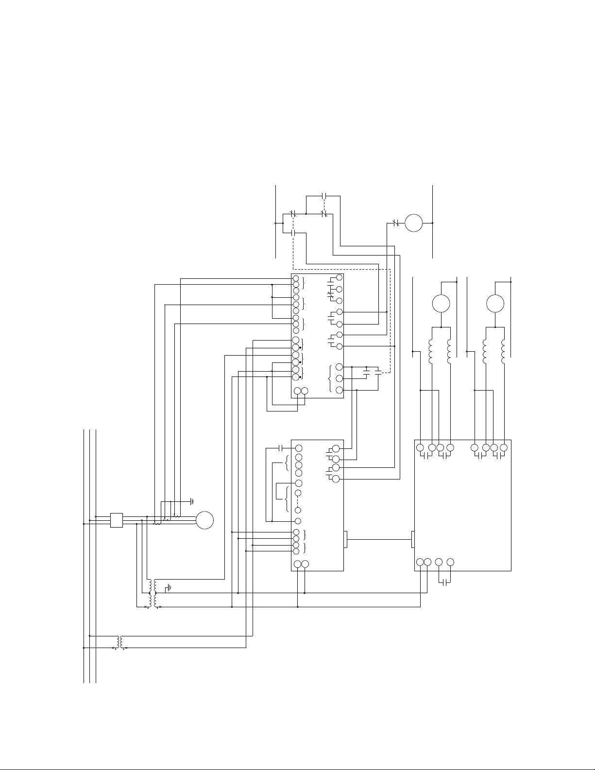
External Connections
M-5625externalconnectionpointsareillustratedinFigure5,ExternalConnections.
–15–
M‑5625 Digital Synchronizing System
Figure 5 External Connections, Two Phase-Phase VTs
52G
A
C
B
28
AUTO SYNC
ENABLE
(OPEN TO
ENABLE)
PROGRAM BREAKER TIME
NOTE 1 NOTE 1
BUS VT
120VAC
2
27
4
1
ENABLE
(OPEN TO ENABLE)
INTERCONNECT
CABLE
5A
3-CTs
RUNNING BUS
NOTE 3
NOTE 2
NOTE 2
CC = CLOSE COIL
= GENERATOR CIRCUIT BREAKER52G = GENERATOR BREAKER STATUS CONTACTS52a
= RAISE SPEED COMMAND15R = LOWER SPEED COMMAND15L = RAISE VOLTAGE COMMAND90R = LOWER VOLTAGE COMMAND90L = GOVERNOR65 = VOLTAGE REGULATING DEVICE90
= SYNC-CHECK RELAY CLOSE 1 COMMAND
= AUTOMATIC SYNCHRONIZER CLOSE COMMAND25A
25-1 = SYNC-CHECK RELAY CLOSE 2 COMMAND (DEAD CLOSE)25-2
90
R
90
L
15
R
15
L
OUT 1
SYNC-CHECK RELAY
VOLTAGE AND SPEED MATCHER
OUT 2
AUTOMATIC
SYNCHRONIZER
1A 5A 1A 5A 1A 5ACOM COM COM
ICB
IIA
(25-1)
OUT 1 (25-2)
OUT 2
IN2 RTN
IN1
INPUTS ONLY
DRY CONTACT
52a
DEAD CLOSE
OUT 3
SELF-TEST
5 6 7
65
R
SPEED MATCHING SUPPLY (+)
L
SPEED MATCHING SUPPLY (-)
VOLTAGE MATCHING SUPPLY (-)
L
R
90
VOLTAGE MATCHING SUPPLY (+)
H N N H
H
N
H
N
VSYNC
GENERATOR BREAKER SUPPLY (+)
GENERATOR BREAKER SUPPLY (-)
52G
CC
AUTO MANUAL
SYNC SYNC
52b
SYNC
DEAD CLOSE
+
-
BUS
VT GEN/LINE
VT
GEN VT
120VAC
52b = GENERATOR BREAKER STATUS CONTACTS
25A 25A
NOTES:
FOR INSTRUCTIONS REGARDING BREAKER TIME PROGRAMMING.
1. CONNECT AS REQUIRED. REFER TO THE M-0193B INSTRUCTION BOOK
2. CONNECT 27(H) & 26(N) OF M-0193B AND 1(H) & 2(N) OF M-0194 TO A POWER
SUPPLY SOURCE IF AVAILABLE.
3. CONNECT 28(+) & 27(-) OF M-3410A TO POWER SUPPLY SOURCE IF AVAILABLE.
4. THE CURRENT INPUTS ARE FOR METERING AND OSCILLOGRAPHIC RECORDING
PURPOSE ONLY IF NEEDED AND ARE NOT REQUIRED FOR (25) FUNCTION.
5. ADDITIONAL OUTPUT 2 IF NEEDED FOR M-0193B-MOD 410, 10A at 24 V dc CONTACT RATING.
GEN
E
H
F
G
D
A
B
C
HGB
A
27
26 57
123 4 19
18
17
16 20
NOTE 4
4343
24 25 26
28
27
910 11 12 13 14
2322
2120191817
16
15
NOTE 5
V
AB
V
BC
–16–
M‑5625 Digital Synchronizing System
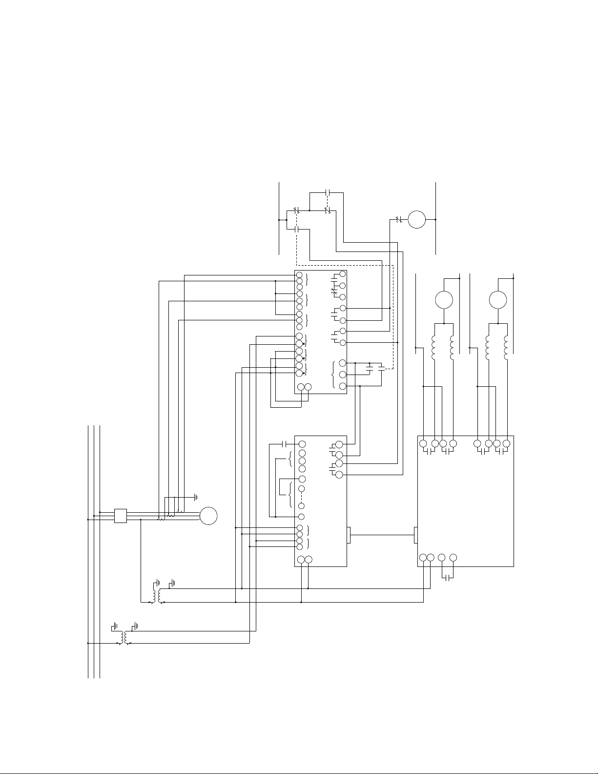
Figure 6 External Connections, Single Phase-Ground VTs
52G
A
C
B
28
AUTO SYNC
ENABLE
(OPEN TO
ENABLE)
PROGRAM BREAKER TIME
NOTE 1 NOTE 1
BUS VT
120VAC
2
27
4
1
ENABLE
(OPEN TO ENABLE)
INTERCONNECT
CABLE
5A
3-CTs
RUNNING BUS
NOTE 3
NOTE 2
NOTE 2
CC = CLOSE COIL
= GENERATOR CIRCUIT BREAKER52G = GENERATOR BREAKER STATUS CONTACTS52a
= RAISE SPEED COMMAND15R = LOWER SPEED COMMAND15L = RAISE VOLTAGE COMMAND90R = LOWER VOLTAGE COMMAND90L = GOVERNOR65 = VOLTAGE REGULATING DEVICE90
= SYNC-CHECK RELAY CLOSE 1 COMMAND
= AUTOMATIC SYNCHRONIZER CLOSE COMMAND25A
25-1 = SYNC-CHECK RELAY CLOSE 2 COMMAND (DEAD CLOSE)25-2
90R
90L
15R
15L
OUT 1
SYNC-CHECK RELAY
VOLTAGE AND SPEED MATCHER
OUT 2
AUTOMATIC
SYNCHRONIZER
1A 5A 1A 5A 1A 5ACOM COM COM
ICB
IIA
(25-1)
OUT 1 (25-2)
OUT 2
IN2 RTN
IN1
INPUTS ONLY
DRY CONTACT
52a
DEAD CLOSE
OUT 3
SELF-TEST
5 6 7
65
R
SPEED MATCHING SUPPLY (+)
L
SPEED MATCHING SUPPLY (-)
VOLTAGE MATCHING SUPPLY (-)
L
R
90
VOLTAGE MATCHING SUPPLY (+)
H N N H
H
N
H
N
VSYNC
GENERATOR BREAKER SUPPLY (+)
GENERATOR BREAKER SUPPLY (-)
52G
CC
AUTO MANUAL
SYNC SYNC
52b
SYNC
DEAD CLOSE
+
-
BUS
VT GEN/LINE
VT
GEN VT
120VAC
52b = GENERATOR BREAKER STATUS CONTACTS
25A 25A
NOTES:
FOR INSTRUCTIONS REGARDING BREAKER TIME PROGRAMMING.
1. CONNECT AS REQUIRED. REFER TO THE M-0193B INSTRUCTION BOOK
2. CONNECT 27(H) & 26(N) OF M-0193B AND 1(H) & 2(N) OF M-0194 TO A POWER
SUPPLY SOURCE IF AVAILABLE.
3. CONNECT 28(+) & 27(-) OF M-3410A TO POWER SUPPLY SOURCE IF AVAILABLE.
4. THE CURRENT INPUTS ARE FOR METERING AND OSCILLOGRAPHIC RECORDING
PURPOSE ONLY IF NEEDED AND ARE NOT REQUIRED FOR (25) FUNCTION.
5. ADDITIONAL OUTPUT 2 IF NEEDED FOR M-0193B-MOD 410, 10A at 24 V dc CONTACT RATING.
6. VOLTAGE INPUT TO 11 & 12 IS REQUIRED FOR DEAD V1 OR DEAD V2 FUNCTION.
GEN
E
H
F
G
D
A
B
C
HGB
A
27
26 57
123 4 19
18
17
16 20
NOTE 4
4343
24 25 26
28
27
910 11 12 13 14
2322
2120191817
16
15
NOTE 5
V
AB
V
BC
NOTE 6

–17–
M‑5625 Digital Synchronizing System
52G
A
C
B
28
AUTO SYNC
ENABLE
(OPEN TO
ENABLE)
PROGRAM BREAKER TIME
NOTE 1 NOTE 1
BUS VT
120VAC
2
27
4
1
ENABLE
(OPEN TO ENABLE)
INTERCONNECT
CABLE
5A
3-CTs
RUNNING BUS
NOTE 3
NOTE 2
NOTE 2
CC = CLOSE COIL
= GENERATOR CIRCUIT BREAKER52G = GENERATOR BREAKER STATUS CONTACTS52a
= RAISE SPEED COMMAND15R = LOWER SPEED COMMAND15L = RAISE VOLTAGE COMMAND90R = LOWER VOLTAGE COMMAND90L = GOVERNOR65 = VOLTAGE REGULATING DEVICE90
= SYNC-CHECK RELAY CLOSE 1 COMMAND
= AUTOMATIC SYNCHRONIZER CLOSE COMMAND25A
25-1 = SYNC-CHECK RELAY CLOSE 2 COMMAND (DEAD CLOSE)25-2
90R
90L
15R
15L
OUT 1
SYNC-CHECK RELAY
VOLTAGE AND SPEED MATCHER
OUT 2
AUTOMATIC
SYNCHRONIZER
1A 5A 1A 5A 1A 5ACOM COM COM
ICB
IIA
(25-1)
OUT 1 (25-2)
OUT 2
IN2 RTN
IN1
INPUTS ONLY
DRY CONTACT
52a
DEAD CLOSE
OUT 3
SELF-TEST
5 6 7
65
R
SPEED MATCHING SUPPLY (+)
L
SPEED MATCHING SUPPLY (-)
VOLTAGE MATCHING SUPPLY (-)
L
R
90
VOLTAGE MATCHING SUPPLY (+)
H N N H
H
N
H
N
VSYNC
GENERATOR BREAKER SUPPLY (+)
GENERATOR BREAKER SUPPLY (-)
52G
CC
AUTO MANUAL
SYNC SYNC
52b
SYNC
DEAD CLOSE
+
-
BUS
VT GEN/LINE
VT
GEN VT
120VAC
52b = GENERATOR BREAKER STATUS CONTACTS
25A 25A
NOTES:
FOR INSTRUCTIONS REGARDING BREAKER TIME PROGRAMMING.
1. CONNECT AS REQUIRED. REFER TO THE M-0193B INSTRUCTION BOOK
2. CONNECT 27(H) & 26(N) OF M-0193B AND 1(H) & 2(N) OF M-0194 TO A POWER
SUPPLY SOURCE IF AVAILABLE.
3. CONNECT 28(+) & 27(-) OF M-3410A TO POWER SUPPLY SOURCE IF AVAILABLE.
4. THE CURRENT INPUTS ARE FOR METERING AND OSCILLOGRAPHIC RECORDING
PURPOSE ONLY IF NEEDED AND ARE NOT REQUIRED FOR (25) FUNCTION.
5. ADDITIONAL OUTPUT 2 IF NEEDED FOR M-0193B-MOD 410, 10A at 24 V dc CONTACT RATING.
6. VOLTAGE INPUT TO 11 & 12 IS REQUIRED FOR DEAD V1 OR DEAD V2 FUNCTION.
GEN
E
H
F
G
D
A
B
C
HGB
A
27
26 57
123 4 19
18
17
16 20
NOTE 4
4343
24 25 26
28
27
910 11 12 13 14 2322
2120191817
16
15
NOTE 5 V
AB
V
BC
NOTE 6
Figure 7 External Connections, Single Phase-Phase VTs

800-5625-SP-02MC1 01/13
© 2005 Beckwith Electric Co. All Rights Reserved.
Printed in USA
This manual suits for next models
1
Table of contents
Other BECKWITH ELECTRIC Control System manuals

Popular Control System manuals by other brands

Exhausto
Exhausto VEX320CX installation instructions

CYBELEC
CYBELEC CybTouch 12 user manual

Mitsubishi Electric
Mitsubishi Electric TC-24A installation manual

Basler
Basler DECS-200 instruction manual

Rittal
Rittal DET-AC III Slave Mounting, installation and operating instructions

Scanreco
Scanreco G6 Service manual


Fly Sky
Fly Sky FS-GT2 instruction manual

Fly Sky
Fly Sky FMS-G7 quick start guide

Spraying Systems
Spraying Systems TeeJet TECHNOLOGIES BoomPilot installation manual

Fly Sky
Fly Sky FS-G4P-BS user manual

Astral Pool
Astral Pool Viron Connect 10 Installation and operating instructions

Aqua Control
Aqua Control C4115 manual