BECKWITH ELECTRIC M-0329B User manual

Instruction Book
M-0329B LTC
Backup Control

• Prevents a defective LTC tapchanger control from running the voltage
outside the upper or lower limits
• Prevents the line drop compensator from raising the voltage too high
under full or overload conditions
• Fully transient protected and operates within ±1% voltage accuracy over
a temperature range of –40° to +80° C
• Includes First Customer Protection
LTC Backup Control
M-0329B
CONTROLS

–2–
M-0329B Backup Control
The M-0329B LTC Backup Control provides the extra protection that can save your customers from the hazards
and inconvenience of excessively high or low voltage. Defective LTC tapchanger controls can cause either too
high or too low a voltage along the line, possibly damaging customers' motors, computers or televisions. Even
when the control is operating properly, customers close to the transformer may receive dangerously high voltage
as the line drop compensator attempts to maintain a constant voltage under heavy load at a central point on the
distribution line. The Beckwith Electric M-0329B LTC Backup Control can be installed as a solution to both of
these problems.
The LTC Backup Control will prevent a defective LTC tapchanger control from running the voltage outside the
upper and lower voltage limits and, in addition, will prevent the line drop compensator from raising the voltage too
high under full load or overload conditions. Setting the voltage bands on the M-0329B slightly wider than the
transformer control limits will assure that a failed control will not result in a runaway LTC transformer. Under full
or overload conditions, the control automatically takes over as an upper voltage limit control, not affected by load
current, to prevent damage to equipment close to the transformer. While the Block Raise contact prevents a raise
operation, a Lower contact forces the tapchanger down if the primary voltage should subsequently rise.
Features
Block Raise and Block Lower voltage levels are set by accurately calibrated BANDCENTER and BANDWITH
controls, similar to those found on LTC transformer controls.
BLOCK RAISE/LOWER and LOWER LEDs indicate backup control status.
Block Raise, Block Lower, Lower and Alarm contacts provide outputs to drive external components.
Inputs
Power: 90 to 140 V ac, 50/60 Hz, 2 W at 120 V ac
Voltage: Less than 0.2 VA burden at 120 V ac input
Front Panel Controls
BANDWITH VOLTS: An accurately calibrated dial adjusts the bandwidth between Block Raise and Block Lower
from 6 V to 24 V for 120 V ac.
BANDCENTER VOLTS: An accurately calibrated dial adjusts the Bandcenter from 100 V rms to 140 V rms
which allows the M-0329B to operate with most transformer controls.
TIME DELAY SECONDS: Adjustable from 1 to 30 seconds. If voltage remains above the maximum (Block
Raise) voltage by the selected amount for longer than the time set on the timer delay control, the M-0329B will
initiate a tapchanger operation to lower the voltage.
Selectable Deadband: The deadband is the voltage range above the Block Raise Level where no tap changer
operation takes place. In the M-0329B, it is selectable as 1, 2, 3, or 4 V rms. Measured voltages above the Block
Raise Level plus the deadband will cause the control to immediately issue a Lower command.
Terminals: Barrier Strip with 8 to 32 screws
LED Indicators
The BLOCK RAISE/LOWER LED will light to indicate when the voltage is outside the band.
The LOWER LED will light when the voltage exceeds the Block Raise level for an adjustable time period.
Output Contacts
Output Contacts: Contacts are rated at 2 A at 120 V ac.
Blocking Contacts: Contacts will operate within 0.2 seconds after a voltage excursion to prevent the transformer
control from causing another tapchange.
Alarm Contacts: After a fixed 3 minute time delay, if the voltage excursion is still present, the alarm is activated
to indicate control failure.

–3–
M-0329B Backup Control
EnvironmentalEnvironmental
EnvironmentalEnvironmental
Environmental
Temperature Range: Operates within ±1% voltage accuracy as per the following:
IEC 68-2-1 –40° C 96 hour duration
IEC 68-2-2 +80° C 96 hour duration
IEC 68-2-3 +40° C 93% RH 96 hour duration
Fungus Resistance: A conformal printed circuit board coating inhibits fungus growth.
Transient Protection
Input and output circuits are protected against system transients. The M-0329B will pass all the requirements
of ANSI/IEEE C37.90.1-1989, which defines oscillatory and fast transient surge withstand capability. All
inputs and outputs will withstand 1500 V ac to chassis or instrument ground for one minute. Voltage inputs
are electrically isolated from each other, from other circuits, and from ground.
All faces of the relay, with the chassis solidly grounded, have been exposed to Radio Frequency Immunity
testing and have successfully passed with a field intensity of 20 V per meter at typical utility frequencies of
144 MHz, 438 MHz, and at 450 MHz.
Physical
Size: 5–3/4" high x 8–3/4" wide x 3–1/2" deep (14.6 cm x 22.2 cm x 8.9 cm)
Approximate Weight: 3 lbs (1.4 kg)
Approximate Shipping Weight: 5 lbs (2.3 kg)
Patent & Warranty
The M-0329B LTC Backup Control is covered by a five year warranty from date of shipment.
Specification subject to change without notice.

I
S
O
9
0
0
1
:
2
0
0
0
R
e
g
i
s
t
e
r
e
d
BECKWITH ELECTRIC CO., INC.
6190 - 118th Avenue North • Largo, Florida 33773-3724 U.S.A.
PHONE (727) 544-2326 • FAX (727) 546-0121
E-MAIL [email protected]
WEBPAGE www.beckwithelectric.com
800-0329B-SP-02MC2 09/03
©1998 Beckwith Electric Co.
Printed in U.S.A. (06.19.02)
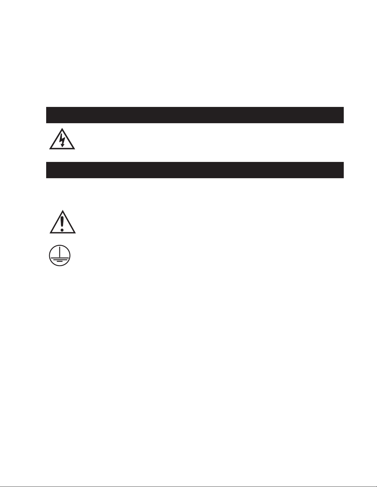
WARNING
DANGEROUS VOLTAGES, capable of causing deat or serious
injury, are present on t e external terminals and inside t e equip-
ment. Use extreme caution and follow all safety rules w en an-
dling, testing or adjusting t e equipment. However, t ese internal
voltage levels are no greater t an t e voltages applied to t e exter-
nal terminals.
DANGER! HIGH VOLTAGE
– This sign warns that the area is connected to a dangerous high voltage, and you
must never touch it.
PERSONNEL SAFETY PRECAUTIONS
The following general rules and other specific warnings throughout the manual must be followed during application,
test or repair of this equipment. Failure to do so will violate standards for safety in the design, manufacture, and intended
use of the product. Qualified personnel should be the only ones who operate and maintain this equipment. Beckwith
Electric Co., Inc. assumes no liability for the customer’s failure to comply with these requirements.
– This sign means that you should refer to the corresponding section of the operation
manual for important information before proceeding.
Always Ground the Equipment
To avoid possible shock hazard, the chassis must be connected to an electrical ground. When servicing
equipment in a test area, the Protective Earth Terminal must be attached to a separate ground securely
by use of a tool, since it is not grounded by external connectors.
Do NOT operate in an explosive environment
Do not operate this equipment in the presence of flammable or explosive gases or fumes. To do so would
risk a possible fire or explosion.
Keep away from live circuits
Operating personnel must not remove the cover or expose the printed circuit board while power is ap-
plied. In no case may components be replaced with power applied. In some instances, dangerous volt-
ages may exist even when power is disconnected.To avoid electrical shock, always disconnect power and
discharge circuits before working on the unit.
Exercise care during installation, operation, & maintenance procedures
The equipment described in this manual contains voltages high enough to cause serious injury or death.
Only qualified personnel should install, operate, test, and maintain this equipment. Be sure that all per-
sonnel safety procedures are carefully followed. Exercise due care when operating or servicing alone.
Do not modify equipment
Do not perform any unauthorized modifications on this instrument. Return of the unit to a Beckwith
Electric repair facility is preferred. If authorized modifications are to be attempted, be sure to follow
replacement procedures carefully to assure that safety features are maintained.

PRODUCT CAUTIONS
Before attempting any test, calibration, or maintenance procedure, personnel must be completely familiar
with the particular circuitry of this unit, and have an adequate understanding of field effect devices. If a
component is found to be defective, always follow replacement procedures carefully to that assure safety
features are maintained. Always replace components with those of equal or better quality as shown in the
Parts List of the Instruction Book.
Avoid static charge
This unit contains MOS circuitry, which can be damaged by improper test or rework procedures. Care
should be taken to avoid static charge on work surfaces and service personnel.
Use caution when measuring resistances
Any attempt to measure resistances between points on the printed circuit board, unless otherwise noted
in the Instruction Book, is likely to cause damage to the unit.

TT
TT
TABLE OF CONTENTSABLE OF CONTENTS
ABLE OF CONTENTSABLE OF CONTENTS
ABLE OF CONTENTS
M-0329B LTC Backup Control
Instruction Book
1.1 Introduction ................................................................................................................... 1
Figure 1 Setpoint Voltage Levels ............................................................................... 1
2.1 Installation .................................................................................................................... 2
Figure 2 Mounting and Outline Dimensions ................................................................
3
3.1 Terminal Block Connections ......................................................................................... 4
F
igure 3 Wire Terminations for External Connections As Required for UL Listing .......
4
Figure 4 External Connections ....................................................................................
4
4.1 Application .................................................................................................................... 5
Figure 5 Power and Voltage Input Connections ..........................................................
5
Figure 6 M-0329B Interconnections with Beckwith
Tapchanger Controls and Regulator ..............................................................................
5
Table 1 TCC Connections ...........................................................................................
6
Figure 7 Interconnections for use with Centrifugal-type Capacitor Drive Motors .........
7
5.1 Adjustment ...................................................................................................................8
6.1 Theory of Operation ...................................................................................................... 8
Power Supply ................................................................................................................ 8
AC/DC Converter .......................................................................................................... 8
Level Detectors ............................................................................................................. 8
Power Supply Monitor ................................................................................................... 8
Lower Time Delay ......................................................................................................... 9
Alarm ............................................................................................................................ 9
Selectable Deadband .................................................................................................... 9
Table 2 Switch Position Settings ................................................................................
9
Figure 8 Schematic ..................................................................................................
10
Figure 9 Block Diagram ............................................................................................
12
7.1 Maintenance ............................................................................................................... 13

8.1 Test Procedure ........................................................................................................... 14
Equipment Required .................................................................................................... 14
Figure 10 Test Setup ................................................................................................
14
Test Setup .................................................................................................................. 15
Procedure for Determining Voltage Bandcenter ........................................................... 15
Test Procedure ........................................................................................................... 15
Bandcenter Test ......................................................................................................... 15
Bandwidth Test ........................................................................................................... 15
Deadband (Block Raise to Block Lower) Test ............................................................. 15
Lower Timer Delay Test .............................................................................................. 15
Fixed Alarm Time Delay Test ..................................................................................... 15
Removing the Printed Circuit Board ............................................................................ 16
Component Replacement Procedure ........................................................................... 16
9.1 Typical Voltages ......................................................................................................... 16
Table 3 Typical Voltages ..........................................................................................
16
10.1 Typical Resistances.................................................................................................... 17
Table 4 Typical Resistances ....................................................................................
17
Figure 11 Component Location .................................................................................
18
11.1 Calibration ................................................................................................................... 19
Parts List .................................................................................................................... 20
800-M0329B-IB-01MC2 09/03
© Beckwith Electric Co., Inc.
Printed in U.S.A. (06.25.02)

–1–
M-0329B Instruction Book
1.1 Introduction
Defective tapchanger controls can create either
too high or too low a voltage along the line, possibly
damaging customer's motors, computers or
televisions. Even when the control is operating
properly, customers close to the transformer may
receive dangerously high voltage as the line drop
compensator attempts to maintain a constant
voltage under heavy load at a central point on the
distribution line. The Beckwith M-0329B LTC
Backup Control can be installed as a solution to
both of these problems.
Designed to replace the Beckwith M-0029 LTC
Control Backup Relay as well as the M-0145 First
Customer Protector, the single-phase, solid-state
M-0329B has three main functions:
1. Prevent a defective LTC tapchanger
control from running the voltage outside
the upper and lower voltage limits.
2. Prevent the line drop compensator from
raising the voltage too high under full
load or overload conditions.
3. Lower the voltage if the regulated voltage
goes above the Block Raise setpoint by
a fixed bandwidth, as shown in Figure 1.
The Block Raise and Block Lower voltage levels
are set by accurately calibrated dials, labeled
BANDCENTER and BANDWIDTH, similar to those
found on LTC transformer controls.
The amount of Deadband between the Block Raise
and the Lower levels can be selected by the
customer, using a switch on the side of the unit.
The BANDCENTER dial has settings from 100 V
rms to 140 V rms that allow the relay to match any
transformer control.
Above the Block Raise level, the relay will detect
voltage above the Lower setpoint. This point is at a
fixed level above the Block Raise, and will initiate a
lower tapchange operation if exceeded for an
adjustable amount of time (1 to 30 sec) as set on
the TIME DELAY control.
Blocking contacts on the M-0329B will operate
within 0.2 seconds after a voltage excursion to
prevent the defective transformer control from
causing another tapchange. After a fixed 3 minute
time delay, if the voltage excursion is still present,
the ALARM contact is activated to indicate control
failure.
Under full or overload conditions, the M-0329B
automatically takes over as an upper voltage limit
control, not affected by load current, to prevent
damage to equipment close to the transformer.
While the Block Raise contact prevents a raise
operation, a Lower contact forces the tapchanger
down if the primary voltage should subsequently
rise.
FIXED DEADBAND
LOWER
BLOCK RAISE
BLOCK LOWER
V
BL
V
BR
V
CBANDCENTER
1/2 BW
1/2 BW
ADJUSTABLE
BANDWIDTH
Figure 1 Setpoint Voltage Levels

–2–
M-0329B Instruction Book
2.1 Installation
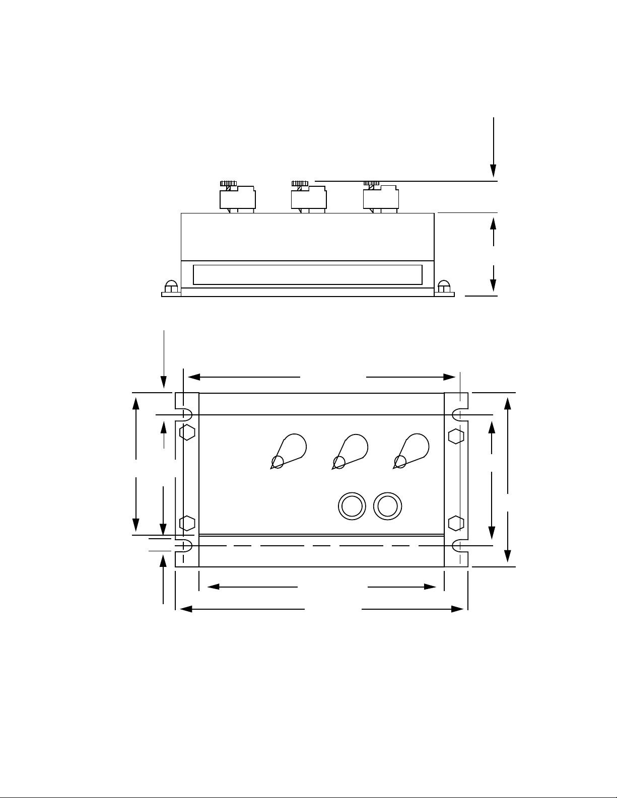
The mounting and outline dimensions are shown
in Figure 2, and the external connections in Figure 4.
■■
■■
■NOTE: TB refers to Terminal Block numbers
shown in Figure 4 External Connections.
The M-0329B can be connected as a two-terminal
device, by paralleling the Power Input (TB1-1 to
TB1-2) and the Voltage (Sensing) Input (TB1-3 to
TB1-4). With this connection, the BANDCENTER
and the BANDWIDTH controls can be set so that
an upper voltage and a lower voltage limit are
established at the desired levels. The M-0329B will
block any further tapchanger raise operations when
the regulated voltage exceeds the upper voltage
limit. Also, if the voltage drops below the lower
limit, the M-0329B will block any further lower
operations. Additionally, if the voltage level
increases above the upper limit (Block Raise) the
M-0329B will lower the voltage, protecting
customers from excessively high voltage levels.
The M-0329B also provides the First Customer
Protection function that previously required a
separate relay. If the LDC raises the local voltage
due to heavy load current, the M-0329B will protect
nearby customers from high voltage, and will act
as an LTC control around the upper voltage limit.
On controls where compensated voltage from the
line drop compensator is available, the M-0329B
can be connected as a four-wire device. The Power
Input should be connected to a 120 V ac source
and the Voltage Input is then connected to the
LDC compensated voltage.
Since sudden changes in the transformer primary
voltage may move the secondary voltage outside
the range of the LTC control and the M-0329B, a 3
minute timer is provided to allow a normal control
to correct the voltage. After 3 minutes of abnormal
voltage, the M-0329B ALARM contact will indicate
an abnormal condition. The BLOCK RAISE/
LOWER LED will be on, the ALARM relay contacts
TB1-14 to TB1-15 will be closed and TB1-15 to
TB1-16 will be open. The ALARM contacts will
also indicate an alarm condition if the AC power to
the M-0329B fails.
The ALARM contacts should be used to alert
system operators that a problem has occurred and
that the LTC transformer or regulator is not
operating. It must be recognized that the ALARM
contacts may operate under conditions of heavy
load using the two-wire connections and the line
drop compensator.
The output blocking contacts should be connected
in series with the raise and lower contacts from the
LTC control. In some control circuits, a timing relay
is used. There, the blocking contacts should be in
series with the timing relay contacts. The blocking
relay contacts should not be connected to drop out
the motor starter relay once it is sealed in for a
tapchange, since most tapchangers should not be
stopped until the tapchange is completed. An
exception to this is a spring-driven tapchanger that
may be stopped at any time. Figure 6 shows the
connections for using the M-0329B with most of
the Beckwith Tapchanger and Regulator Controls.
When power is suddenly changed from raise to
lower, motors with centrifugal starters will continue
to run in the wrong direction without reversing. A
defective control timer, for example, could lead to
this type of runaway situation. Here, the M-0329B
will open up the wrong connection if connected as
described above. The circuit of Figure 7 may be
used instead, where timer relay KX permits the
motor to stop regardless of its direction. It is
assumed that the motor will start in the right direction
once it has stopped.
–3–
M-0329B Instruction Book
1-1/8" Max
(2.86 cm)
2-3/8"
(6.03 cm)
TB1
4-3/4"
(12.07 cm)
8-3/4"
(22.23 cm)
7-3/4"
(19.69 cm)
1/2"
(1.27 cm)
8-1/4"
(20.96 cm)
5-3/4"
(14.61 cm)
4-3/4"
(12.07 cm)
1/4"
(.64 cm)
■■
■■
■NOTE: Panel mount using four #10 bolts
Figure 2 Mounting and Outline Dimensions
–4–
M-0329B Instruction Book
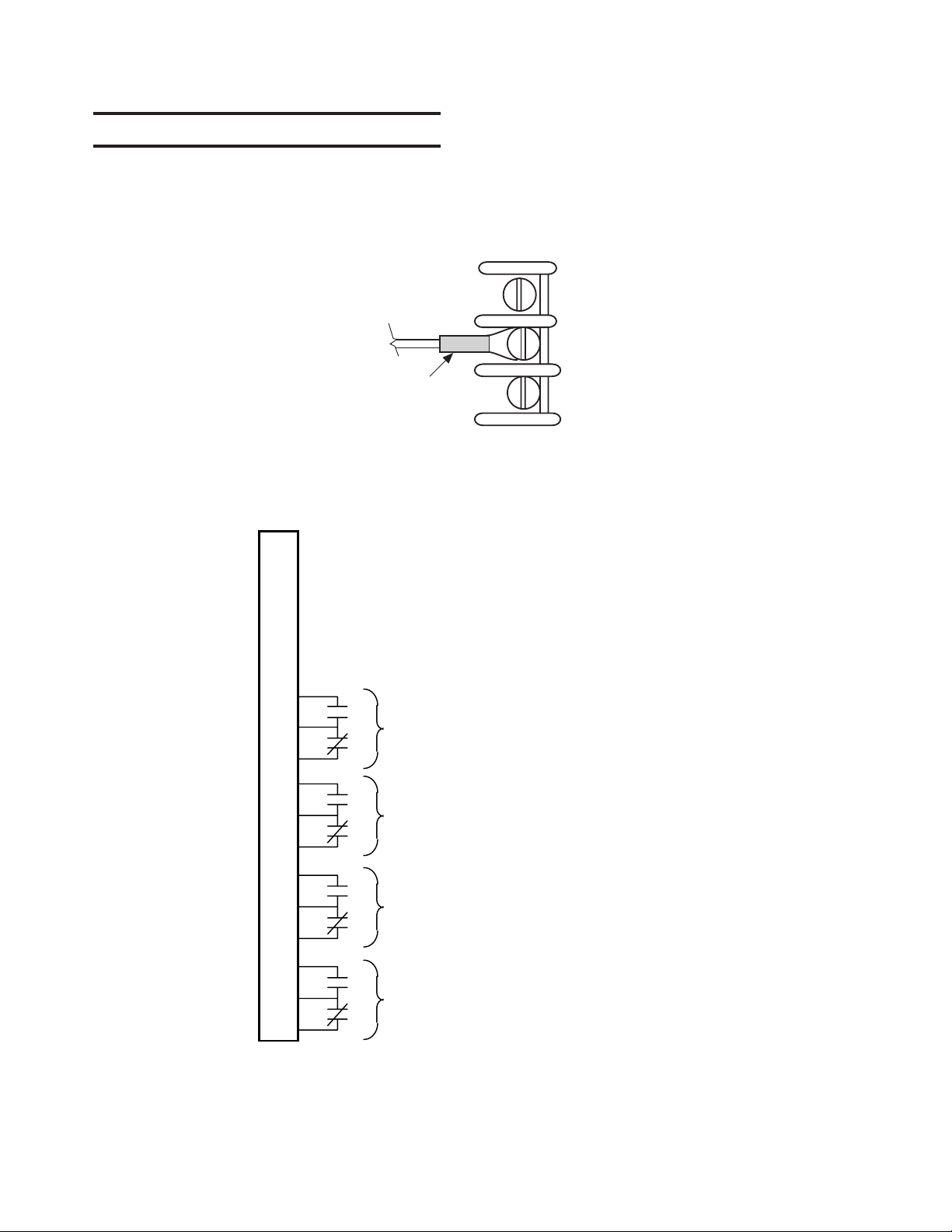
3.1 Terminal Block Connections
The M-0329B LTC Backup Control is listed to UL
Standards for Safety by Underwriters Laboratories
Inc. (UL). To fulfill the UL requirements, terminal
block connections must be made as illustrated in
the figure below. The wire should be No. 16 AWG
inserted in an AMP #51864-1 (or equivalent)
connector, and both screws tightened to 16 inch-
pounds torque.
16 AWG
AMP #51864-1
or equivalent
Recommended Wire Terminations
Tighten to 16 inch-pounds
Figure 3 Wire Terminations for External Connections as Required for UL Listing
1
2
3
4
5
6
7
8
9
10
11
12
13
14
15
16
TB1
•
•
•
•
BLOCK
120 V ac Power Input Hot
120 V ac Power Input Neutral
Voltage (Sensing) Input Hot
Voltage (Sensing) Input Neutral
BLOCK
RAISE
ALARM
LOWER
LOWER
■■
■■
■NOTE: All contacts are shown in the inactive (normal) condition, i.e. the output contact between TB1-14
and TB1-15 is open for the No Alarm condition and will close to indicate an Alarm Condition.
Figure 4 External Connections

–5–
M-0329B Instruction Book
TB1
120 V
1
2
3
4
M-0329
TB1
M-0329
1
2
3
4
LDC VOLTAGE
120 V POWER
Figure 5 Power and Voltage Input Connections
TAPCHANGER CONTROL
90
MOTOR
SUPPLY
R
L
L
c
R
LOWER
BLK RAISE
BLK LOWER
11
12
*
*
6
7
9
10
90 B.U.
C
84R 84L
Limit switcher, auxiliary contacts as
required in motor control circuits.
84R - Raise Motor Auxiliary Relay
84L - Lower Motor Auxiliary Relay
1
120 Vac
POWER
2
3
4
Voltage
14
15
Alarm
■■
■■
■NOTE: *If first customer protection is not required, delete these connections.
Figure 6 M-0329B Interconnections with Beckwith Tapchanger Controls and Regulator
4.1 Application
The M-0329B can be used in many applications
not related to LTC backup for a very accurate
overvoltage and/or undervoltage relay. The Block
Raise (BLK R) and the Block Lower (BLK L)
outputs can be used as overvoltage and
undervoltage outputs, respectively.

–6–
M-0329B Instruction Book
SNOITCENNOCCCT
TINU
SREBMUNLANIMRET
R C L
7602-M/7600-M789
1722-M/)1BT(1720-M596
0722-M/0720-M596
)3BT(0822-M/)2BT(0820-M647
)3BT(8722-M/)2BT(8720-M01911
)1BT(3922-M/3920-M596
)NN(3922-M/3420-M72-NN9-NN82-NN
3230-MLJC
4232-M/4230-M522V32
8330-M01911
)4BT(9332-M/9330-M01911
5430-M21V3
5532-M/5530-M3RmV3L
7530-M51E2E81E
Table 1 TCC Connections
–7–
M-0329B Instruction Book
KX BL
BR
**
BR
1
BL
1
BR
3
BL
3
R
3
BR
2
BL
2
L
2
L
4R
4
5
6
9
8
KX
1
KX
2
KX
R,L
BR, BL
O
New Timer Relay - Delay on pickup to assure motor stops before powering in reverse direction.
Existing Raise and Lower.
New Block Raise and Block Lower Relays.
Terminals on M-0329B Backup Relay.
* M-0329B K1 & K2 Contact
s
shown In Band state.
** Timer Relay Contact
shown before timing out.
* M-0329B K3
Block Lower.
* M-0329B K2
Block Raise.
L
3B
2
Figure 7 Interconnections for use with Centrifugal-Type Capacitor Drive Motors
M-0329 K3
Block Lower

–8–
M-0329B Instruction Book
5.1 Adjustment
Accurately calibrated dials, labeled BANDCENTER
and BANDWIDTH, set the Block Raise and Block
Lower voltage levels. The dials on the M-0329B
cover are calibrated in volts for use with a 120 V ac
nominal voltage.
The following equations will assist the user in
choosing the correct setpoints for the M-0329B.
VBR = the Upper Voltage Limit (Block Raise) desired.
VBL = the Lower Voltage Limit (Block Lower) desired.
The Base Voltage is 120 V ac.
VBR + VBL
The Bandcenter Voltage VC= (1)
2
The Bandwidth VBW = VBR - VBL (2)
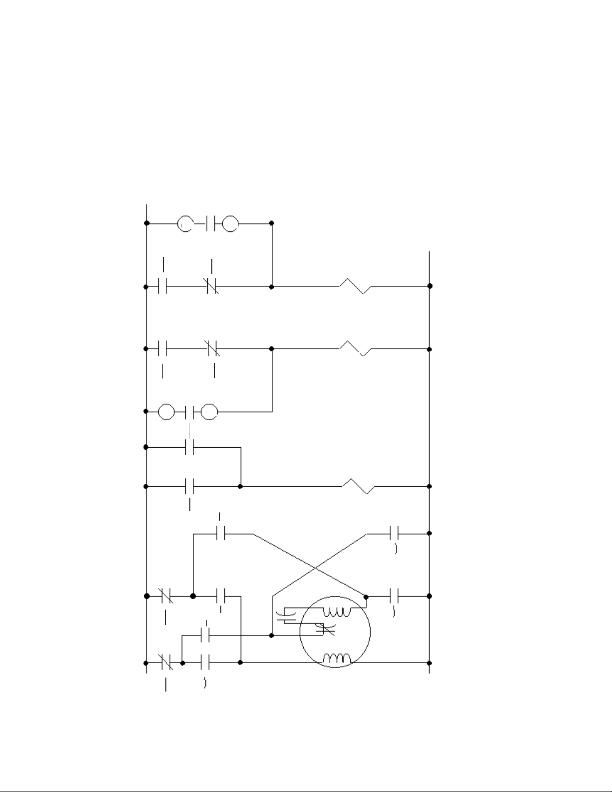
6.1 Theory of Operation
Refer to Figure 8, Schematic and Figure 9, Block
Diagram.
Power Supply
The Power Supply converts the 120 V ac power
input to the dc voltages required for the M-0329B
circuitry. Components C1 and RV1 are used to
suppress transverse-mode transients on the input.
RV2 and RV3 are common-mode suppressors that
allow up to 1500 V rms common-mode voltage but
will clip any transients above this level. T1 converts
the 120 V ac input to 36 V ac, center-tapped at
T1-4. T1 also employs a Faraday shield that isolates
the secondary windings from common-mode
transients on the primary.
Diodes CR1 through CR4 form a full-wave recti-
fier that produces +24 V dc and -24 V dc from
the secondary of T1. Capacitors C2 and C3 filter
the ac ripple off the +24 V dc; C7 smooths out
the -24 V dc. VR1 is a zener diode that clips off,
to a safe level, any transients that may remain
on the +24 V dc, protecting U1 and U5.
U1 converts the +24 V dc to a precision +10.00 V dc
reference voltage for use by the internal circuitry.
The +V supply is a +15 V dc level formed by U5,
R102, R103, C19 & C4. The -15 V is a zener diode
supply using VR3 and dropping resistor R9.
AC/DC Converter
The Voltage Input, TB1-3 to TB1-4, is the voltage
that the M-0329B will monitor to provide the voltage
protection functions described previously. The input
protection circuitry for the Sensing Input is the
same used for the Power Input. Transformer T2
steps down the input level to a lower level used by
the Ac/Dc Converter. U2-1, U2-7 and associated
circuitry form a precision active full-wave rectifier/
filter that converts the ac Sensing Input to a dc
voltage that is proportional to the average voltage
level of the Sensing Input. This dc level at U2-1 is
offset by the BANDCENTER adjustment network,
consisting of R3, R16, R17, R15 and R14; so that
the voltage at U2-1 equals +5.0 V dc when the
Sensing Input level is equal to the setting of the
BANDCENTER dial. Any variation of the input level
from the BANDCENTER setting will cause the U2-1
voltage to deviate from +5.0 V dc by approximately
0.072 V dc/%.
Level Detectors
The Level Detector circuits compare the dc voltage
from U2-1 to dc levels set by the BANDWIDTH
control. R21 and R4 are used in a voltage-divider
circuit to establish the bandwidth. The voltage
across R21 and R4 is centered around +5.00 V dc
so that a symmetrical band is formed around the
BANDCENTER setting. If the U2-1 voltage rises
above the voltage at U2-9, the output at U2-8 goes
high to block any further raise operations of the
tapchanger. If the voltage drops below the level at
U2-12, the voltage at U2-14 goes high, blocking
any further lower operations of the LTC. When the
U2-1 output voltage exceeds the level at U3-6, the
voltage at U3-7 goes high, lighting the LOWER
LED and initiating a lower operation. R23 through
R28 provide a small amount of hysteresis at each
of the voltage levels in order to avoid oscillations in
the level detector outputs.
Power Supply Monitor
The Power Supply Monitor is used to delay the
operation of the BLK R, BLK L, and LOWER relays
for approximately 2 seconds when power is applied.
This eliminates any relay chatter when the M-0329B
is put in service. Also, this circuit monitors the level
of the Power Input and disables the above relays if
the voltage level is below 75 V ac.

–9–
M-0329B Instruction Book
Amplifier U3-1 and associated components form
the voltage level detector that monitors the +24 V
dc level. If the level is below 13.7 V dc, the output at
U3-1 will be low, forcing the output at U4-10 low.
This disables the three relay drive circuits for K1,
K2, and K3. When the +24 V dc level exceeds
14.8 V dc, the output at U3-1 will be high, enabling
the relay drive circuits.
Components R32 and C15 provide the Power Up
delay. C15 is discharged when the power is off.
When power is applied, C15 is charged from +V
through R32. When the voltage on C15 reaches
one half the +V level, the U4-10 output is enabled.
If the voltage at U4-9 is also high, then the output at
U4-10 will go high. This enables the other three U4
gates so that the level detector outputs are enabled
to control the output relays.
Lower Time Delay
Op Amp U3-14 and associated components form
an adjustable time delay for the LOWER relay
operation. By adjusting the TIME DELAY control, a
voltage level is established at the wiper of R5 which
determines the length of the time delay. When the
output at U4-11 goes high, C16 begins charging
through R39. CR14 blocks charging current from
flowing through R38. When the voltage at U3-12
reaches the level set by R5, the output at U3-14
goes high, turning on Q2 and energizing K1. R40
and R41 provide the positive feedback to prevent
oscillations. The length of the time delay is
determined by the setting of R5.
Alarm
The ALARM relay provides an indication that the
M-0329B is in a blocking condition or that the power
is off. Relay K4 is normally energized when there is
no Alarm condition. When K4 is de-energized, an
Alarm is generated by the closing of TB1-14 to
TB1-15 and the opening of TB1-15 to TB1-16.
Therefore, if power to the M-0329B is off, an Alarm
is generated.
In the normal (No Alarm) condition, the output of
U3-8 is high, turning on Q5 through R54 and CR22.
This condition will remain as long as the outputs of
U4-4 and U4-3 remain low. When either of these
goes high, C17 is charged by this voltage through
R50. After 3 minutes, the voltage on C17 will exceed
the voltage established at U3-10, causing the output
at U3-8 to go low, generating an Alarm.
Selectable Deadband
Switch S1 controls the deadband voltage selection.
When position 1 is up and positions 2, 3, and 4 are
down, the deadband selection is 1 V. When position
2 is up and positions 1, 3, and 4 are down, the
deadband selection is 2 V. If more than one switch
is in the “up” position, the control's operation and
deadband setting will be unpredictable.
noitisoPhctiwS
dnabdaeD
gnitteS 1-1S2-1S3-1S4-1S
V1 pU nwoDnwoDnwoD
V2nwoD pU nwoDnwoD
V3nwoDnwoD pU nwoD
V4nwoDnwoDnwoD pU
Table 2 Switch Position Settings

–10–
M-0329B Instruction Book
U2D
LM224
12
13 14
+
-
R6
10
2W,5
CR5
1N4004
TP12
TP8
R25
1K
1/4W,5
R27
9.1K
1/4W,5
T1
U-0256
111
4
28
6
C9
.01uf
125V
R24
330K
1/8W,5
C13
.68uf
50V
R28
7.5M
1/8W,1
U2A
LM224
3
21
+
-
CR7
1N4148
TP6
RV4
250V
R1
100K
1/8W,1
R26
750K
1/8W,1
R14
182K
1/8W,1
R23
1K
1/4W,5
R11
24.9K
1/8W,1
R2
100K
1/8W,1
U2B
LM224
5
67
4
11
+
-
RV5
1KV
C11
.1uf
50V
C12
3.3uf
50V
C4
.01uf
50V
C10
2500pf 1KV
CR9
1N4148
CR10
1N4148
R12
66.5K
1/8W,1
R58
41.2
1/8W,1
S1
DPST
1
16
2
15
3
4
5
6
7
8
14
13
12
11
10
9
R59
16.5
1/8W,1
TP1
R60
0
1/8W,1
R10
49.9K
1/8W,1
R103
1.37K
1/4W,1
R20
24.3
1/8W,1
TP3
TP7
R102
124
1/4W,1
R61
48.7
1/8W,1
TP4
R62
73.2
1/8W,1
TP5
T2
U-0255
212
57
10
R63
97.6
1/8W,1
CR12
1N4148
TB1-4
4
R21
102
1/8W,1
F2
1/2A
TP21
TB1-3 3
TP2
C8
.01uf
125V
RV6
275V
JP2
C19
1uf
50V
R13
24.9K
1/8W,1
R18
1.78K
1/8W,1
JP1
VR1
1N5365B
36V
CR6
1N4004
C7
470uf
50V
+
CR2
1N4004
CR3
1N4004
CR4
1N4004
C2
.05uf
600V
C3
470uf
50V
+
CR13
1N4148
U5
LM317
VIN
3
ADJ
1
VOUT 2
U1
LH0070
IN
1OUT 2
GND
3
C18
.01uf
50V
C6
.01uf
50V
C5
.01uf
50V
CR1
1N4004
VR3
CMZ5929B
15V
(1N965B)
R19
64.9
1/8W,1
R44
3.9K
1/4W,5
CR8
1N4148
U3B
TLC274
5
67
+
-
C1
.01uf
125V
RV2
1KV
RV3
275V
F1
1A
TB1-1 1
RV1
250V
TB1-2 2
R9
1.5K
2W,10
U2C
LM224
10
98
+
-
-15V
+10V
-15V
+24V
+15V
+10V
+10V -15V
-24V
+15V
HOT
NEUTRAL
POT.
INPUT
HOT
NEUTRAL
120VAC
X2
X3
X4
X5
X6
X7
X1
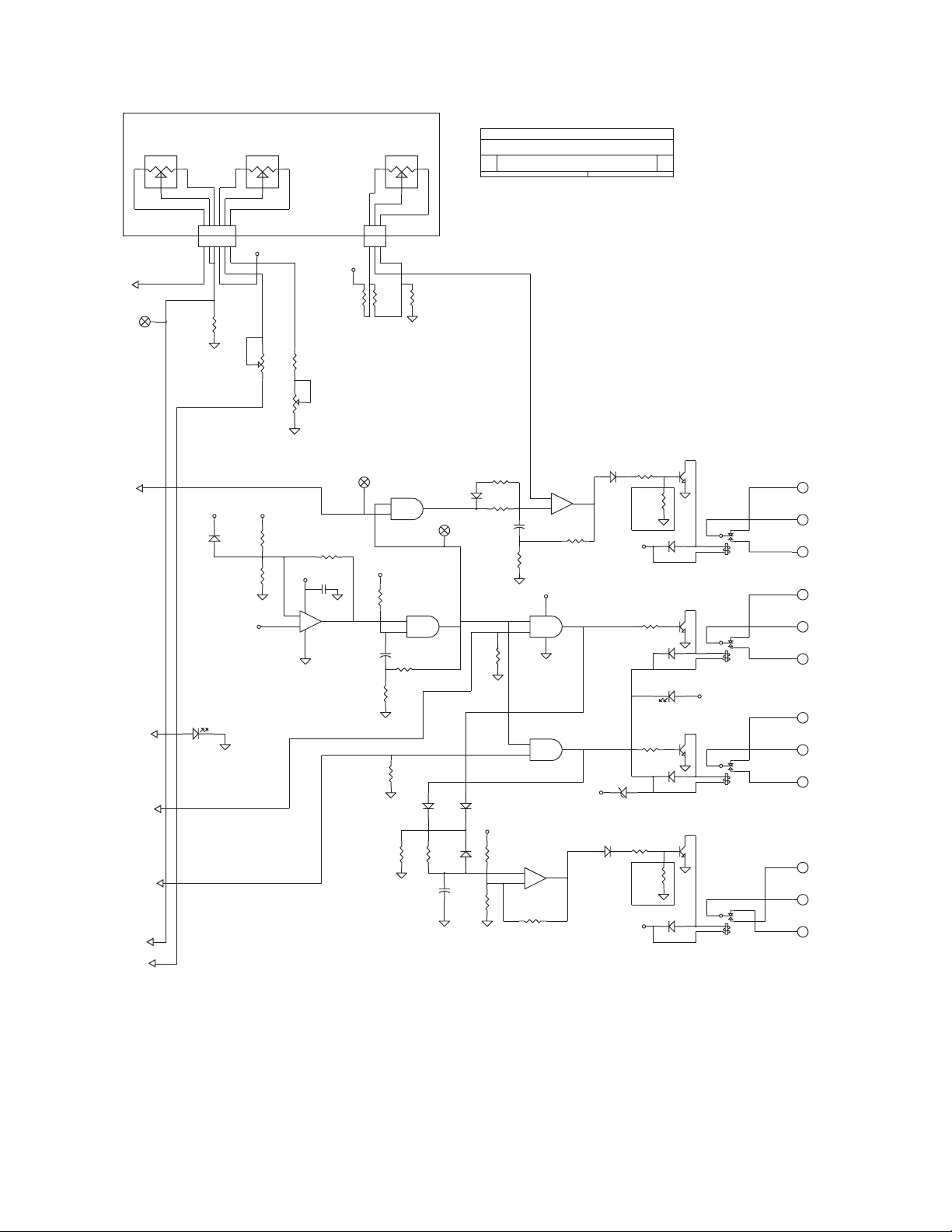
Figure 8 Schematic
–11–
M-0329B Instruction Book
R45
100K
1/4W,5
TB1-14
14
TP10
TB1-16
16
TP11
R80
K4
T75-24VDC
54
3
1
2
R29
100K
1/4W,5
R52
182K
1/8W,1
Q5
2N2222A
2
1
3
R54
20K
1/4W,5
U3A
TLC274
3
2
1
4
11
R35
53.6K
1/8W,1
R51
39.2K
1/8W,1
R30
267K
1/8W,1
CR18
1N4148
R36
56.2K
1/8W,1
R37
2.37
1/8W,1
Q4 2N2222A
2
1
3
CR25
LED
Q3 2N2222A
2
1
3
2N2222A
2
1
3
R38
10K
1/4W,5
C17
4.7uf
63V
R39
10M
1/4W,5
R49
20K
1/4W,5
R50
20M
1/4W,5
CR23
1N4148
R4
500
R16
750
1/8W,1
TLC274
1
9
8
+
-
R47
100K
1/4W,5
CR15
1N4004
P1
C16
4.7uf
63V
R22
1.87K
1/8W,1
R40
100K
1/4W,5
TB1-12
12
TB1-11
11
TB1-13
13
K1
T75-24VDC
5
4
3
1
2
R43
5.1K
1/4W,5
R3
2K
R41
1K
1/4W,5
R5
500K
J2
3
2
1
CR11
1N4148
R33
100K
1/4W,5
CR19
1N414
R34
2K
1/4W,5
CR17
1N4148
C15
4.7uf
25V
+
TB1-6
6
R46
15K
1/4W,5
TB1-8
8
TB1-5
5
TB1-9
9
C14
.1uf
50V
J1
6
5
4
3
2
1
TB1-7
7
TB1-10
10
K3
T75-24VDC
5
4
3
1
2
CR21
MMBD1501/A
U4D
4081
12
13
11
R48
15K
1/4W,5
U4B
4081
5
6
4
14
7
TP9
U4C
4081
8
9
10
U4A
4081
1
23
CR24
LED
P2
1
2
3
R32
510K
1/4W,5
VR4
CMPZ5227B
(1N747A)
3.6V
R15
50K
1/2W,20
R81
?
CR16
1N4148
U3D
TLC274
12
13 14
CR22
1N4004
CR20
1N4148
K2
T75-24VDC
5
4
3
1
2
R31
680K
1/4W,5
CR14
MMBD1501/A
R56
3.9M
1/4W,5
TB1-15
15
R17
200
1/2W,20
+24V
+24V
+24V
+24V
+10V
+15
+15V
+15V
+24V
+15V
+10V
+15V
+15V
BANDCENTER
VOLTS
BANDWITH
VOLTS
TIME DELAY
SECONDS
LOWER
BLOCK
RAISE
BLOCK
LOWER
BLOCKING
ALARM
LOWER
BLOCK RAISE / LOWER
FUTURE
FRONT PANEL
CONNECTIONS
X1
X2
X3
X4
X5
X6
X7
X-0329B B
LTC BACKUP CONTROL
D
Table of contents
Other BECKWITH ELECTRIC Protection Device manuals


