BECKWITH ELECTRIC M-3425 User manual
Instruction Book
M-3425
Generator Protection

Generator Protection
M-3425
Integrated Protection System®for Generators of All Sizes
• Provides all major protective functions for generator protection, including
Field Ground (64F), Out-of-Step (78), and Split-Phase Differential (50DT)
• Expanded IPScom®Communications Software provides simple and logical
setting and programming
• Enhanced "pick and choose" functionality provides tailored applications at
the lowest possible cost
Unit shown with optional M-3925 Target Module and M-3931
HMI (Human-Machine Interface) Module.
PROTECTION

–2–
M-3425 Generator Protection Relay
Standard Protective Functions
• Dual-zone phase distance protection for
phase fault backup (21)
• Overexcitation (V/Hz) protection (24)
• Phase Undervoltage (27) protection
• 100%StatorGroundFaultprotectionviathird
harmonic neutral undervoltage (27TN)
• Sensitive dual-setpoint Reverse Power, Low
Forward Power or Overpower detection, one
of which can be used for sequential tripping
(32)
• Dual-zone, offset-mho Loss-of-Field
protection (40)
• Sensitive Negative Sequence Overcurrent
protection and alarm (46)
• Instantaneous Overcurrent (50) protection
• Inadvertent Generator Energizing protection
(50/27)
• GeneratorBreaker Failure protection (50BF)
• Definite Time Overcurrent (50DT) can be
used for split phase differential
• Instantaneous Overcurrent (50N) protection
• Neutral Inverse Time Overcurrent (51N)
• Three-phaseInverseTimeOvercurrent(51V)
• Phase Overvoltage (59)
• Generator Ground Fault protection (59N)
• VT Fuse-Loss detection and blocking
(60FL)
• Out-of-Step protection (78)
• Four-stepOver/Underfrequency (81) protec-
tion
• Two-stepRateofChangeofFrequency(81R)
• Generator Phase Differential protection (87)
• Ground Differential (87GD) protection
• External Function allows external devices to
trip through M-3425 Generator Protection
Relay
Optional Protective Functions
• Stator Thermal protection using positive se-
quence inverse time overcurrent (51T)
• Field Ground protection (64F)
Standard Features
• Eightprogrammable outputs andsixprogram-
mable inputs
• Oscillography recording
• Time-stamped target storage for 24 events
• Metering of all measured parameters
• Threecommunications ports(twoRS-232and
oneRS-485)
• M-3820CIPScom®CommunicationsSoftware
• IncludesMODBUSandBECO2200 protocols
• Standard19"rack-mount design
• Removable printed circuit board and power
supply
• Both 50 and 60 Hz models available
• Both 1A and 5 A rated CT inputs available
• Additionaltrip inputs for externally connected
devices
• IRIG-B time synchronization
• Operating Temperature: –20° C to +70° C
Optional Features
• Redundant power supply
• M-3925 Target Module
• M-3931 Human-Machine Interface (HMI)
Module
• M-3801C IPSplot®Oscillograph Analysis
Software

–3–
M-3425 Generator Protection Relay
STANDARD PROTECTIVE FUNCTIONS
Device Setpoint
Number Function Ranges Increment Accuracy†
Phase Distance (dual-zone mho characteristic)
Circle Diameter #1, #2 0.1 to 100.0 Ω0.1 Ω!0.1 Ωor 5%
(0.5 to 500.0 Ω)(!0.5 Ωor 5%)
Offset #1, #2 –100.0 to 100.0 Ω0.1 Ω!0.1 Ωor 5%
(–500.0 to 500.0 Ω)(!0.5 Ωor 5%)
Impedance Angle #1, #2 0° to 90° 1° !1°
Time Delay #1, #2 1 to 8160 Cycles 1 Cycle !1 Cycle or !1%
Volts / Hz
Definite Time
Pickup #1, #2 100 to 200% 1% !1%
Time Delay #1, #2 30 to 8160 Cycles 1 Cycle !25 Cycles
Inverse Time
Characteristic Curves Inverse Time #1–#4 — —
Pickup 100 to 200% 1% !1%
Time Dial: Curve #1 1 to 100 1
Time Dial: Curves #2–#4 0.0 to 9.0 0.1
Reset Rate 1 to 999 Sec. 1 Sec. !.02 Sec. or !1%
(from threshold of trip)
The percent pickup is based on nominal VT secondary voltage and nominal system frequency settings. The
pickup accuracy stated is only applicable from 10 to 80 Hz, 0 to 180 V, 100 to 150% V/Hz and a nominal voltage
setting of 120 V.
Third-Harmonic Undervoltage, Neutral
Pickup #1, #2 0.3 to 20.0 V 0.1 V !0.15 V or !1%
Time Delay #1, #2 1 to 8160 Cycles 1 Cycle !1 Cycle or !1%
Undervoltage Inhibit #1,#2 5 to 180 V 1 V !0.5 V or 0.5%
(positive sequence)
Underpower Inhibit #1,#2 0.002 to 3.000 PU 0.001 PU !0.002 or !2%
RMS Undervoltage
Pickup #1, #2 5 to 180 V 1 V !0.5 V or !0.5%
!0.8 V or !0.75%*
Time Delay #1, #2 1 to 8160 Cycles 1 Cycle !1 Cycle or !0.5%**
* When both RMS and Line-Ground to Line-Line is selected.
*When RMS (total waveform) is selected, timing accuracy is +20 cycles or
!
1%
†
.
Directional Power
Pickup #1, #2 –3.000 to +3.000 PU 0.001 PU !0.002 PU or !2%
Time Delay #1, #2 1 to 8160 Cycles 1 Cycle +16 Cycles or !1%
The per-unit pickup is based on nominal VT secondary voltage and nominal CT secondary current settings. The
32 function can be selected as low forward power, reverse power, or overpower function.
†Select the greater of these accuracy values. Values in parentheses apply to 1 A CT secondary rating.
27
32
21
24
27
TN
27
32

–4–
M-3425 Generator Protection Relay
STANDARD PROTECTIVE FUNCTIONS (
cont
.)
Device Setpoint
Number Function Ranges Increment Accuracy†
Loss of Field (dual-zone offset-mho characteristic)
Circle Diameter #1, #2 0.1 to 100.0 Ω0.1 Ω!0.1 Ωor !5%
(0.5 to 500.0 Ω)(!0.5 Ωor !5%)
Offset #1, #2 –50.0 to 50.0 Ω0.1 Ω!0.1 Ωor !5%
(–250.0 to 250.0 Ω)(!0.5 Ωor !5%)
Time Delay #1, #2 1 to 8160 Cycles 1 Cycle !1 Cycle or !1%
Voltage Control 5 to 180 V 1 V !0.5 V or !0.5%
(positive sequence)
Directional Element Fixed at –13° — —
Voltage control for each zone can be individually enabled.
Negative Sequence Overcurrent
Definite Time
Pickup 3 to 100% 1% !0.5% of 5 A
(!0.5% of 1 A)
Time Delay 1 to 8160 Cycles 1 Cycle !1 Cycle or !1%
Inverse Time
Pickup 3 to 100% 1% !0.5 % of 5 A
(!0.5% of 1 A)
Time Dial Setting 1 to 95 1 !3 Cycles or !3%
(K= I22t)
Definite Maximum
Time to Trip 600 to 65,500 Cycles 1 Cycle !1%
Definite Minimum Time 12 Cycles — fixed
Reset Time (Linear) 4 minutes — —
(from threshold of trip)
Pickup is based on the generator nominal current setting.
Breaker Failure
Pickup
Phase Current 0.10 to 10.00 A 0.01 A !0.1 A or !2%
(0.02 to 2.00 A) (!0.02 A or !2%)
Neutral Current 0.10 to 10.00 A 0.01 A !0.1 A or !2%
(0.02 to 2.00 A) (!0.02 A or !2%)
Time Delay 1 to 8160 Cycles 1 Cycle !1 Cycle or !1%
50BF can be initiated from designated M-3425 output contacts or progammable inputs.
Instantaneous Overcurrent
Pickup 0.1 to 240.0 A 0.1 A !0.1 A or !3%
(0.1 to 48.0 A) (!0.02 A or !3%)
Trip Time Response < 2 Cycles
†Select the greater of these accuracy values. Values in parentheses apply to 1 A CT secondary rating.
40
46
50
BF
50
50
BF-Ph
50
BF-N

–5–
M-3425 Generator Protection Relay
STANDARD PROTECTIVE FUNCTIONS (
cont
.)
Device Setpoint
Number Function Ranges Increment Accuracy†
Instantaneous Overcurrent, Neutral
Pickup 0.1 to 240.0 A 0.1 A !0.1 A or !3%
(0.1 to 48.0 A) (!0.02 A or !3%)
Trip Time Response < 2 Cycles
Definite Time Overcurrent
Pickup Phase A #1, #2 0.20 A to 240.00 A 0.01 !0.1 A or !3%
(0.04 A to 48.00 A) (!0.02 A or !3%)
Pickup Phase B #1, #2 (same as above)
Pickup Phase C #1, #2 (same as above)
Time Delay #1, #2 1 to 8160 Cycles 1 Cycle !1 Cycle or !1%
When 50DT function is used for split-phase differential protection, 50BF, 87, and 87GD functions are not
available.
Inadvertent Energizing
Overcurrent
Pickup 0.5 to 15.00 A 0.01 A !0.1 A or !2%
(0.1 to 3.00 A) (!0.02 A or !2%)
Undervoltage
Pickup 40 to 130 V 1 V !0.5 V
Pick-up Time Delay 1 to 8160 Cycles 1 Cycle !1 Cycle or !1%
Drop-out Time Delay 1 to 8160 Cycles 1 Cycle !1 Cycle or !1%
Inverse Time Neutral Overcurrent
Pickup 0.25 to 12.00 A 0.01 A !0.1 A or !1%
(0.05 to 2.40 A) (!0.02 A or !1%)
Characteristic Curve Definite Time/Inverse/Very Inverse/Extremely Inverse/IEC Curves
Time Dial 0.5 to 11.0 0.1 !3% or !3 Cycles
0.05 to 1.10 (IEC curves) 0.01
Inverse Time Overcurrent, with Voltage Control or Voltage Restraint
Pickup 0.5 to 12.0 A 0.01 A !0.1 A or !1%
(0.10 to 2.40 A) (!0.02 A or !1%)
Characteristic Curve Definite Time/Inverse/Very Inverse/Extremely Inverse/IEC Curves
Time Dial 0.5 to 11.0 0.1 !3% or !3 Cycles
0.05 to 1.10 (IEC curves) 0.01
Voltage Control (VC) 5 to 180 V 1 V !0.5 V or !0.5%
or
Voltage Restraint (VR) Linear Restraint — —
†Select the greater of these accuracy values. Values in parentheses apply to 1 A CT secondary rating.
51V
51N
50/
27
50
DT
50N
50
27

–6–
M-3425 Generator Protection Relay
STANDARD PROTECTIVE FUNCTIONS (
cont
.)
Device Setpoint
Number Function Ranges Increment Accuracy†
RMS Overvoltage
Pickup #1, #2 5 to 180 V 1 V !0.5 V or !0.5%
!0.8 V to !0.75%*
Time Delay #1, #2 1 to 8160 Cycles 1 Cycle !1 Cycle or !1%**
*When both RMS and Line-Ground to Line-Line is selected.
**When RMS (total waveform) is selected, timing accuracy is +20 cycles or
!
1%.
RMS Overvoltage, Neutral
Pickup #1, #2 5.0 to 180.0 V 0.1 V !0.5 V to !0.5%
Time Delay #1, #2 1 to 8160 Cycles 1 Cycle !1 Cycle or !1%
VT Fuse-Loss Detection
A VT fuse-loss condition is detected by using the positive and negative sequence components
of the voltages and currents. VT fuse-loss output can be initiated from internally generated logic
or from input contacts.
Time Delay 1 to 8160 Cycles 1 Cycle !1 Cycle or !1%
Out of Step (mho characteristic)
Circle Diameter 0.1 to 100.0 Ω0.1 Ω!0.1 Ωor 5%
(0.5 to 500.0 Ω)(!0.5 Ωor 5%)
Offset –100.0 to 100.0 Ω0.1 Ω!0.1 Ωor 5%
(–500.0 to 500.0 Ω)(!0.5 Ωor 5%)
Impedance Angle 0° to 90° 1° !1°
Blinder 0.1 to 50.0 Ω0.1 Ω!0.1 Ωor 5%
(0.5 to 250.0 Ω)(!0.5 Ωor 5%)
Time Delay 1 to 8160 Cycles 1 Cycle !1 Cycle or !1%
Trip on mho Exit Enable/Disable
Pole Slip Counter 1 to 20 1
Pole Slip Reset 1 to 8160 Cycles 1 Cycle !1 Cycle or !1%
Frequency
Pickup #1,#2,#3,#4 50.00 to 67.00 Hz 0.01 Hz !0.02 Hz
40.00 to 57.00 Hz*
Time Delay #1–#4 2 to 65,500 Cycles 1 Cycle !2 Cycles or !1%
The pickup accuracy applies to 60 Hz models at a range of 57 to 63 Hz, and to 50 Hz models at a range of 47 to
53 Hz. Beyond these ranges, the accuracy is
!
0.1 Hz.
* This range applies to 50 Hz nominal frequency models.
†Select the greater of these accuracy values. Values in parentheses apply to 1 A CT secondary rating.
59
59N
60
FL
81
78

–7–
M-3425 Generator Protection Relay
STANDARD PROTECTIVE FUNCTIONS (
cont
.)
Device Setpoint
Number Function Ranges Increment Accuracy†
Rate of Change of Frequency
Pickup #1, #2 0.10 to 20.00 Hz/Sec. 0.01 Hz/Sec. !0.05 Hz/Sec. or !5%
Time Delay #1, #2 1 to 8160 Cycles 1 Cycle !20 Cycles
Negative Sequence
Voltage Inhibit 0 to 99% 1% !0.5%
Phase Differential Current
Pickup 0.20 A to 3.00 A 0.01 A !0.1 A or !5%
(0.04 to 0.60 A) (!0.02 A or !5%)
Percent Slope 1 to 100% 1% !2%
Time Delay* 1 to 8160 Cycles 1 Cycle !1 Cycle or !1%
*When a time delay of 1 cycle is selected, the response time is less than 1–1/2 cycles.
Ground (zero sequence) Differential
Pickup 0.20 to 10.00 A 0.01 A !0.1 A or !5%
(0.04 to 2.00 A) (!0.02 A or !5%)
Time Delay 1 to 8160 Cycles 1 Cycle !1 Cycle or !1%
CT Ratio Correction (RC) 0.10 to 7.99 0.01
The 87GD function is provided primarily for low-impedance grounded generator applications. This function
operates as a directional differential. If 3I
0
or I
n
is extremely small (less than 0.2 secondary Amps), the directional
element is disabled.
External Functions
Two functions are provided for externally connected devices to trip through the relay to provide
additional logic and target information. Any one or more of the input contacts (IN1–IN6) can be
programmed to activate designated output contacts after a selected time delay.
Time Delay #1, #2 1 to 8160 Cycles 1 Cycle !1 Cycle or !1%
Nominal Settings
Nominal Voltage 50 to 140 V 1 V —
Nominal Current 0.50 to 6.00 A 0.01 A —
VT Configuration Line-Line/Line-Ground/
Line-Ground to Line-Line*
Seal-In Delay 2 to 8160 Cycles 1 Cycle !1 Cycle or !1%
*When Line-Ground to Line-Line is selected, the relay internally calculates the line-line voltage from the line-ground
voltages for all voltage-sensitive functions. This Line-Ground to Line-Line selection should only be used for a VT
nominal secondary voltage of 69 V (not 120 V).
†Select the greater of these accuracy values. Values in parentheses apply to 1 A CT secondary rating.
81R
87
87
GD
EXT

–8–
M-3425 Generator Protection Relay
†Select the greater of these accuracy values. Values in parentheses apply to 1 A CT secondary rating.
OPTIONAL PROTECTIVE FUNCTIONS
Device Setpoint
Number Function Ranges Increment Accuracy†
Inverse Time Positive Sequence Overcurrent (I2t=K),
for Stator Thermal Protection
Pickup 0.50 to 15.00 A 0.01 A !0.1 A
(0.10 to 3.00 A) (!0.02 A)
Time Delay @6X* 0.10 to 10.00 Sec. 0.01 Sec. !3% or 3 Cycles
Reset Characteristics 4 minutes — !3%
(Linear) (from threshold of trip)
*This time delay setting is at six times the pickup current.
Field Ground Protection
Pickup #1, #2 5 to 100 KΩ1 KΩ!10% or ±1KΩ
Time Delay #1, #2 1 to 8160 Cycles 1 Cycle !(2
IF +1) Sec.
Injection Frequency (IF) 0.10 to 1.00 Hz 0.01 Hz
Brush Lift-Off Detection (measuring control circuit)
Pickup 0 to 5000 mV 1 mV
Time Delay 1 to 8160 Cycles 1 Cycle !(2
IF +1) Sec.
When 64F is purchased, an external Coupler Module (M-3921) is provided for isolation from dc field voltages.
Figure 9, Typical Field Ground Connection Diagram, illustrates a typical connection utilizing the M-3921 Field
Ground Coupler. Hardware dimensional and mounting information is shown in Figure 10, M-3921 Field Ground
Coupler Mounting Dimensions.
64F
64B
51T

–9–
M-3425 Generator Protection Relay
Description
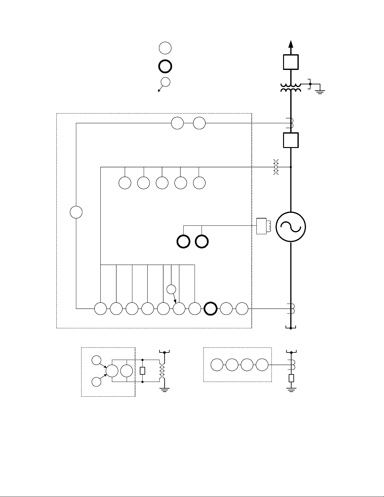
TheM-3425GeneratorProtection Relay is suitable for all generator ratings and prime movers. Typical connection
diagrams are illustrated in Figure 2, M-3425 Typical One-Line Connection Diagram, Figure 3, M-3425 Typical
One-LineConnectionDiagram(ConfiguredforSplit-Phase Differential), and Figure 4, M-3425 Typical Three-Line
ConnectionDiagram.
Configuration Options
The M-3425 Generator Protection Relay is available with Standard Protective Functions, Optional Protective
Functions, and Optional Features. This provides the user flexibility in selecting a protective system to best suit
the application. The relay may be purchased as a Protection System which includes all Standard Protective
Functions. Additional Optional Protective Functions may be added at the time of purchase at per-function
pricing.
The relay may also be purchased as a Base System, with the user selecting any ten (10) Standard Protective
Functions. Additional Standard Functions and/or Premium Protective Functions may be added at the time of
purchase at per-function pricing.
The user can select the Human-Machine Interface (HMI) Module, Target Module, or redundant power supply at
time of purchase for either the Protective System or Base System options.
When the user purchases the Field Ground (64F) Premium Protective Function, an external coupler module
(M-3921) is provided for isolation from the dc field voltages.
Metering
The relay provides metering of voltages (phase, neutral and sequence quantities), currents (phase, neutral and
sequence quantities), real power, reactive power, power factor and impedance measurements.
Meteringaccuraciesare:
Voltage: !0.5 V or !0.5%, whichever is greater
!0.8 V or !0.75%, whichever is greater (when both RMS and Line-Ground to Line-Line are
selected)
Current: 5 A rating, !0.1 A or !3%, whichever is greater
1 A rating, !0.02 A or !3%, whichever is greater
Power: !0.01 PU or !2%, whichever is greater
Frequency: !0.02 Hz (from 57 to 63 Hz for 60 Hz models; from 47 to 53 Hz for 50 Hz models)
Oscillographic Recorder
Theoscillographicrecorderprovidescomprehensive data recording of all monitored waveforms, storing up to 170
cyclesofdata. The total record length is user-configurable for1,2, 3 or 4 partitions. The sampling rateis16times
the power system nominal frequency (50 or 60 Hz). The recorder may be triggered either via the designated
status inputs, trip outputs, or via serial communications. The recorder continuously stores waveform data,
keepingthe most recent data inmemory. When triggered, the recorderstores pre-trigger data, thencontinues to
storedata in memory fora user-defined, post-trigger delayperiod.
The records may be analyzed or viewed using Beckwith Electric IPSplot®Oscillograph Analysis software or
M-3813 ComVert software, which converts Beckwith Electric oscillographic files to COMTRADE format.
Target Storage
Atotal of 24 targetscan be stored. The informationwill include the function(s)operated, the functions picked up,
input/output status, time stamp, and phase and neutral currents at the time of trip.
Calculations
Current and Voltage RMS Values
: Uses discrete Fourier transform algorithm on sampled voltage and current
signals to extract fundamental frequency phasors for relay calculations. RMS phase voltages for the 59 and 27
functions (when total RMS is selected), and the 24 function are obtained using the time domain approach to
obtain accuracy over a wide frequency band. When the RMS option is selected, the magnitude calculation is
accurateover a wide frequency range (10to 80 Hz). When the DFToption is selected, the magnitude calculation
is accurate near nominal frequency (50 or 60 Hz).

–10–
M-3425 Generator Protection Relay
Power Input Options
Nominal 110/120/230/240 V ac, 50/60 Hz, or nominal 110/125/220/250 V dc. Operates properly from 85 V ac to
265 V ac and from 80 V dc to 288 V dc. Withstands 300 V ac or 300 V dc for 1 second. Nominal burden 20 VA
at 120 V ac/125 V dc.
Nominal 24/48 V dc, operates properly from 18 V dc to 56 V dc, withstands 65 V dc for 1 second. Burden 25 VA
at 24 V dc and 30 VA at 48 V dc.
An optional redundant power supply is available.
Sensing Inputs
Four Voltage Inputs
: Rated nominal voltage of 50 V ac to 140 V ac at 60 Hz or 50 Hz. Will withstand 240 V
continuous voltage and 360 V for 10 seconds. Source voltages may be line-to-ground or line-to-line connected.
Phase sequence ABC or ACB is selectable. Voltage transformer burden less than 0.2 VA at 120 V ac.
Seven Current Inputs
: Rated nominal current (IR) of 5.0 A or 1.0 A at 60 Hz or 50 Hz. Will withstand 2IR
continuous current and 100IRfor 1 second. Current transformer burden is less than 0.5 VA at 5 A, or 0.3 VA
at 1 A.
Control/Status Inputs
The control/status inputs, INPUT1 through INPUT6, can be programmed to block any relay functions, to trigger
the oscillographic recorder, or to operate one or more outputs. The control/status inputs should be dry contacts
andare internally connected (wetted) to a 24Vdc power supply. To provide breaker statusLEDindication on the
front panel, the INPUT1 control/status input must be connected to the 52b breaker status contact.
Output Contacts
The eight programmable output contacts (six form ‘a’ and two form ‘c’), the power supply alarm output contact
(form ‘b’), and the self-test alarm output contact (form ‘c’) are all rated per ANSI/IEEE C37.90-1989 for tripping.
Make 30 A for 0.2 seconds, carry 8 A, break 6 A at 120 V ac, break 0.1 A at 125 V dc, inductive break 0.1 A.
Any of the functions can be individually programmed to activate any one or more of the eight programmable
output contacts.
Target/Status Indicators and Controls
The RELAY OK LED reveals proper cycling of the microcomputer. The BRKR CLOSED LED will turn on when
the breaker is closed (when the 52b contact input is open). The OSC TRIG LED indicates that oscillographic
data has been recorded in the unit's memory. The TARGET LED will turn on when any of the relay functions
operate. Pressing and releasing the TARGET RESET button resets the target LED if the conditions causing the
operation have been removed. Holding the TARGET RESET button displays the present pickup status of the
relay functions. The PS1 and PS2 LEDs will remain on as long as power is applied to the unit and the power
supply is operating properly.
Communication
Communications ports include rear panel RS-232 and RS-485 ports, a front panel RS-232 port, and a rear-
panelIRIG-Bport. The communications protocol implements serial, byte-oriented, asynchronouscommunication,
providingthefollowing functions when used with the Windows™-compatibleM-3820C IPScom®Communications
Software package. MODBUS and BECO 2200 protocols are supported providing:
• Interrogation and modification of setpoints
• Time-stamped trip target information for the 24 most recent events
• Real-time metering of all quantities measured
• Downloading of recorded oscillographic data
IRIG-B
The M-3425 Generator Protection Relay can accept either modulated or demodulated IRIG-B time clock
synchronization signal. The IRIG-B time synchronization information is used to correct the hour, minutes,
seconds, and milliseconds information.

–11–
M-3425 Generator Protection Relay
HMI Module (optional)
Local access to the relay is provided through an optional M-3931 HMI (Human-Machine Interface) Module,
allowing for easy-to-use, menu-driven access to all functions via six buttons and a 2-line by 24 character
alphanumeric LED. Features of the HMI Module include :
• User-definable access codes allow three levels of security
• Interrogation and modification of setpoints
• Time-stamped trip target information for the 24 most recent events
• Real-time metering of all quantities measured
Target Module (optional)
An optional M-3925 Target Module provides 24 target and 8 output LEDs. Appropriate target LEDs will light
when the corresponding function operates. The targets can be reset with the TARGET RESET pushbutton. The
OUTPUT LEDs indicate the status of the programmable output relays.
Tests and Standards
The relay complies with the following type tests and standards:
Voltage Withstand
Dielectric Withstand
IEC255-5 3,500 V dc for 1 minute applied to each independent circuit to earth
3,500 V dc for 1 minute applied between each independent circuit
1,500 V dc for 1 minute applied to IRIG-B circuit to earth
1,500 V dc for 1 minute applied between IRIG-B to each independent circuit
1,500 V dc for 1 minute applied between RS-485 to each independent circuit
Impulse Voltage
IEC 255-5 5,000 V pk, +/- polarity applied to each independent circuit to earth
5,000 V pk, +/- polarity applied between each independent circuit
1.2 by 50 µs, 500 ohms impedance, three surges at 1 every 5 seconds
Insulation Resistance
IEC255-5 > 40 Megaohms
Electrical Environment
Electrostatic Discharge Test
IEC1000-4-2 Class 4 (8 kV)—point contact discharge
■NOTE: Digital data circuits (RS-232 communication ports) are excluded.
Fast Transient Disturbance Test
IEC1000-4-4 Class 4 (4 kV, 2.5 kHz)
■NOTE: Digital data circuits (RS-232 communication ports) are excluded.
Surge Withstand Capability
ANSI/IEEE 2,500 V pk-pk oscillatory applied to each independent circuit to earth
C37.90.1 2,500 V pk-pk applied between each independent circuit
5,000 V pk Fast Transient applied to each independent circuit to earth
5,000 V pk Fast Transient applied between each independent circuit
■NOTE: Digital data circuits (RS-232 & IRIG-B communication ports) are excluded

–12–
M-3425 Generator Protection Relay
Radiated Susceptibility
ANSI/IEEE 25-1000 Mhz @ 35 V/m (with 64F option, 20 V/m)
C37.90.2
Output Contacts
ANSI/IEEE Make 30 A for 0.2 seconds, off for 15 seconds for 2,000 operations. Section 6.7.1, Tripping
C37.90.0 OutputPerformanceRequirements
1989
Atmospheric Environment
Temperature
IEC 68-2-1 Cold, –20° C for 96 hours
IEC 68-2-2 Dry Heat, +70° C for 96 hours
IEC 68-2-3 Damp Heat, +40° C @ 93% RH, for 96 hours
Mechanical Environment
Vibration
IEC 255-21-1 Vibration response Class 1, 0.5 g
Vibration endurance Class 1, 1.0 g
Compliance
UL-Listed per 508 – Industrial Control Equipment
CSA-Certified per C22.2 No. 14-95 – Industrial Control Equipment
Physical
Size: 19.00" wide x 5.21" high x 10.20" deep (48.3 cm x 13.2 cm x 25.9 cm)
Mounting: Theunit is a standard 19", semiflush,three-unit high, rack-mount panel design,conforming to ANSI/
EIA RS-310C and DIN 41494 Part 5 specifications. Vertical or horizontal panel-mount options are available.
Approximate Weight: 17 lbs (7.7 kg)
Approximate Shipping Weight: 25 lbs (11.3 kg)
Patent & Warranty
The M-3425 Generator Protection Relay is covered by U.S. Patents 5,592,393 and 5,224,011.
The M-3425 Generator Protection Relay is covered by a five year warranty from date of shipment.
External Connections
M-3425 external connection points are illustrated in Figure 1, External Connections, on the facing page.

–13–
M-3425 Generator Protection Relay
Figure 1 External Connections
–14–
M-3425 Generator Protection Relay
50
DT
Utility System
52
Unit
52
Gen
50
BFPh
87
5050/2740 51T 4651V60FL 21 78 32
27
81R 81 27 59 24
64F 64B
M-3921+
-
CT
VT
CT
M-3425
87
GD 50N
50
BFN 51N
R
CT
VT
59N
27
TN
27
32
R
M-3425 M-3425
High-impedance Grounding with Third
Harmonic 100% Ground Fault Protection Low-impedance Grounding with
Overcurrent Stator Ground Fault Protection
This function is available as a
standard protective function.
This function is available as a
optional protective function.
This function provides control for
the function to which it points.
NOTE: Some functions are
mutually exclusive; see
Instruction Book for details.
M-3425 Typical
Connection Diagram
Figure 2 One-Line Connection Diagram
–15–
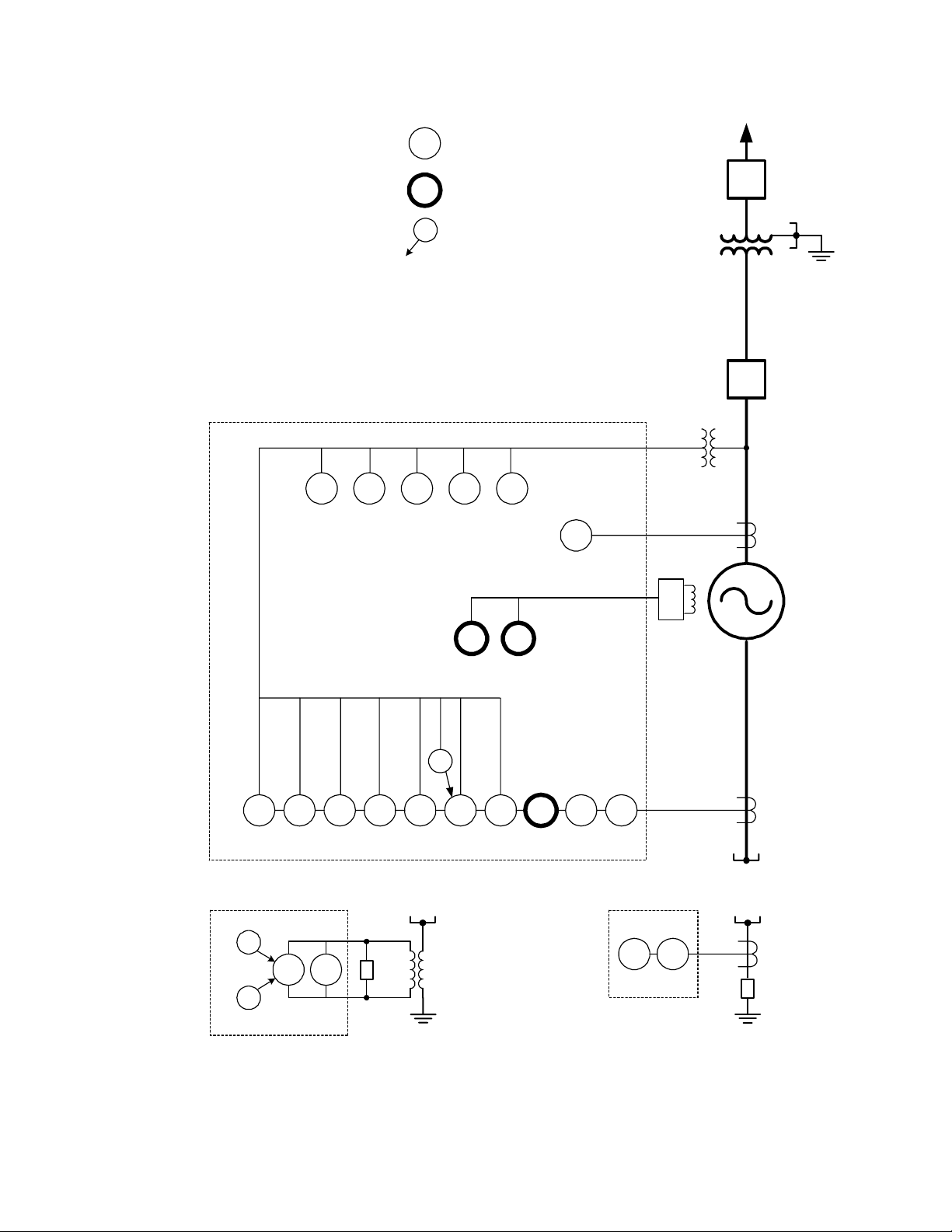
M-3425 Generator Protection Relay
50
DT
Utility System
52
Unit
52
Gen
5050/2740 51T 4651V60FL 21 78 32
27
81R 81 27 59 24
64F 64B
M-3921+
-
CT
VT
CT
M-3425
50N 51N
R
CT
VT
59N
27
TN
27
32
R
M-3425 M-3425
High-impedance Grounding with Third
Harmonic 100% Ground Fault Protection Low-impedance Grounding with
Overcurrent Stator Ground Fault Protection
This function is available as a
standard protective function.
This function is available as a
optional protective function.
This function provides control for
the function to which it points.
NOTE: Some functions are
mutually exclusive; see
Instruction Book for details.
M-3425 Typical
Connection Diagram
(Configured for Split-Phase Differential)
Figure 3 Typical One-Line Connection Diagram (configured for split-phase diffential)

–16–
M-3425 Generator Protection Relay
Example of Control / Output Connections
+
-
61 11 10
60
16 15
52b 60FL
POWER
SUPPLY
SELF-TEST
FAILURE
ALARM
+
-
DC: 24 V
48 V
EXTERNAL INPUTS ALARM OUTPUTS
CONTROL
OUTPUTS
TRIP
ALARM
12 13
POWER
OK
STATUS
ALARM
VT FUSE LOSS
TRIP
52G
TRIP OUTPUT
OSCILLOGRAPH
RECORDER
INITIATE
BREAKER
FAILURE
INITIATE
M-3425
OR
DC: 110 V
125 V
220 V
250 V
AC: 110 V
120 V
230 V
240 V
62
63
UTILITY SYSTEM
A
B
C
48 49
46 47
Other
Relays M-3425
50 51
Generator
Other
Relays
52
G
en
ABC
ThreeVTWye-Wye
Connection
40
41
38
39
42
43
M-3425
OR
OR
45
44
High Impedance Grounding
M-3425
58 59
56 57
54 55
M-3425
57 56
55 54
M-3425
59 58
57 56
55 54
M-3425
59 58
OR OR
M-3425
53
52
ABC
ABC ABC
AB C
M-3921
Field Ground
Coupler
Module
10
11
52b
M-3425
OR
Low Impedance Grounding
M-3425
42
43
40
41
38
39
Two VT Open-Delta
Connection
ABC
40
41
38
39
42
43
M-3425
ThreeVTWye-Wye
Connection -
Ungrounded
ABC
Figure 4 M-3425 Typical Three-Line Connection Diagram
■NOTE: M-3425 current terminal polarity marks (•) indicate "entering" current direction when primary current
is "from" the generator. If CT connections differ from those shown, adjust input terminals.
✴NOTE: Wire to split phase differential CTs for use with 50DT split phase function.
–17–
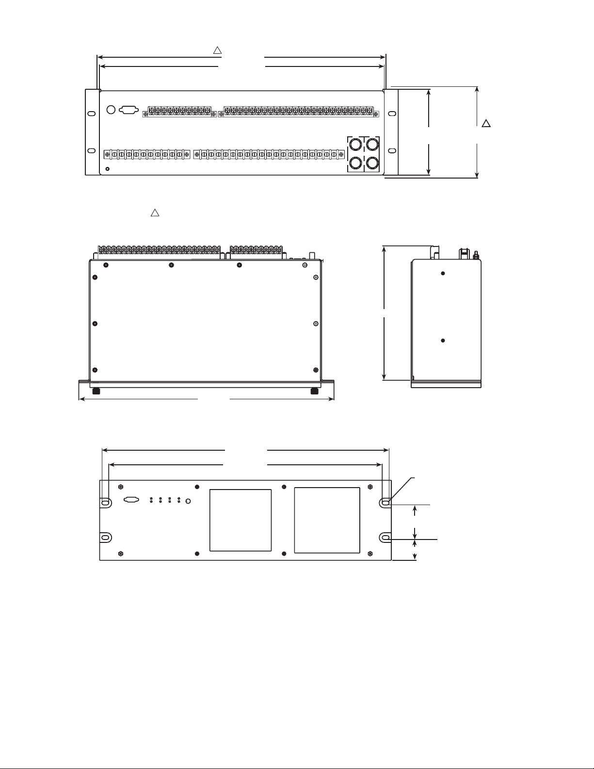
M-3425 Generator Protection Relay
17.31 [43.97]
ACTUAL
5.21 [13.23]
ACTUAL 5.28 [13.41]
17.45 [44.32]
10.20 [25.91]
19.00
[48.26]
17.78 [44.65]
18.58 [47.19]
2.35 [5.96]
1.35 [3.42]
Standard 19" Horizontal Mount Chassis
nNOTE: Dimensions in brackets are in centimeters.
RECOMMENDED CUTOUT WHEN RELAY IS
NOT USED AS STANDARD RACK MOUNT
Rear View
0.40 [1.02] x 0.27 [0.68] SLOT (4x)
Figure 5 Horizontal Mounting Dimensions
■NOTE: Panelsforvertical mounting are available. Whenmountedvertically, the target module will belocated
atthe top and all front-paneltext will be horizontally aligned. ConsultBeckwith Electric Co. for details.

–18–
M-3425 Generator Protection Relay
Optional Vertical Mount Chassis
nNOTE: Dimensions in brackets are
in centimeters.
17.78
[44.65]
18.58
[47.19]
2.25
[5.72] 1.71
[4.34]
19.00
[48.26]
17.31
[43.97]
Actual
5.59
[14.20]
5.65
[13.41]
17.45
[44.32]
ACTUAL
0.40 [1.02] x
0.27 [0.68]
SLOT (4x)
Rear View
RECOMMENDED CUTOUT WHEN RELAY IS
NOT USED AS STANDARD RACK MOUNT
Figure 6 Vertical Mounting Dimensions

–19–
M-3425 Generator Protection Relay
M-3921 Field Ground Coupler
■NOTES:
1. The above circuit measures insulation resistance (Rf) between rotor field winding and ground (64F).
2. Relay injects !15 V squarewave (Vout) and measures return signal (Vf) to calculate Rf.
3. Theinjection frequency can beset (0.1 to 1.0 Hz) based on the rotorcapacitance, in order toimprove
accuracy.
4. Analyzing signal rise time can determine if shaft brushes are open (64B).
Function Specification
Field/Exciter Supply Voltage Rating (Terminal (3) to (2)):
• 60 to 600 V dc, continuous
• 1000 V dc, 1 minute
Operating Temperature: –20° to +70°, Centigrade
Patent & Warranty
The M-3921 Field Ground Coupler is covered by a five year warranty from date of shipment.
Tests and Standards
M-3921Field Ground Coupler complies with the following tests and standards:
Voltage Withstand
Isolation
4 kV ac for 1 minute, all terminals to case
Impulse Voltage
IEC255–5, 5,000 V pk, 1.2 by 50 µs, 0.5 J, 3 positive and 3 negative impulses at 5 second
part 5 intervals per minute
Electrical Interference
Electrostatic Discharge Test
IEC 1000-4-2 Class 4 (8 kV)—point contact discharge
Fast Transient Disturbance Tests
IEC 1000-4-4 Class 4 (4 kV, 2.5 kHz)
Surge Withstand Capability
ANSI/IEEE 2,500 V pk-pk oscillatory applied to each independent circuit to earth
C37.90.1 2,500 V pk-pk applied between each independent circuit
5,000 V pk Fast Transient applied to each independent circuit to earth
5,000 V pk Fast Transient applied between each independent circuit
Radiated Susceptibility
ANSI/IEEE 25-1000 Mhz @ 20 V/m
C37.90.2
Atmospheric Environment
IEC 68–2–1 Cold, –20° C for 96 hours
IEC 68–2–2 Dry Heat, +70° C for 96 hours
IEC 68–2–3 Damp Heat, +40° C @ 93% RH, for 96 hours
Enclosure Protection
NEMA 1, IEC IPC-65
Table of contents
Other BECKWITH ELECTRIC Protection Device manuals


