BECKWITH ELECTRIC M-3425A User manual

Instruction Book
M-3425A
Generator Protection

Generator Protection
M‑3425A
Integrated Protection System
®
for Generators of All Sizes
PROTECTION
Unit shown with optional M‑3925A Target Module and M‑3931 HMI (Human‑Machine Interface) Module
• ExceedsIEEEC37.102andStandard242requirementsforgenerator
protection
• Protectsgeneratorsofanyprimemover,groundingandconnectiontype
• Providesallmajorprotectivefunctionsforgeneratorprotection
includingOut-of-Step(78),Split-PhaseDifferential(50DT),
UnderFrequencyTimeAccumulation(81A),Inadvertent
Energizing(50/27)andTurn-to-TurnFault(59X)
• ExpandedIPScom®CommunicationsSoftwareprovidessimpleand
logicalsettingandprogramming,includinglogicschemes
• SimpleapplicationwithBaseandComprehensiveprotectionpackages
• Loadencroachmentblindersandpowerswingblockingfor
systembackupprotection(21)toenhancesecurityduring
systemabnormalconditions
• Options:EthernetConnection,FieldGround/BrushLift-OffProtection
(64F/B),SyncCheck(25),100%StatorGroundFaultProtectionby
lowfrequencyinjection(64S)andExpandedI/O(15additionalOutput
Contactsand8additionalControl/StatusInputs)

–2–
M‑3425A Generator Protection Relay
Protective Functions
Comprehensive Package
TheComprehensivePackageincludesallBasePack-
age functions, as well as the following:
• Three‑zonePhaseDistanceprotectionfor
phase fault backup protection (21). Zone
three can be used for Out-of-Step Block-
ing. Load encroachment blinders can be
applied.
• 100% Stator Ground Fault protection us-
ing Third Harmonic Neutral Undervoltage
(27TN) or (59D) Third Harmonic Voltage
Differential(ratio)
• Stator Overload (49) (Positive Sequence
Overcurrent)
• DeniteTime Overcurrent(50DT)canbe
used for split phase differential
• Out‑of‑Step(78)
• UnderFrequencyAccumulation(81A)
• RateofChangeofFrequency(81R)
Optional Protective Functions
• SyncCheckwithPhaseAngle,∆Vand∆F
with dead line/dead bus options (25)
• FieldGround(64F)andBrushLiftOff(64B)
(IncludesM‑3921FieldGroundCoupler)
• 100% Stator Ground protection by low
frequency injection (64S). The following
equipmentisrequiredwiththe64Soption:
–20Hzsignalgenerator(430‑00426)
–Band‑passFilter(430‑00427)
–400/5A20HzCT(430‑00428)
Protective Functions
Base Package
• Overexcitation(V/Hz)(24)
• PhaseUndervoltage(27)
• Directional power sensitive triple‑setpoint
Reverse Power, Low Forward Power or
Overpower detection, one of which can be
usedforsequentialtripping(32)
• Dual‑zone,offset‑mhoLossofField(40),
which may be applied with undervoltage
controlled accelerated tripping
• SensitiveNegativeSequenceOvercurrent
protectionandalarm(46)
• InstantaneousPhaseOvercurrent(50)
• InadvertentEnergizing(50/27)
• GeneratorBreakerFailure(50BF)
• InstantaneousNeutralOvercurrent(50N)
• InverseTimeNeutralOvercurrent(51N)
• Three‑phase Inverse Time Overcurrent
(51V) with voltage control and voltage
restraint.
• PhaseOvervoltage(59)
• NeutralOvervoltage(59N)
• Multi‑purposeOvervoltage(59X)
• VT Fuse‑Loss Detection and blocking
(60FL)
• ResidualDirectionalOvercurrent(67N)
• Four‑stepOver/Underfrequency(81)
• Phase DifferentialCurrent(87)
• Ground (zero sequence) Differential
Current(87GD)
• IPSlogictakesthecontactinputstatusand
function status and generates outputs by
employing (OR, AND, and NOT) boolean
logic and a timer.

–3–
M‑3425A Generator Protection Relay
Standard Features
• Eight programmable outputs and six
programmable inputs
• OscillographicrecordingwithCOMTRADE
orBECOformat
• Time‑stampedtargetstoragefor32events
• Meteringofallmeasuredparametersand
calculated values
• Threecommunicationsports(twoRS‑232
andoneRS‑485)
• S‑3400IPScom®CommunicationsSoftware
• IncludesMODBUSandBECO2200proto-
cols
• Standard 19" rack‑mount design (vertical
mounting available)
• Removableprintedcircuitboardandpowersupply
• 50and60Hzmodelsavailable
• Both1Aand5AratedCTinputsavailable
• Additional trip inputs for externally con-
nected devices
• IRIG‑Btimesynchronization
• OperatingTemperature:–20°Cto+70°C
• SequenceofEventsLog
• TripCircuitMonitoring
• BreakerMonitoring
• FourSetpointGroups
Optional Features
• Redundantpowersupply
• M‑3925ATargetModule
• M‑3931 Human‑Machine Interface (HMI)
Module
• RJ45 Ethernet port utilizing MODBUS over
TCP/IPandBECO2200overTCP/IPpro-
tocols
• RJ45 Ethernet port utilizing IEC 61850
Protocol
• M‑3801D IPSplot®PLUS Oscillograph
AnalysisSoftware
• Expanded I/O (15 additional outputs and
8additionalinputs)
• StandardandExpandedI/OModelsavail-
able in vertical panel mount

–4–
M‑3425A Generator Protection Relay
PROTECTIVE FUNCTIONS
Device Setpoint
Number Function Ranges Increment Accuracy†
Phase Distance (three‑zone mho characteristic)
CircleDiameter#1,#2,#3 0.1to100.0Ω 0.1Ω0.1Ωor5%
(0.5to500.0Ω) (0.5Ωor5%)
Offset#1,#2,#3 –100.0to100.0Ω 0.1Ω0.1Ωor5%
(–500.0to500.0Ω) (0.5Ωor5%)
ImpedanceAngle#1,#2,#3 0°to90° 1° 1°
Load Encroachment Blinder #1,#2,#3
Angle 1°to90° 1° 1°
RReach 0.1to100Ω
TimeDelay#1,#2,#3 1to8160Cycles 1Cycle 1Cycleor1%
Out‑of‑StepDelay 1to8160Cycles 1Cycle 1Cycleor1%
OvercurrentSupervision 0.1to20A 0.1A 0.1Aor2%
(0.02to4A) 0.01A 0.02Aor2%
When out‑of‑step blocking on Zone 1 or Zone 2 is enabled, Zone 3 will not trip and it will be used to detect the out‑
of‑step condition for blocking Function 21 #1 and/or 21 #2.
Volts / Hz
DefiniteTime
Pickup#1,#2 100to200% 1% 1%
TimeDelay#1,#2 30to8160Cycles 1Cycle 25Cycles
InverseTime
Pickup 100to200% 1% 1%
CharacteristicCurves InverseTime#1–#4 — —
TimeDial: Curve#1 1to100 1 1%
TimeDial: Curves#2–#4 0.0to9.0 0.1 1%
ResetRate 1to999Sec. 1Sec. 1 Second or 1%
(from threshold of trip)
The percent pickup is based on nominalVT secondary voltage and nominal system frequency settings.The pickup
accuracy stated is only applicable from 10 to 80 Hz, 0 to 180 V, 100 to 150% V/Hz and a nominal voltage setting of
120V.
Phase Undervoltage
Pickup#1,#2,#3 5to180V 1V 0.5Vor0.5%
0.8Vor0.75%*
TimeDelay#1,#2,#3 1to8160Cycles 1Cycle 1Cycleor0.5%**
* When both RMS and Line‑Ground to Line‑Line VT connection is selected.
**When RMS (total waveform) is selected, timing accuracy is O20 cycles or 1%.
†Selectthegreateroftheseaccuracyvalues.
Valuesinparenthesesapplyto1ACTsecondaryrating.
21
24
27

–5–
M‑3425A Generator Protection Relay
PROTECTIVE FUNCTIONS (cont.)
Device Setpoint
Number Function Ranges Increment Accuracy†
Third‑Harmonic Undervoltage, Neutral
Pickup#1,#2 0.10to14.00V 0.01V 0.1Vor1%
PositiveSequence
VoltageBlock 5to180V 1V 0.5Vor0.5%
ForwardUnderPowerBlock 0.01to1.00PU 0.01PU 0.01PUor2%
ReverseUnderPowerBlock–1.00to–0.01PU 0.01PU 0.01PUor2%
LeadUnderVArBlock –1.00to–0.01PU 0.01PU 0.01PUor2%
LagUnderVArBlock 0.01to1.00PU 0.01PU 0.01PUor2%
LeadPowerFactorBlock 0.01to1.00 0.01 0.03PUor3%
LagPowerFactorBlock 0.01to1.00 0.01 0.03PUor3%
HighBandForward
PowerBlock 0.01to1.00PU 0.01PU 0.01PUor2%
LowBandForward
PowerBlock 0.01to1.00PU 0.01PU 0.01PUor2%
TimeDelay#1,#2 1to8160Cycles 1Cycle –1to+5Cyclesor1%
Directional Power
Pickup#1,#2,#3 –3.000to+3.000PU 0.001PU 0.002PUor2%
TimeDelay#1,#2,#3 1to8160Cycles 1Cycle +16Cyclesor1%
The minimum Pickup limits are –.002 and +.002 respectively.
The per‑unit pickup is based on nominalVT secondary voltage and nominal CT secondary current settings.This
function can be selected as either overpower or underpower in the forward direction (positive setting) or reverse
direction (negative setting).Element #3 can be set as real power or reactive power.This function includes a pro‑
grammable target LED that may be disabled.
Loss of Field (dual‑zone offset‑mho characteristic)
CircleDiameter#1,#2 0.1to100.0Ω 0.1Ω0.1Ωor 5%
(0.5to500.0Ω) (0.5Ωor 5%)
Offset#1,#2 –50.0to50.0Ω 0.1Ω0.1Ωor 5%
(–250.0to250.0Ω) (0.5Ωor 5%)
TimeDelay#1,#2 1to8160Cycles 1Cycle 1Cycleor1%
TimeDelaywith
VoltageControl#1,#2 1to8160Cycles 1Cycle 1Cycleor1%
VoltageControl 5to180V 1V 0.5Vor0.5%
(positivesequence)
DirectionalElement 0°to20° 1° —
Time delay with voltage control for each zone can be individually enabled.
†Selectthegreateroftheseaccuracyvalues.
Valuesinparenthesesapplyto1ACTsecondaryrating.
40
32
27
TN

–6–
M‑3425A Generator Protection Relay
PROTECTIVE FUNCTIONS (cont.)
Device Setpoint
Number Function Ranges Increment Accuracy†
Negative Sequence Overcurrent
DefiniteTime
Pickup 3to100% 1% 0.5%of5A
(0.5%of1A)
TimeDelay 1to8160Cycles 1Cycle 1 Cycleor1%
InverseTime
Pickup 3to100% 1% 0.5%of5A
(0.5%of1A)
TimeDialSetting 1to95 1 3Cyclesor3%
(K= I22t)
DeniteMaximum
TimetoTrip 600to65,500Cycles 1Cycle 1Cycleor1%
DeniteMinimumTime 12Cycles — xed
ResetTime(Linear) 1to600Seconds 1Second 1 Second or 1%
(from threshold of trip)
Pickup is based on the generator nominal current setting.
Stator Overload Protection
TimeConstant#1,#2 1.0to999.9minutes 0.1minutes
MaximumOverloadCurrent 1.00to10.00A 0.01A 0.1Aor2%
(0.20to2.00A)
Instantaneous Phase Overcurrent
Pickup#1,#2 0.1to240.0A 0.1A 0.1Aor3%
(0.1to48.0A) (0.02Aor3%)
TimeDelay#1,#2 1to8160Cycles 1Cycle 1Cycleor1%
When frequency f is < (fnom –5 ) Hz add an additional time of (1.5/f + 0.033) sec to the time delay accuracy.
Breaker Failure
Pickup
PhaseCurrent 0.10to10.00A 0.01A 0.1Aor2%
(0.02to2.00A) (0.02Aor2%)
NeutralCurrent 0.10to10.00A 0.01A 0.1Aor2%
(0.02to2.00A) (0.02Aor2%)
TimeDelay 1to8160Cycles 1Cycle 1Cycleor1%
50BF can be initiated from designated M‑3425A output contacts or programmable control/status inputs.
DefiniteTime Overcurrent
PickupPhaseA#1,#2 0.20Ato240.00A 0.01A 0.1Aor3%
(0.04Ato48.00A) (0.02Aor3%)
PickupPhaseB#1,#2 (sameasabove)
PickupPhaseC#1,#2 (sameasabove)
TimeDelay#1,#2 1to8160Cycles 1Cycle 1Cycleor1%
This function uses generator line‑side currents.
When 50DT function is used for split‑phase differential protection, 50BF, 87, and 87GD functions should not be
used, and the IA, IBand ICinputs must be connected to the split phase differential currents.
†Selectthegreateroftheseaccuracyvalues.
Valuesinparenthesesapplyto1ACTsecondaryrating.
50
DT
50
50
BF
50
BF‑Ph
50
BF‑N
46
49

–7–
M‑3425A Generator Protection Relay
PROTECTIVE FUNCTIONS (cont.)
Device Setpoint
Number Function Ranges Increment Accuracy†
Instantaneous Neutral Overcurrent
Pickup 0.1to240.0A 0.1A 0.1Aor3%
(0.1to48.0A) (0.02Aor3%)
TimeDelay 1to8160Cycles 1Cycle 1Cycleor1%
When the frequency f is < (fnom –5) Hz add an additional time of (1.5/f + 0.033) sec to the time delay accuracy.
Inadvertent Energizing
Overcurrent
Pickup 0.5to15.00A 0.01A 0.1Aor2%
(0.1to3.00A) (0.02Aor2%)
Undervoltage
Pickup 5to130V 1V 0.5V
Pick‑upTimeDelay 1to8160Cycles 1Cycle 1Cycleor1%
Drop‑outTimeDelay 1to8160Cycles 1Cycle 1Cycleor1%
When RMS (total Waveform) is selected, timing accuracy is O20 cycles or 1%.
InverseTime Neutral Overcurrent
Pickup 0.25to12.00A 0.01A 0.1Aor1%
(0.05to2.40A) (0.02Aor1%)
CharacteristicCurve DeniteTime/Inverse/VeryInverse/ExtremelyInverse/IECCurves
ModeratelyInverse/VeryInverse/ExtremelyInverse/IEEECurves
TimeDial 0.5to11.0 0.1 3Cyclesor3%*
0.05to1.10(IECcurves) 0.01
0.5to15.0(IEEEcurves) 0.01
* For IEC Curves the timing accuracy is 5%.
When the frequency f is < (fnom –5 )Hz add an additional time of (1.5/f + 0.033) sec to the time delay accuracy.
InverseTime Phase Overcurrent, withVoltage Control orVoltage Restraint
Pickup 0.50to12.00A 0.01A 0.1Aor1%
(0.10to2.40A) (0.02Aor1%)
CharacteristicCurve DeniteTime/Inverse/VeryInverse/ExtremelyInverse/IECCurves
ModeratelyInverse/VeryInverse/ExtremelyInverse/IEEECurves
TimeDial 0.5to11.0 0.1 3Cyclesor3%*
0.05to1.10(IECcurves) 0.01
0.5to15.0(IEEEcurves) 0.01
VoltageControl(VC) 5to180V 1V 0.5Vor0.5%
or
VoltageRestraint(VR) LinearRestraint ——
* For IEC Curves the timing accuracy is 5%.
51V
51N
50N
50/
27
50
27
†Selectthegreateroftheseaccuracyvalues.
Valuesinparenthesesapplyto1ACTsecondaryrating.

–8–
M‑3425A Generator Protection Relay
PROTECTIVE FUNCTIONS (cont.)
Device Setpoint
Number Function Ranges Increment Accuracy†
Phase Overvoltage
Pickup #1, #2, #3 5 to 180 V 1 V 0.5V or 0.5%
0.8 V or 0.75%*
Time Delay #1, #2, #3 1 to 8160 Cycles 1 Cycle 1 Cycle or 1%**
Input Voltage Select Phase, Positive or Negative Sequence***
* When both RMS and Line‑Ground to Line‑Line is selected.
** When RMS (total waveform) is selected, timing accuracy is O20 cycles or 1%.
*** When positive or negative sequence voltage is selected, the 59 Function uses the discrete Fourier transform
(DFT) for magnitude calculation, irrespective of the RMS/DFT selection, and timing accuracy is 1 Cycle or
1%. Positive and negative sequence voltages are calculated in terms of line‑to‑line voltage when Line to Line is
selected for V.T. Configuration.
Third-HarmonicVoltage Differential Ratio
Ratio (Vx/VN) 0.1 to 5.0 0.1
Time Delay 1 to 8160 Cycles 1 Cycle 1 Cycle or 1%
Positive Seq Voltage Block 5 to 180 V 1 V 0.5 V or 0.5%
Line Side Voltage VXor 3V0(calculated)
The 59D function has a cutoff voltage of 0.5V for 3rd harmonic VXvoltage.If the 180 Hz component of VNis
expected to be less than 0.5 V the 59D function can not be used.
The 59D function with VXcannot be enabled if the 25 function is enabled.The line side voltage can be selected as
the third harmonic of 3V0 (equivalent to VA+ VB+ VC) or VX.
3V0selection for line side voltage can only be used with line‑ground VT configuration.
Neutral Overvoltage
Pickup #1, #2, #3 5.0 to 180.0 V 0.1 V 0.5 V or 0.5%
Time Delay #1, #2, #3 1 to 8160 Cycles 1 Cycle 1 Cycle or 1%
When 64S is purchased, the 59N Time Delay Accuracy is –1 to +5 cycles.
Multi-purpose Overvoltage
Pickup #1, #2 5.0 to 180.0 V 0.1 V 0.5 V or 0.5%
Time Delay #1, #2 1 to 8160 Cycles 1 Cycle 1 Cycle or 1%
Multi‑purpose input that may be used for turn‑to‑turn stator ground protection, bus ground protection, or as an
extra Phase‑Phase, or Phase‑Ground voltage input.
When 64S is purchased, the 59N Time Delay accuracy is –1 to +5 cycles.
VT Fuse-Loss Detection
AVT fuse-loss condition is detected by using the positive and negative sequence components
of the voltages and currents.VT fuse-loss output can be initiated from internally generated logic,
and/or from input contacts.
Alarm Time Delay 1 to 8160 Cycles 1 Cycle 1 Cycle or 1%
Three Phase VT
Fuse Loss Detection Enable/Disable
59
59N
60
FL
59X
59D
†Select the greater of these accuracy values.
Values in parentheses apply to 1 A CT secondary rating.

–9–
M‑3425A Generator Protection Relay
PROTECTIVE FUNCTIONS (cont.)
Device Setpoint
Number Function Ranges Increment Accuracy†
Residual Directional Overcurrent
DefiniteTime*
Pickup 0.5to240.0A 0.1A 0.1Aor3%
(0.1to48.0A) (0.02Aor3%)
TimeDelay 1to8160Cycles 1Cycle –1to+3Cyclesor1%
InverseTime*
Pickup 0.25to12.00A 0.01A 0.1Aor3%
(0.05to2.40A) (0.02Aor3%)
CharacteristicCurve DeniteTime/Inverse/VeryInverse/ExtremelyInverse/IECCurves
ModeratelyInverse/VeryInverse/ExtremelyInverse/IEEECurves
TimeDial 0.5to11.0 0.1 3Cyclesor5%
0.05to1.10(IECCurves) 0.01
0.5to15.0(IEEEcurves) 0.01
Directional Element
MaxSensitivityAngle(MSA) 0to359° 1°
PolarizingQuantity 3Vo(calculated),VNorVX
*Directional control for 67NDT or 67NIT may be disabled.
VXpolarization cannot be used if 25 function is enabled.
3Vopolarization can only be used with line‑ground VT configuration.
Operating current for 67N can be selected as 3Io (calculated) or IN(Residual CT).
If 87GD is enabled, 67N with IN(Residual CT) operating current will not be available.
Out of Step (mho characteristic)
CircleDiameter 0.1to100.0Ω 0.1Ω0.1Ωor5%
(0.5to500.0Ω) (0.5Ωor5%)
Offset –100.0to100.0Ω 0.1Ω0.1Ωor5%
(–500.0to500.0Ω) (0.5Ωor5%)
ImpedanceAngle 0°to90° 1° 1°
Blinder 0.1to50.0Ω 0.1Ω0.1Ωor5%
(0.5to250.0Ω) (0.5Ωor5%)
TimeDelay 1to8160Cycles 1Cycle 1Cycleor1%
TriponmhoExit Enable/Disable
PoleSlipCounter 1to20 1
PoleSlipReset 1to8160Cycles 1Cycle 1Cycleor1%
Frequency
Pickup#1,#2,#3,#4 50.00to67.00Hz 0.01Hz 0.02Hz
40.00to57.00Hz*
TimeDelay#1–#4 3to65,500Cycles 1Cycle 2Cyclesor1%
The pickup accuracy applies to 60 Hz models at a range of 57 to 63 Hz, and to 50 Hz models at a range of 47 to
53 Hz. Beyond these ranges, the accuracy is 0.1 Hz.
* This range applies to 50 Hz nominal frequency models.
†Selectthegreateroftheseaccuracyvalues.
Valuesinparenthesesapplyto1ACTsecondaryrating.
81
78
67N

–10–
M‑3425A Generator Protection Relay
PROTECTIVE FUNCTIONS (cont.)
Device Setpoint
Number Function Ranges Increment Accuracy†
Frequency Accumulation
Bands#1,#2,#3,#4,#5,#6
HighBand#1 50.00to67.00Hz 0.01Hz 0.02Hz
40.00to57.00Hz*
LowBand#1–#6 50.00to67.00Hz 0.01Hz 0.02Hz
40.00to57.00Hz*
Delay#1–#6 3to360,000Cycles 1Cycle 2Cyclesor1%
When using multiple frequency bands, the lower limit of the previous band becomes the upper limit for the next band,
i.e., Low Band #2 is the upper limit for Band #3, and so forth. Frequency bands must be used in sequential order, 1 to 6.
Band #1 must be enabled to use Bands #2–#6. If any band is disabled, all following bands are disabled.
When frequency is within an enabled band limit, accumulation time starts (there is an internal ten cycle delay prior to
accumulation) and allows the underfrequency blade resonance to be established to avoid unnecessary accumulation of
time.When duration is greater than set delay, the alarm asserts and a target log entry is made.
The pickup accuracy applies to 60 Hz models at a range of 57 to 63 Hz, and 50 Hz models at a range of 47 to 53 Hz.
Beyond these ranges, the accuracy is 0.1 Hz.
* This range applies to 50 Hz nominal frequency models.
Rate of Change of Frequency
Pickup#1,#2 0.10to20.00Hz/Sec. 0.01Hz/Sec. 0.05Hz/Sec.or5%
TimeDelay#1,#2 3to8160Cycles 1Cycle +20Cycles
NegativeSequence
VoltageInhibit 0to99% 1% 0.5%
Phase Differential Current
Pickup#1,#2 0.20Ato3.00A 0.01A 0.1Aor5%
(0.04to0.60A)
(0.02Aor5%)
PercentSlope#1,#2 1to100% 1% 2%
TimeDelay*#1,#2 1to8160Cycles 1Cycle 1Cycleor1%
CTCorrection** 0.50to2.00 0.01
*When a time delay of 1 cycle is selected, the response time is less than 1–1/2 cycles.
**The CT Correction factor is multiplied by IA,IB,IC.
Ground (zero sequence) Differential Current
Pickup 0.20to10.00A 0.01A 0.1Aor5%
(0.04to2.00A) (0.02Aor5%)
TimeDelay 1to8160Cycles* 1Cycle +1to‑2Cyclesor1%
CTRatioCorrection(RC) 0.10to7.99 0.01
*The Time Delay Setting should not be less than 2 Cycles.
The 87GD function is provided primarily for low‑impedance grounded generator applications. This function oper‑
ates as a directional differential. If 3I0 or In is extremely small (less than 0.2 secondary Amps), the element be‑
comes non‑directional.
If 67N function with IN(Residual) operating current is enabled, 87GD will not be available.Also, if 50DT is used for
split‑phase differential, 87GD function will not be available.
†Selectthegreateroftheseaccuracyvalues.
Valuesinparenthesesapplyto1ACTsecondaryrating.
87
87
GD
81R
81A

–11–
M‑3425A Generator Protection Relay
PROTECTIVE FUNCTIONS (cont.)
Device Setpoint
Number Function Ranges Increment Accuracy†
IPSlogicTM
IPSlogic uses element pickups, element trip commands, control/status input state changes,
output contact close signals to develop 6 programmable logic schemes.
TimeDelay#1–#6 1to8160Cycles 1Cycle 1Cycleor1%
Breaker Monitoring
Pickup 0to50,000kACycles 1kACycles 1kACycles
orkA2Cycles orkA2Cycles orkA2Cycles
TimeDelay 0.1to4095.9Cycles 0.1Cycles 1Cycleor1%
Timing Method IT or I2T
PresetAccumulators 0to50,000kACycles 1kACycle
PhaseA,B,C
The Breaker Monitor feature calculates an estimate of the per‑phase wear on the breaker contacts by measuring
and integrating the current (or current squared) through the breaker contacts as an arc.
The per‑phase values are added to an accumulated total for each phase, and then compared to a user‑pro‑
grammed threshold value.When the threshold is exceeded in any phase, the relay can set a programmable output
contact.
The accumulated value for each phase can be displayed.
The Breaker Monitoring feature requires an initiating contact to begin accumulation, and the accumulation begins
after the set time delay.
Trip Circuit Monitoring
TimeDelay 1to8160Cycles 1Cycle 1Cycleor1%
The AUX input is provided for monitoring the integrity of the trip circuit.This input can be used for nominal trip coil
voltages of 24V dc, 48 V dc, 125 V dc and 250 V dc.
Nominal Settings
NominalVoltage 50.0to140.0V 0.1V —
NominalCurrent 0.50to6.00A 0.01A —
VTConguration Line‑Line/Line‑Ground/
Line‑GroundtoLine‑Line*
Delta/WyeUnit
Transformer Disable/DeltaAB/DeltaAC
Seal‑InDelay 2to8160Cycles 1Cycle 1Cycleor1%
*When Line‑Ground to Line‑Line is selected, the relay internally calculates the line‑line voltages from the line‑
ground voltages for all voltage‑sensitive functions.This Line‑Ground to Line‑Line selection should only be used for
a VT connected Line‑Ground with a secondary voltage of 69 V (not 120 V).
†Selectthegreateroftheseaccuracyvalues.
Valuesinparenthesesapplyto1ACTsecondaryrating.
IPS
BM
TC

–12–
M‑3425A Generator Protection Relay
64F
64B
25
25S
25D
64S
OPTIONAL PROTECTIVE FUNCTIONS
Device Setpoint
Number Function Ranges Increment Accuracy†
Sync Check
Dead Check
Dead Voltage Limit 0 to 60 V 1 V 0.5 V or ±0.5%
Dead Time Delay 1 to 8160 Cycles 1 Cycle –1 to +3 Cycles or 1%
Sync Check
Phase Angle Limit 0° to 90° 1° 1°
Upper Voltage Limit 60 to 140 V 1 V 0.5 V or ±0.5%
Lower Voltage Limit 40 to 120 V 1 V 0.5 V or ±0.5%
Delta Voltage Limit 1.0 to 50.0 V 0.1 V 0.5 V or ±0.5%
Delta Frequency Limit 0.001 to 0.500 Hz 0.001 Hz 0.0007 Hz or ±5%
Sync CheckTime Delay 1 to 8160 Cycles 1 Cycle –1 to +3 Cycles or ±1%
Various combinations of input supervised hot/dead closing schemes may be selected.The 25 function cannot be
enabled if the 59D function withVXor 67N function with VXis enabled.
Field Ground Protection
Pickup #1, #2 5 to 100 KΩ1 KΩ10% or ±1KΩ
Time Delay #1, #2 1 to 8160 Cycles 1 Cycle (2
IF +1) Sec.
Injection Frequency (IF) 0.10 to 1.00 Hz 0.01 Hz
Brush Lift-Off Detection (measuring control circuit)
Pickup 0 to 5000 mV 1 mV
Time Delay 1 to 8160 Cycles 1 Cycle (2
IF +1) Sec.
When 64F is purchased, an external Coupler Module (M‑3921) is provided for isolation from dc field voltages.
Figure 10, Field Ground Protection Block Diagram, illustrates a typical connection utilizing the M‑3921 Field
Ground Coupler. Hardware dimensional and mounting information is shown in Figure 11, M‑3921 Field Ground
Coupler Mounting Dimensions.
100% Stator Ground Protection by low frequency injection
Total Current Pickup 2 to 75 mA 0.1 mA 2 mA or 10%
Real Component of
Total Current Pickup** 2 to 75 mA 0.1 mA 2 mA or 10%
Time Delay 1 to 8160 Cycles 1 Cycle 1 Cycle* or 1%
An external Low Frequency Generator, Band Pass Filter and Current Transformer are required for this function.
Figure 13, 64S Function Component Connection Diagram, illustrates a typical 100% Stator Ground Protection by
Low Frequency Injection application. Hardware dimensional and mounting information is illustrated in Figures 14
and 15.
59D is automatically disabled when the 64S function is purchased.59N may be applied when this function is
enabled.
* Time Delay accuracy in cycles is based on 20 Hz frequency.
** Operation of the real component requires voltage applied to VNinput to be > 0.5 Volts at 20 Hz.
†Select the greater of these accuracy values.
Values in parentheses apply to 1 A CT secondary rating.

–13–
M‑3425A Generator Protection Relay
Description
TheM‑3425AGeneratorProtectionRelayissuitableforallgeneratorratingsandprimemovers.Typicalcon-
nectiondiagramsareillustrated in Figure4, M‑3425A One‑LineFunctional Diagram(conguredforphase
differential),andFigure5,One‑LineFunctionalDiagram(conguredforsplit‑phasedifferential).
Configuration Options
TheM‑3425AGeneratorProtectionRelayisavailableineitheraBaseorComprehensivepackageofprotec-
tivefunctions.Thisprovidestheuserwithexibilityinselectingaprotectivesystemtobestsuittheapplication.
AdditionalOptionalProtectiveFunctionsmaybeaddedatthetimeofpurchaseatper‑functionpricing.
TheHuman‑MachineInterface(HMI)Module,TargetModule,orredundantpowersupplycanbeselectedat
time of purchase.
WhentheFieldGround(64F)PremiumProtectiveFunctionispurchased,anexternalcouplermodule(M‑3921)
isprovidedforisolationfromthedceldvoltages.
When100%StatorGround(64S)protectionusinglow‑frequencyinjectionispurchased,anexternalbandpass
lterandfrequencygeneratorisprovided.
Multiple Setpoint Profiles (Groups)
Therelaysupportsfoursetpointproles.Thisfeatureallowsmultiplesetpointprolestobedenedfordifferent
powersystemcongurationsorgeneratoroperatingmodes.Prolescanbeswitchedeithermanuallyusingthe
Human‑MachineInterface(HMI),bycommunications,programmablelogicorbycontrol/statusinputs.
NOTE: Duringproleswitching,relayoperationisdisabledforapproximately1second.
Metering
Therelayprovidesmeteringofvoltages(phase,neutralandsequencequantities),currents(phase,neutraland
sequencequantities),realpower,reactivepower,powerfactorandimpedancemeasurements.
Metering accuracies are:
Voltage: 0.5Vor0.5%,whicheverisgreater
0.8Vor0.75%,whicheverisgreater(whenbothRMSandLine‑GroundtoLine‑Lineare
selected)
Current: 5Arating,0.1Aor3%,whicheverisgreater
1Arating,0.02Aor3%,whicheverisgreater
Power: 0.01PUor2%ofVAapplied,whicheverisgreater
Frequency: 0.02Hz(from57to63Hzfor60Hzmodels;from47to53Hzfor50Hzmodels)
0.1Hzbeyond63Hzfor60Hzmodels,andbeyond53Hzfor50Hzmodels
Volts/Hz: 1%
Oscillographic Recorder
The oscillographic recorder provides comprehensive data recording of all monitored waveforms, storing up to
416cyclesofdata.Thetotalrecordlengthisuser‑congurablefrom1to16partitions.Thesamplingrateis
16timesthepowersystemnominalfrequency(50or60Hz).Therecordermaybetriggeredusingeitherthe
designatedcontrol/statusinputs,tripoutputs,orusingserialcommunications.Whenuntriggered,therecorder
continuouslystoreswaveformdata,therebykeepingthemost recent data inmemory.Whentriggered,the
recorderstorespre‑triggerdata,thencontinuestostoredatainmemoryforauser‑dened,post‑triggerdelay
period.ThedatarecordscanbestoredineitherBeckwithElectricformatorCOMTRADE format. Oscillograph
recordsarenotretainedifpowertotherelayisinterrupted.
Target Storage
Information associated with the last 32 trips is stored. The information includes the function(s) operated, the
functions picked up, input/output status, time stamp, and phase and neutral currents at the time of trip.

–14–
M‑3425A Generator Protection Relay
Sequence of Events Log
TheSequenceofEventsLogrecordsrelayelementstatus,I/Ostatus,measuredvaluesandcalculatedvalues
timestampedwith1msresolutionatuser‑denedevents.TheSequenceofEventsLogincludes512ofthe
mostrecentlyrecordedrelayevents.Theeventsandtheassociateddataisavailableforviewingutilizingthe
S‑3400IPScomCommunicationsSoftware.SequenceofEventsrecordsarenotretainedifpowertotherelay
is interrupted.
Calculations
Current andVoltage RMSValues: UsesDiscreteFourierTransformalgorithmonsampledvoltageandcurrent
signalstoextractfundamentalfrequencyphasorsforrelaycalculations. RMScalculationforthe50,51N,59
and27functions,andthe24functionareobtainedusingthetimedomainapproachtoobtainaccuracyovera
widefrequencyband.WhentheRMSoptionisselected,themagnitudecalculationfor59and27functionsis
accurateoverawidefrequencyrange(10to80Hz).WhentheDFToptionisselected,themagnitudecalcula-
tionisaccuratenearnominalfrequency(50Hz/60Hz)butwilldegradeoutsidethenominalfrequency.For50
and51NfunctionstheDFTisusedwhenthefrequencyis55Hzto65Hzfor60Hz(nominal)and45Hzto
55Hzfor50Hz(nominal),outsideofthisrangeRMScalculationisused.
Power Input Options
Nominal110/120/230/240Vac,50/60Hz,ornominal110/125/220/250Vdc.Operatesproperlyfrom85Vac
to265Vacandfrom80Vdcto312.5Vdc.Withstands300Vacor315Vdcfor1second.Nominalburden
40VAat120Vac/125Vdc.
Nominal24/48Vdc,operatesproperlyfrom18Vdcto56Vdc,withstands65Vdcfor1second.Burden25
VAat24Vdcand30VAat48Vdc.
AnoptionalredundantpowersupplyisavailableforunitsthatarepurchasedwithouttheexpandedI/O.
ForthoseunitspurchasedwiththeexpandedI/O,theunitincludestwopowersupplieswhicharerequiredto
powertherelay.Burden(nominal)46VA@120Vac.
Sensing Inputs
Five Voltage Inputs: Ratedforanominalvoltageof50Vacto140Vacat60Hzor50Hz.Willwithstand240V
continuousvoltageand360Vfor10seconds.Sourcevoltagesmaybeline‑to‑groundorline‑to‑lineconnected.
PhasesequenceABCorACBissoftwareselectable.Voltagetransformerburdenlessthan0.2VAat120Vac.
Seven Current Inputs: Ratednominal current (IR)of 5.0 Aor 1.0 A at 60Hz or 50Hz. Will withstand3IR
continuouscurrentand100IRfor1second.Currenttransformerburdenislessthan0.5VAat5A,or0.3VA
at1A.
Control/Status Inputs
Thecontrol/statusinputs,INPUT1throughINPUT6,canbeprogrammedtoblockanyrelayprotectivefunction,
to trigger the oscillograph recorder, to operate one or more outputs or can be an input into IPSlogic.To provide
breakerstatusLEDindicationonthefrontpanel,theINPUT1control/statusinputcontactmustbeconnected
to the 52b breaker status contact.The minimum current value to initiate/pickup an Input is >25mA.
TheoptionalexpandedI/Oincludesanadditional8programmablecontrol/statusinputs(INPUT7throughINPUT14).
▲CAUTION:Thecontrol/statusinputsshouldbeconnectedtodrycontactsonly,andareinternallyconnected
(wetted)witha24Vdcpowersupply.
Output Contacts
Anyofthefunctionscanbeindividuallyprogrammedtoactivateanyoneormoreoftheeightprogrammable
outputcontactsOUTPUT1throughOUTPUT8.Anyoutputcontactcanalsobeselectedaspulsedorlatched.
IPSlogic can also be used to activate an output contact.
TheoptionalexpandedI/Oincludesanadditional15programmableoutputcontacts(OUTPUT9throughOUT-
PUT23).ThesecontactsarecongurableonlyusingIPScomsoftware.
Theeightoutputcontacts(sixform‘a’andtwoform‘c’),thepowersupplyalarmoutputcontact(form‘b’),the
self‑testalarmoutputcontact(form‘c’)andtheoptional15expandedI/Ooutputcontacts(form'a')areallrated
perANSI/IEEEC37.90‑1989fortripping.Make30Afor0.2seconds,carry8A,break6Aat120Vac,break
0.5Aat48Vdc;0.3A,125Vdc;0.2A,250VdcwithL/R=40mSec.

–15–
M‑3425A Generator Protection Relay
IPSlogic
ThisfeaturecanbeprogrammedutilizingtheIPScom®Communications Software. IPSlogic takes the contact
inputstatusandfunctionstatus,andbyemploying(OR,AND,andNOT)booleanlogicandatimer,canactivate
anoutputorchangesettingproles.
Target/Status Indicators and Controls
TheRELAY OK LEDrevealspropercyclingofthemicrocomputer.TheBRKR CLOSEDLEDwillilluminatewhen
the breaker is closed (when the 52b contact input is open).The OSC TRIGLEDindicatesthatoscillographic
datahasbeenrecordedintheunit'smemory.TheTARGETLEDwillilluminatewhenanyoftherelayfunctions
operate.Pressing and releasing the TARGET RESETbuttonresetsthetargetLEDiftheconditionscausingthe
operation have been removed.Holding the TARGET RESETpushbuttondisplaysthepresentpickupstatusof
therelayfunctions.ThePS1 and PS2LEDswillremainilluminatedaslongaspowerisappliedtotheunitand
thepowersupplyisoperatingproperly.TIME SYNCLEDilluminateswhenvalidIRIG‑Bsignalisappliedand
timesynchronizationhasbeenestablished.
Communication
CommunicationsportsincluderearpanelRS‑232andRS‑485ports,afrontpanelRS‑232port,arear‑panel
IRIG‑BportandanEthernetport(optional).Thecommunicationsprotocolimplementsserial,byte‑oriented,
asynchronous communication, providing the following functions when used with theWindows™-compatible
S‑3400IPScom®Communications Software. MODBUSandBECO2200protocolsaresupportedproviding:
• Interrogationandmodicationofsetpoints
• Time‑stampedinformationforthe32mostrecenttrips
• Real‑timemeteringofallquantitiesmeasured
• DownloadingofrecordedoscillographicdataandSequenceofEventsRecorderdata.
TheoptionalEthernetportcanbepurchasedwithMODBUSoverTCP/IPandBECO2200overTCP/IPprotocols
orwiththeIEC61850protocol.
IRIG‑B
TheM‑3425AGeneratorProtectionRelaycanaccepteithermodulatedordemodulatedIRIG‑Btimeclocksyn-
chronizationsignal.TheIRIG‑Btimesynchronizationinformationisusedtocorrectthehour,minutes,seconds,
and milliseconds information.
HMI Module (optional)
Local access to the relay is provided through an optional M‑3931 HMI (Human‑Machine Interface) Mod-
ule, allowing for easy‑to‑use, menu‑driven access to all functions utilizing six pushbuttons and a 2‑line by
24characteralphanumericvacuumorescentdisplay.FeaturesoftheHMIModuleinclude:
• User‑denableaccesscodesthatallowthreelevelsofsecurity
• Interrogationandmodicationofsetpoints
• Time‑stampedinformationforthe32mostrecenttrips
• Real‑timemeteringofallquantitiesmeasured
Target Module (optional)
AnoptionalM‑3925ATargetModuleprovides24targetand8outputLEDs.AppropriatetargetLEDswillillumi-
natewhenthe corresponding function operates.The targets can be reset with the TARGET RESET pushbutton.
The OUTPUTLEDsindicatethestatusoftheprogrammableoutputrelays.
–16–
M‑3425A Generator Protection Relay
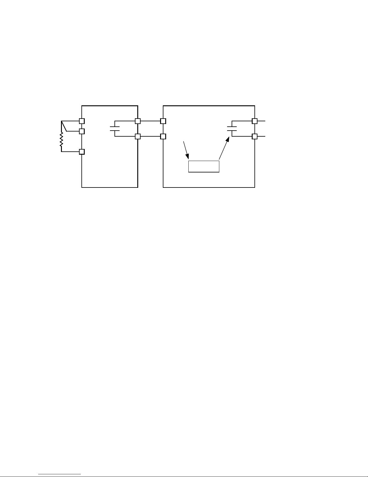
Temperature Controller Monitoring
AnyTemperatureControllerequippedwithacontactoutputmaybeconnectedtotheM‑3425Aandcontrolled
by the relay's programmable IPSlogic function. Figure 1 is an example of a typicalTemperature Control-
ler Monitoring application. The Omron E5C2Temperature Controller is a DIN rail mounted RTD interface
totheM‑3425AGeneratorProtection relay.TheE5C2 accepts type J or K thermocouples,platinumRTDs
orthermistors as its input.SupplyvoltagefortheE5C2accepts110/120Vac,50/60Hz,or220/240Vac
50/60Hzor24Vdc.
Temperature
Controller
Omron E5C2
P.D. 750
or equivalent
IN X
IN RTN
M-3425A
IPSlogic
Alarm/Trip
R1
C
R2
Figure 1 Typical Temperature Controller Monitoring Application
I/O Expansion (optional)
OptionalI/OExpansionprovidesanadditional15form'a'outputcontactsandanadditional8control/status
inputs.OutputLEDsindicatethestatusoftheoutputrelays.
Tests and Standards
Therelaycomplieswiththefollowingtypetestsandstandards:
Voltage Withstand
DielectricWithstand
IEC60255‑5 3,500Vdcfor1minuteappliedtoeachindependentcircuittoearth
3,500Vdcfor1minuteappliedbetweeneachindependentcircuit
1,500Vdcfor1minuteappliedtoIRIG‑Bcircuittoearth
1,500Vdcfor1minuteappliedbetweenIRIG‑Btoeachindependentcircuit
1,500Vdcfor1minuteappliedbetweenRS‑485toeachindependentcircuit
ImpulseVoltage
IEC60255‑5 5,000Vpk,+/‑polarityappliedtoeachindependentcircuittoearth
5,000Vpk,+/‑polarityappliedbetweeneachindependentcircuit
1.2by50µs,500ohmsimpedance,threesurgesat1every5seconds
Insulation Resistance
IEC60255‑5 >100Megaohms

–17–
M‑3425A Generator Protection Relay
Electrical Environment
Electrostatic DischargeTest
EN60255‑22‑2 Class4(8kV)—pointcontactdischarge
EN60255‑22‑2 Class4(15kV)–airdischarge
FastTransient Disturbance Test
EN60255‑22‑4 ClassA(4kV,2.5kHz)
SurgeWithstand Capability
ANSI/IEEE 2,500Vpk‑pkoscillatoryappliedtoeachindependentcircuittoearth
C37.90.1‑ 2,500Vpk‑pkoscillatoryappliedbetweeneachindependentcircuit
1989 5,000VpkFastTransientappliedtoeachindependentcircuittoearth
5,000VpkFastTransientappliedbetweeneachindependentcircuit
ANSI/IEEE 2,500Vpk‑pkoscillatoryappliedtoeachindependentcircuittoearth
C37.90.1‑ 2,500Vpk‑pkoscillatoryappliedbetweeneachindependentcircuit
2002 4,000VpkFastTransientburstappliedtoeachindependentcircuittoearth
4,000VpkFastTransientburstappliedbetweeneachindependentcircuit
NOTE: Thesignalisappliedtothedigitaldatacircuits(RS‑232,RS‑485,IRIG‑B,Ethernetcommunication
portandeldgroundcouplingport)throughcapacitivecouplingclamp.
Radiated Susceptibility
ANSI/IEEE 25‑1000Mhz@35V/m
C37.90.2
Output Contacts
ANSI/IEEE Make30Afor0.2seconds,offfor15secondsfor2,000operations,perSection6.7.1,Tripping
C37.90.0 OutputPerformanceRequirements
Atmospheric Environment
Temperature
IEC60068‑2‑1 Cold, –20°C
IEC60068‑2‑2 DryHeat,+70°C
IEC60068‑2‑3 DampHeat,+40°C@93%RH
Mechanical Environment
Vibration
IEC60255‑21‑1 VibrationresponseClass1,0.5g
VibrationenduranceClass1,1.0g
IEC60255‑21‑2ShockResponseClass1,5.0g
ShockWithstandClass1,15.0g
BumpEnduranceClass1,10.0g

–18–
M‑3425A Generator Protection Relay
Compliance
UL‑Listedper508 – IndustrialControlEquipment
UL‑ListedComponentper508ATableSA1.1IndustrialControlPanels
CSA‑CertiedperC22.2No.14‑95 – IndustrialControlEquipment
CESafetyDirective–EN61010‑1:2001,CATII,PollutionDegree2
Physical
Without Optional Expanded I/O
Size: 19.00"widex5.21"highx10.20"deep(48.3cmx13.2cmx25.9cm)
Mounting: Theunitisastandard19",semiush,three‑unithigh,rack‑mountpaneldesign,conformingtoANSI/
EIARS‑310CandDIN41494Part5specications.Verticalorhorizontalpanel‑mountoptionsareavailable.
Approximate Weight: 17 lbs (7.7 kg)
Approximate Shipping Weight: 25 lbs (11.3 kg)
With Optional Expanded I/O
Size: 19.00"widex6.96"highx10.2"deep(48.3cmx17.7cmx25.9cm)
Mounting: Theunitisastandard19",semiush,four‑unithigh,rack‑mountpaneldesign,conformingtoANSI/
EIARS‑310CandDIN41494Part5specications.Verticalorhorizontalpanel‑mountoptionsareavailable.
Approximate Weight: 19lbs(8.6kg)
Approximate Shipping Weight: 26lbs(11.8kg)
Recommended Storage Parameters
Temperature: 5°Cto40°C
Humidity:Maximumrelativehumidity80%fortemperaturesupto31°C,decreasingto31°Clin-
earlyto50%relativehumidityat40°C.
Environment: Storage area to be free of dust, corrosive gases, flammable materials, dew,
percolating water, rain and solar radiation.
See M‑3425A Instruction Book, Appendix E, Layup and Storage for additional information.
Patent & Warranty
TheM‑3425AGeneratorProtectionRelayiscoveredbyU.S.Patents5,592,393and5,224,011.
TheM‑3425AGeneratorProtectionRelayiscoveredbyaveyearwarrantyfromdateofshipment.
Specification subject to change without notice.
External Connections
M‑3425AexternalconnectionpointsareillustratedinFigures2and3.

–19–
M‑3425A Generator Protection Relay
Figure 2 External Connections (Without Optional Expanded I/O)
NOTES:
1. SeeM‑3425AInstructionBookSection2.3,SetpointsandTimeSettings,subsectionfor64B/FFieldGroundProtection.
2. BeforemakingconnectionstotheTripCircuitMonitoringinput,seeM‑3425AInstructionBookSection5.5,CircuitBoardSwitchesandJumpers,
fortheinformationregardingsettingTripCircuitMonitoringinputvoltage.Connectingavoltageotherthanthevoltagethattheunitiscongured
tomayresultinmis‑operationorpermanentdamagetotheunit.
3. 8WARNING:ONLY DRY CONTACTS must be connected to inputs (terminals 5 through 10 with 11 common) because these contact
inputs are internally wetted. Application of external voltage on these inputs may result in damage to the units.
4. 8WARNING:The protective grounding terminal must be connected to an earthed ground any time external connections have been
made to the unit.
Other manuals for M-3425A
2
Table of contents
Other BECKWITH ELECTRIC Protection Device manuals


