Becton Dickinson CLAY ADAMS CA6000 User manual

CLAY ADAMS™
CA6000
Centrifuge Users
Manual
BECTON DICKINSON AND COMPANY
Becton Dickinson Microbiology Systems
7 Lo eton Circle
Sparks, Maryland 21152 USA
18006318064
March, 1998
Document Number: MA0128
Re ision: New
Catalog Number: 42601025

CA6000 Centrifuge Users Manual
MA0128 ii
Clay Adams is a registered trademark of Becton Dickinson and Company.
© Copyright Becton Dickinson and Company 1998. All rights reserved. No part of this publication may be
reproduced transmitted transcribed stored in retrieval systems or translated into any language or
computer language in any form or by any means electronic mechanical magnetic optical chemical
manual or otherwise without the prior written permission of Becton Dickinson Microbiology Systems 7
Loveton Circle Sparks Maryland 21152 United States of America.

CA6000 Centrifuge Users Manual
MA0128 iii
Contents
1 Introduction
1.1 Overview Functional Principles ....................................................................................... 1
1.2 Safety Devices and Notices .............................................................................................. 3
1.3 Hazards Precautions and Limitations of Use ................................................................... 3
1.4 Rotor and Accessory Precautions ..................................................................................... 4
1.4.1 Corrosion Information ........................................................................................... 4
1.5 Contamination Hazards ..................................................................................................... 5
1.6 Manual Structure ............................................................................................................... 6
1.7 Use of this Manual ............................................................................................................ 6
1.8 Manual Conventions .......................................................................................................... 6
1.8.1 Symbols Used on the Equipment ......................................................................... 6
1.8.2 Notes Cautions and Warnings ............................................................................ 7
2 Installation and Setup
2.1 Transport Packaging Lifting ............................................................................................. 8
2.2 Installation ........................................................................................................................ 8
2.2.1 General Placement .............................................................................................. 8
2.2.2 Inspection ............................................................................................................ 9
2.2.3 Electrical Connection ........................................................................................... 9
2.2.4 Lid Unlock ............................................................................................................ 9
2.2.5 Assembly of the Rotating Head ............................................................................ 9
2.3 Specifications ................................................................................................................. 10
3 Controls and Indicators
3.1 General ........................................................................................................................... 12
3.2 On/Off Switch ................................................................................................................. 12
3.3 Lid Release Latch ........................................................................................................... 13
3.4 Emergency Lid Release Access Screw ........................................................................... 13
3.5 CA6000 Keypad .............................................................................................................. 13
3.5.1 RPM Readout .................................................................................................... 13
3.5.2 RPM Set Keys ................................................................................................... 13
3.5.3 Not In Use Indicator ........................................................................................... 14
3.5.4 In Use Indicator .................................................................................................. 14
3.5.5 Time (MIN) Readout ........................................................................................... 14
3.5.6 Time Set keys ................................................................................................... 14
3.5.7 SOFT ACCEL Key ............................................................................................. 14
3.5.8 SOFT ACCEL Indicator ...................................................................................... 14
3.5.9 SOFT BRAKE Key............................................................................................. 15
3.5.10 SOFT BRAKE Indicator ...................................................................................... 15
3.5.11 START key ......................................................................................................... 15
3.5.11 STOP/PROGRAM LOCK Key ............................................................................ 15
3.5.12 PROGRAM Keys ............................................................................................... 15
3.5.13 Program Indicators ............................................................................................. 15

CA6000 Centrifuge Users Manual
MA0128 i
Contents
4 Operation
4.1 CA6000 Centrifuge Setup for Operation ........................................................................... 16
4.2 Loading Balance ............................................................................................................. 17
4.3 Rotating Equipment Performance .................................................................................... 18
4.4 Selecting Operating Modes ............................................................................................. 18
4.5 Starting the Centrifuge ..................................................................................................... 20
4.6 Stopping the Centrifuge ................................................................................................... 20
4.7 Emergency Lid Unlock .................................................................................................... 20
5 Maintenance
5.1 Disassembly of the Rotating Head .................................................................................. 21
5.2 Rotating Equipment and Centrifugation Chamber Cleaning .............................................. 21
5.3 Exterior Cleaning ............................................................................................................ 22
5.4 Disinfection ..................................................................................................................... 22
5.5 Radioactive Decontamination .......................................................................................... 23
5.6 Fuses ............................................................................................................................. 23
6 Troubleshooting
6.1 Alarm Messages ............................................................................................................. 24
6.2 Other Problems .............................................................................................................. 25
6.3 Repair ............................................................................................................................. 25
A imited Warranty
B Parts and Accessories
C International Contacts
D Exploded View Drawing

CA6000 Centrifuge Users Manual
MA0128
Figures
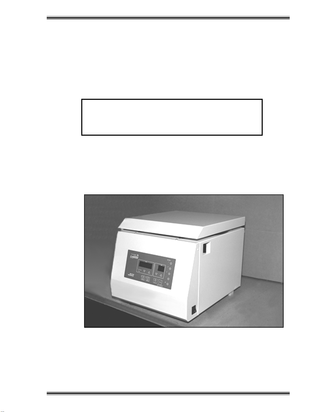
1 Clay Adams CA6000 Centrifuge ..................................................................................... 2
2 Symbols Used on the CA6000 Centrifuge ......................................................................... 6
3 CA6000 Centrifuge Layout .............................................................................................. 13
4 CA6000 Centrifuge Keypad ............................................................................................. 14
5 Loading Balance ............................................................................................................. 17
Tables
1 Physical Dimensions ...................................................................................................... 10
2 Environmental Requirements ........................................................................................... 10
3 Electrical Requirements ...................................................................................................11
4 Centrifugation Characteristics .......................................................................................... 11

MA0128 1
Introduction
1.1 Overview Functional Principles
The Clay Adams CA6000 centrifuge is a multipurpose centrifuge designed for laboratory use in
performing separation and sedimentation procedures. Through the application of a Relative Centrifugal
Force (RCF it allows the separation of substances made of different density elements. Potential
applications include hematology, chemistry, urinalysis, blood banking, microbiology, cytology, pharma-
cology, food processing, and agriculture.
Specific features include:
HMicroprocessor controlled
H5 Program (Memory Settings
HSpeeds from 300 6500 rpm in 10 rpm increments
HHigh or low acceleration (5 preprogrammed settings
HHigh or low deceleration (4 preprogrammed settings plus inertial
HTimer from 1 minute to 99 minutes plus infinite state
HElectronic-accelerometric imbalance encoder
HDirect drive system
HBrushless induction drive motor
CA6000 Centrifuge Users Manual
MA0128 2
Drive System
The centrifuge is driven by a three phase asynchronous motor. It is situated in the center of a sealed
and armor plated centrifugation chamber.
Safety Interlock System
The CA6000 centrifuge is equipped with an interlock system that prevents opening of the centrifuge lid
when the rotor is spinning. The centrifuge will not operate until the lid is closed and latched in place.
The lid remains latched until the rotor stops spinning.
NOTE
If a power failure occurs, you can access the samples in the centrifuge by
following the Emergency Lid Unlock procedure in Section 4.7.
Imbalance Sensor
The centrifuge is equipped with a load imbalance detector. In case of excessive imbalance the machine
stops and displays the message IMBAL. After the lid has been opened to remove the cause of the
imbalance, the message disappears. Carefully balance the sample load as described in Section 4.2
to avoid activating the imbalance detection system.
Figure 1 Clay Adams CA6000 Centrifuge

CA6000 Centrifuge Users Manual
MA0128 3
1.2 Safety Devices and Notices
In order to ensure both mechanical and electrical operational safety, the centrifuge features the following
safety control systems:
FThe centrifuge will not start unless the lid is locked. The lid cannot be opened while the rotor is
spinning, even in the event of power failure.
FSafety electronic circuits for self-diagnosis (with microprocessor control ; any possible breakdown
of the circuits and of the sensors is shown on the display and neutralized, preventing unsafe
operating conditions.
FLoad imbalance detection.
FDouble metal protection casing; reinforced centrifugation chamber in AISI 304 stainless steel.
FLid anti-fall mechanism.
FMain bipolar switch.
FNormalized filters to avoid Radio Frequency Interference (RFI .
FIndividual certified test, with measurements and testing of the leakage currents, the ground
resistance, and the applied voltage.
FIdentification plates; operating instructions.
1.3 Hazards, Precautions, and Limitations of Use
The following CAUTIONS and WARNINGS represent dangerous operations and work conditions to avoid.
!Using the centrifuge if it has not been properly installed.
!Leaning on the machine.
!Depositing any object in the free area of the centrifuge bowl.
!Using the centrifuge with rotating equipment showing evident corrosion, wear marks, or cracking
on the rotating head or on the buckets.
!Using the centrifuge with rotating equipment and accessories not approved by Becton Dickinson.
!Using the centrifuge in explosion risk rooms, or with explosion risk products or chemical materials
subject to violent reaction.
!Incorrect assembly of the rotating head on the driving stud.
!Imbalanced load causing an excessive vibration of the centrifuge.
!Failing to insert all buckets into the rotating equipment, even for partial loads.
!Moving or shifting the machine during centrifugation.
WARNING
IF AN DANGEROUS EVENT OCCURS INVOLVING THE CENTRIFUGE,
VACATE THE AREA AND SWITCH OFF THE MAIN POWER SOURCE.
CA6000 Centrifuge Users Manual
MA0128 4
!Exceeding the maximum speed indicated in the max. rpm column of the performance table (see
4.2.2 .
!Using old accessories on a new machine.
!Using tubes or bottles not suited for centrifugation.
!Centrifuging samples with higher density than allowed for the maximum speed, without reducing
the speed limit (see Section 4.2 .
!Manipulating or tampering with the electronic and mechanical parts.
1.4 Rotor and ccessory Precautions
1.4.1 Corrosion Information
CA6000 rotors made of aluminum alloy are designed to operate at their rated RCF for many years. With
careful use they will resist corrosion, lessening the possibility of excessive imbalance, disruption and
subsequent damage to the instrument. The primary conditions for the initiation of corrosion exist in every
laboratory during daily use of the centrifuge. For this reason it is essential that care and attention be paid
to inspection and cleaning.
CHEMICAL CORROSION
This corrosion is characterized by chemical reactions due to the existence of any electrolyte liquid on
the surface of the rotating equipment. If these substances are allowed to remain on the surface, the
corrosion will almost certainly occur. This produces first a discoloration of the anodization and
eventually pitting of the metal.
Acidic and alkaline solutions sustaining their pH level will create problems of corrosion in aluminum
equipment. Chlorides, present in salts or even in skin contact with the rotating equipment, are among
the most aggressive and harmful substances commonly found in the laboratory.
Chemical products, which are the source of this corrosion do not necessarily originate from broken
tubes, for example they could come from:
HChemical vapors present in the laboratory which are dissolved in the residual humidity, in
condensed water (refrigerated centrifuges present at the base of the rotor pockets.
HCorrosive liquids originating from overfilled uncapped tubes (the liquid overflowing during
centrifugation
HInserts, adapters, racks, bottles whose exterior has been soiled by a chemical product or
poorly rinsed after decontamination (with bleach, for example
NOTE
If the products are very corrosive, simply rinsing is insufficient. Residual
traces dissolve little by little with the humidity present in the bottom of the
rotor pocket.
CAUTION
BEWARE of the presence of solid particles beneath tubes, inserts,
racks, or adapters. These particles are crushed by the centrifugal
force and penetrate the protective, anodized layer of buckets and
rotors, thus creating easy pathways for corrosion.

CA6000 Centrifuge Users Manual
MA0128 5
STRESS CORROSION
This term relates to the phenomenon of accelerated corrosion due to the effect of centrifugation when
a corrosive chemical is in contact with the alloy. From the time when the aluminum alloy has been
attacked by chemicals, stress corrosion begins to appear. Because the process begins on a
microscopic scale it is even more dangerous than a macroscopic process since it is invisible.
During centrifugation, chemicals responsible for corrosion are also submitted to the very high g force
which pushes them against the alloy. This close contact facilitates the chemical reaction which occurs
much faster than in a static situation. Moreover, centrifugal force is very directional thus corrosion
under stress creates, with a very small amount of corrosive product, straight microscopic fissures.
Each centrifugation run makes the chemical migrate further and further.
Fissures or cracks, although microscopic, are cuts in the metal, breaking the materials cohesion. As
one weak link in a chain allows the chain to break, so the microfissures break the chain of resistance
of the accessory to centrifugal force. As accessories are designed with high levels of safety, rupture
does not occur as soon as the first microfissures are produced.
Depending upon the location of the fissure, disruption may occur before it reaches the external surface
of the accessory. The fissure creates a weakness which makes the accessory less and less resistant
to mechanical fatigue. The corrosion by a small amount of corrosive product does not disrupt the
accessory but makes it mechanically weaker and weaker until disruption occurs due to both
centrifugal effort and the number of cycles.
Because stress corrosion is largely invisible, it is essential that rotating equipment be
scrutinized regularly paying particular attention to susceptible parts such as the bottom of
pockets, the outer edges and the base of the rotating equipment.
1.5 Contamination Hazards
Clay Adams centrifuges are likely to be used in facilities where hazardous substances (including
radioactive chemicals are frequently present.
WARNING
BLOOD AND BOD FLUIDS MA CONTAIN THE HEPATITIS B VIRUS
(HBV), HEPATITIS C VIRUS (HCV), HUMAN IMMUNODEFICIENC VIRUS
(HIV), OR OTHER DISEASE-CAUSING AGENTS. HANDLE ALL PATIENT
SPECIMENS AS POTENTIAL BIOHAZARDS CAPABLE OF TRANSMIT-
TING INFECTION. WEAR APPROPRIATE PERSONAL PROTECTIVE
EQUIPMENT, INCLUDING LABORATOR GLOVES, WHEN COLLECT-
ING, HANDLING, AND PROCESSING BLOOD AND BOD FLUIDS.
IN ADDITION TO WEARING GLOVES, THE USE OF DISPOSABLE
LAB COATS OR GOWNS AND PROTECTIVE GLASSES OR
GOGGLES IS RECOMMENDED WHEN WORKING AROUND THE
CENTRIFUGE.
IF A TUBE BREAKS IN THE UNIT, CAREFULL REMOVE BROKEN
GLASS WITH A HEMOSTAT OR OTHER DEVICE, USING PUNCTURE
RESISTANT UTILIT GLOVES.
Always use the appropriate decontamination procedures when the rotating equipment is exposed to these
chemicals. Examples of commonly used techniques are outlined in Section 5 Maintenance. The
information is given as a guide only. Decontamination is the responsibility of the owner to use the most
suitable procedure.

CA6000 Centrifuge Users Manual
MA0128 6
The rotating equipment should always be completely disassembled before being subjected to heat and after
external chemical cleaning. Seals, tubes, and plastic components should be decontaminated with the
method most suitable for them (which might not be the same as for the rotating equipment .
1.6 Manual Structure
This users manual contains the following sections:
Section 1 Introduction provides an overview of the CA6000 centrifuge and its uses in the laboratory.
Section 2 Installation and Setup gives specifications for installation of the centrifuge and
instructions for setup.
Section 3 Controls and Indicators explains the use and meaning of all controls and indicators
of the unit.
Section 4 Operation provides instructions for routine daily activities.
Section 5 Maintenance explains all user system maintenance, including parts replacements.
Section 6 Troubleshooting provides a convenient guide for identifying and correcting system
malfunctions.
The Appendices contain warranty information, parts and accessories list, a listing of Becton Dickinson
international contacts, and an exploded view drawing.
1.7 Use of this Manual
This users manual is designed as a reference tool for technologists, supervisors, and other personnel who
operate and maintain the CA6000 centrifuge on a regular basis. Every attempt has been made to include
all information which would be required during normal use and maintenance. Should a question arise which
is not answered in this manual, please contact the following parties (USA :
For assistance with mechanical or electrical performance problems:
(Field Service 18005447434
For procedural questions:
(Technical Services 18006318064
International contacts are listed in Appendix D.
1.8 Manual Conventions
1.8.1 Symbols Used on the Equipment
!
Figure 2 Symbols Used on the CA6000 Centrifuge
Left figure: Symbol for electrical hazard; Middle figure: Symbol for refer to accompanying
documentation (specifically, the users manual for instructions; Right figure: Symbol for fuse.
CA6000 Centrifuge Users Manual
MA0128 7
1.8.2 Notes, Cautions, and arnings
Throughout this manual, important information is presented in boxes offset from the regular text, and is
labeled as either a NOTE, CAUTION, or WARNING. These messages are formatted as shown below and
bear the following significance:
NOTE
Important information about system use worthy of special attention is
presented as a NOTE.
CAUTION
Information on an activity which potentially could cause damage to
the centrifuge is presented as a CAUTION.
WARNING
INFORMATION ON AN ACTIVIT WHICH POTENTIALL COULD
CAUSE INJUR TO THE USER IS PRESENTED AS A WARNING.

MA0128 8
Installation and Setup
2.1 Transport, Packaging, Lifting
Due to the weight of the CA6000 centrifuge, all lifting and transporting must be carried out using proper handling
equipment (e.g., forklift that complies with current regulations, and by people with the necessary training.
The centrifuge may be transported and stored in ambient temperatures from 20° C to 50° C, and relative
humidity up to 90% (non-condensing .
During transport the centrifuge is seated in a special packaging. Unpack the centrifuge, carefully removing
first the rotating equipment, any possible accessories and the material supplied for ordinary maintenance.
Check the contents of packaging against the packing list and note any damage to the shipping carton. If
damage is observed, notify the carrier immediately.
Keep the packaging until the centrifuge has been set up and tested.
WARNING
DUE TO ITS SIZE AND WEIGHT, AT LEAST TWO PEOPLE ARE
REQUIRED TO LIFT THE CENTRIFUGE FROM THE PALETTE AND
PLACE IT ON THE BENCH.
2.2 Installation
2.2.1 General Placement
The centrifuge should be installed in a dust and corrosion free room.
Place the centrifuge on a bench top capable of supporting the specified weight (see Section 2.3 . Be sure
there is approximately 12 in. of clearance on all sides of the unit.

CA6000 Centrifuge Users Manual
MA0128 9
2.2.2 Inspection
Before installation, the centrifuge should be thoroughly inspected for corrosion and cleanness (see Section
5 Maintenance . The clip in the center of the rotor and the drive spindle should also be clean and
undamaged: these parts should be wiped over before each use.
Any failure to follow the above advice may have serious consequences for the safety of the appliance.
2.2.3 Electrical Connection
Attach the power cord to the receptacle on the rear panel of the centrifuge. Plug the power cord into the
appropriate 3-wire grounded power receptacle. If an extension cord is required, use only a 3-wire grounded
cord rated for the correct voltage for your unit (120 VAC/15 A or 220 VAC/7.5 A .
WARNING
TO AVOID ELECTRICAL SHOCK, CONNECT THE POWER CORD ONLY
TO AN APPROVED POWER SOURCE SUCH AS A 3-WIRE GROUNDED
RECEPTACLE. WHERE A 2-WIRE RECEPTACLE IS ENCOUNTERED,
HAVE IT REPLACED WITH A PROPERLY GROUNDED 3-WIRE RECEP-
TACLE IN ACCORDANCE WITH THE NATIONAL ELECTRICAL CODE.
DO NOT, UNDER ANY CIRCUMSTANCES, REMOVE THE GROUND
PRONG FROM THE POWER PLUG.
SHOULD THE POWER CORD OR PLUG BECOME CRACKED, FRAYED,
BROKEN, OR OTHERWISE DAMAGED, REPLACE THE CORD OR
PLUG IMMEDIATELY.
UNPLUG THE POWER CORD BEFORE ANY MAINTENANCE OR SERVICING.
NEVER ATTEMPT TO OVERRIDE THE ELECTRICAL SAFETY INTER-
LOCKS OF THE CENTRIFUGE.
2.2.4 Lid Unlock
Switch the centrifuge on by flipping the power switch on the right side of the machine to the on
position.
2When the centrifuge is switched on and not spinning the NOT IN USE LED will be lit.
3To open the lid, pull the lever on the right side of the machine towards the centrifuge front.
WARNING
BEFORE PROCEEDING, REMOVE POWER TO THE CENTRIFUGE B
MOVING THE POWER SWITCH TO THE OFF POSITION.
4After opening the lid, remove any packaging around the driving spindle. Unscrew the rotor head nut
from the motor shaft. Carefully clean the inside of the centrifuge chamber removing any packing
residues. Due to the air-whirling, solid particles accidentally left in the centrifuge chamber would
create excessive wear of the chamber itself and of the rotors.
2.2.5 Assembly of the Rotating Head
The rotors drive is made by means of two pins inserted in the rotors shaft which must be aligned with the
milling of the rotor. For a correct mounting follow the instructions below:

CA6000 Centrifuge Users Manual
MA0128 10
Ensure that both the spindle of the motor and the hole of the head are clean. It is suggested that
you apply a light coat of lubrication with a light oil or silicone spray.
Insert the head in the centrifuge protective bowl and slip it onto the spindle with the milling of the
collar face down.
Align the milling in the collar with the pins on the spindle.
Screw and slightly tighten (with the supplied key the hexagonal nut on the threaded spindle of the motor
unit.
2.3 Specifications
snoisnemiDlacisyhP
thgieH)mc5.73(.ni8.41
htdiW)mc04(.ni7.51
htpeD)mc84(.ni9.81
thgiewteN)gk04(.bl2.88
)rerdnsedis(ecnrelC)mc03(.ni8.11
)pot(ecnrelC)mc5.66(.ni2.62
Table 1 Physical Dimensions
stnemeriuqeRlatnemnorivnE
snoitidnoC)egarotS(gnitarepO-noN
erutrepmeT)C°05>C°02(F°221>F°4
ytidimuhevitleRgnisnednoc-non%09otpU
snoitidnoCgnitarepO
erutrepmeT)C°04>C°01(F°401>F°41
ytidimuhevitleR )C°13(F°88otpuserutrepmetrof%08
)C°04(F°401t%05otylrenilgniserced
mooreerfnoisorrocdntsudni,esuroodnIroF
esioNmumixMABd36<
Table 2 Environmental Requirements

CA6000 Centrifuge Users Manual
MA0128 11
stnemeriuqeRlacirtcelE
V022,0006ACV021,0006AC
egtloVtupnI%01,%5+V032%01,%5+V021
ycneuqerFeniLtupnI)htre+eshp1(zH05)htre+eshp1(zH06
tnerruclnimoNA5.3A8.6
rewoPl.toTmumixMW025
rewoPl.toTmumixM
)ettsydets( W053
rewopmumixM
tnemeriuqer AV078
steltuollfognidnuorgreporperusnI
Table 3 Electrical Requirements
The centrifuge is provided with RFI Filters. The manufacturer declines all responsibility for any
damages due to non-grounding of the centrifuge.
scitsiretcarahCnoitagufirtneC
yticpCelbwollAmumixM01x0211)lm082x4(:tuo-gniwS
6
m
3
)lm49x6(:elgn-dexiF
ytisneDelbwollAmumixMm/gK0021
3
thgieWelbwollAmumixMgK43.1
deepSmumixMmpr0004:tuo-gniwS
mpr0056:elgn-dexiF
piTtFCRmumixMgx3392:tuo-gniwS
gx9825:elgn-dexiF
ycruccAretemohcTlutcfompr02±
ycruccAremiTemittesfo%500.±
Table 4 Centrifugation Characteristics

MA0128 12
ontrols and Indicators
3.1 General
This section describes the meaning and use of the controls and indicators of the Clay Adams CA6000
centrifuge. The overall layout of the unit is shown in Figure 3. The keypad is shown in Figure 4.
WARNING
ALL S STEM USERS MUST BECOME THOROUGHL FAMILIAR WITH
ALL CONTROLS AND INDICATORS BEFORE ATTEMPTING TO
OPERATE THE CENTRIFUGE.
3.2 On/Off Switch
The On/Off switch is located on the right side of the centrifuge, at the bottom. When in the | (On position,
power is applied to the centrifuge. When in the O (Off position, power is removed from the centrifuge.
CA6000 Centrifuge Users Manual
MA0128 13
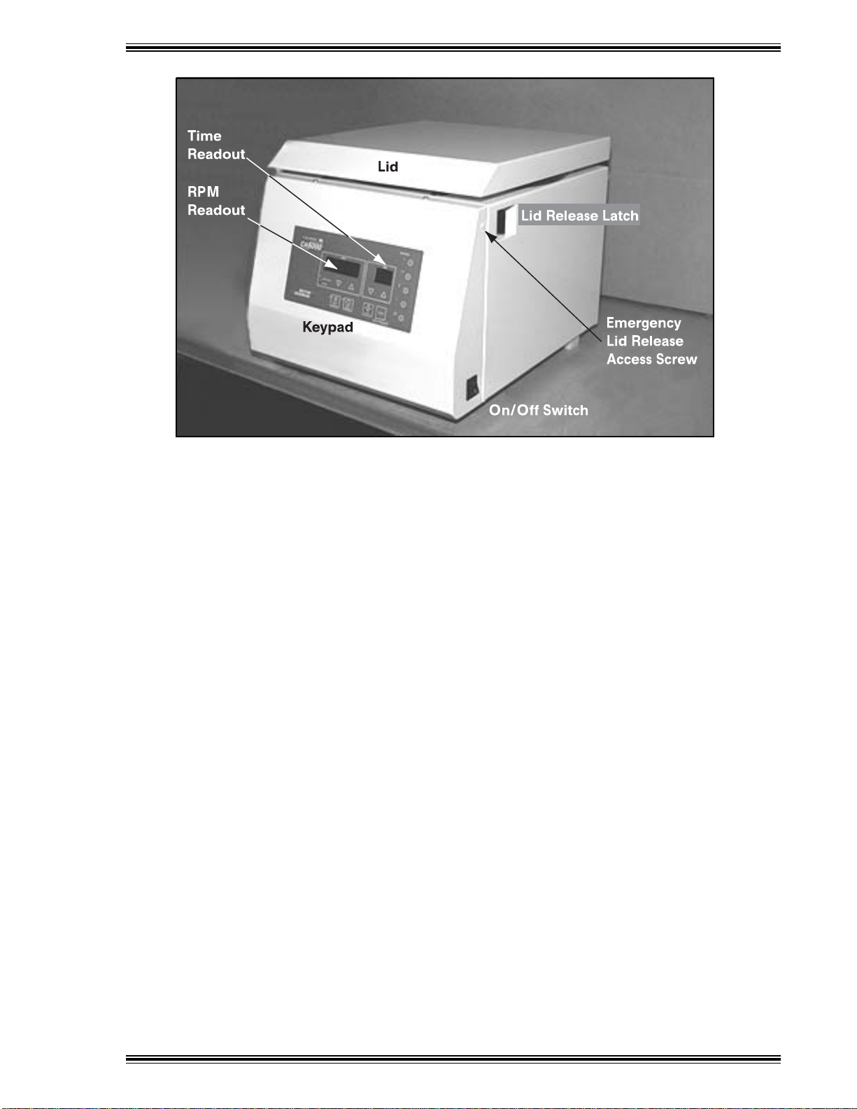
Figure 3 CA6000 Centrifuge Layout
3.3 Lid Release Latch
The Lid Release Latch is located on the right side of the centrifuge, at the top front. Pull this latch forward
to open the centrifuge lid.
Note that the Lid Release Latch does not operate when power to the unit has failed.
3.4 Emergency Lid Release ccess Screw
The emergency Lid Release Access Screw is located on the right side of the centrifuge, just in front of the
Lid Release Latch. In the event of a power failure, remove the screw to access the emergency lid release
function (see Section 4.7 .
3.5 C 6000 Keypad
The keypad is located at the center of the front panel. It presents all the keys and displays necessary to
program, start, and stop operation of the centrifuge.
3.5.1 RPM Readout
When the centrifuge is stopped, the RPM Readout displays the speed setpoint (in revolutions per minute .
It displays the actual speed when the centrifuge is spinning. When the readout is flashing, it indicates that
the current speed/time setting can be entered into memory (Program 1 5 .
3.5.2 RPM Set Keys
Press p to increase or q to decrease the speed setting. The speed can be set from 300 to 6500 rpm
in 10 rpm increments.
CA6000 Centrifuge Users Manual
MA0128 14
3.5.3 NOT IN USE Indicator
When lit, this amber LED indicates that the rotor is not spinning and the lid can be opened.
3.5.4 IN USE Indicator
When lit, this amber LED indicates that the rotor is spinning and the lid cannot be opened.
3.5.5 Time (MIN) Readout
When the centrifuge is stopped, the time readout displays the time setpoint (in minutes . It displays the
remaining time when the centrifuge is spinning. When the readout is flashing, it indicates that the current
speed/time setting can be entered into memory (Program 1 5 .
3.5.6 Time Set keys
Press p to increase or q to decrease the time setting. The time can be set from 1 minute to 99 minutes.
The Hold (Hd setting, located at the zero position, allows you to manually start and stop the centrifuge
without presetting a time (i.e., spin for an indeterminate or infinite time .
3.5.7 SOFT ACCEL Key
This key is used to select soft acceleration modes. Press and hold the key until the RPM Readout shows
ACL flashing and a number from 1 5. Use p to increase or q to decrease the acceleration profile
number. Profile 1 is the slowest setting, increasing to Profile 5, the fastest setting.
3.5.8 SOFT ACCEL Indicator
This green indicator flashes when the centrifuge is accelerating to its setpoint. The LED remains on while
the actual speed is at the setpoint.
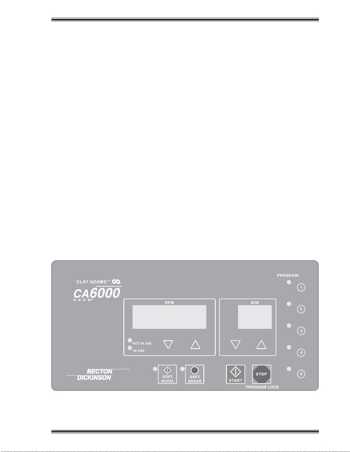
Figure 4 CA6000 Centrifuge Keypad

CA6000 Centrifuge Users Manual
MA0128 15
3.5.9 SOFT BRAKE Key
This key is used to select soft deceleration modes. Press and hold the key until the RPM Readout shows
dCL flashing and a number from 0 4. Use p to increase or q to decrease the deceleration profile
number. Profile 0 represents a coast mode (no braking .
3.5.10 SOFT BRAKE Indicator
This green indicator flashes when the centrifuge is decelerating from its setpoint. The LED remains on while
the actual speed is at the setpoint.
3.5.11 START key
Press to start a centrifuge cycle.
3.5.11 STOP/PROGRAM LOCK Key
Press this key to stop the centrifuge during its spin cycle.
Press this key ALONG WITH a PROGRAM Key to lock the program setting. When a program is locked,
it cannot be changed unless it is unlocked.
3.5.12 PROGRAM Keys
When the RPM and Time (MIN readouts are flashing, pressing one of the five PROGRAM keys saves the
current speed/time settings in memory. When RPM and Time readouts are not flashing, pressing
PROGRAM 1 5 recalls the speed/time settings stored in that memory location.
You can lock any of the programs while you are setting it by pressing the STOP/PROGRAM LOCK Key
along with the desired PROGRAM Key. When locked, a program cannot be changed. To unlock a program,
press the STOP Key along with the appropriate PROGRAM Key.
3.5.13 PROGRAM Indicators
When a preset program (1 5 is selected, the amber LED next to the PROGRAM number lights.
Table of contents
Other Becton Dickinson Laboratory Equipment manuals


