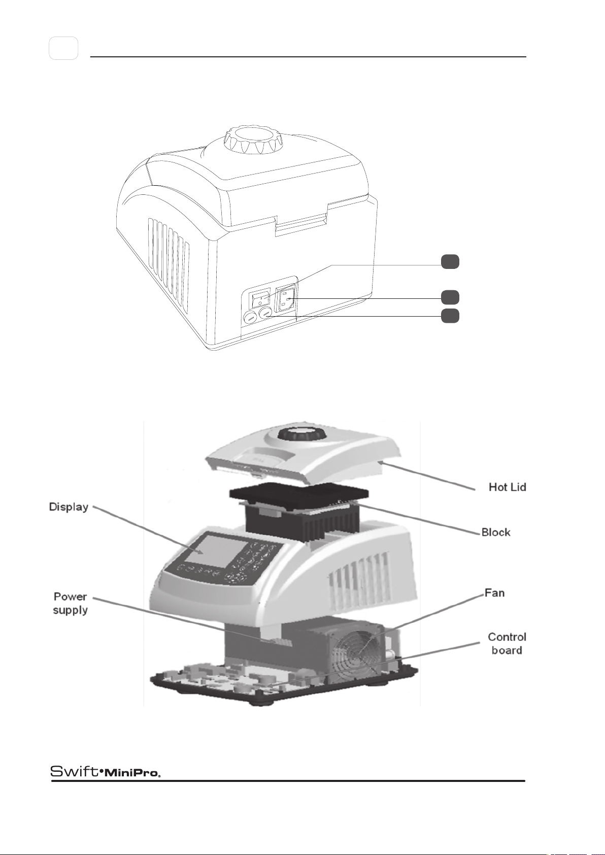
Esco Swift MiniPro SWT-MIP-0.5 Series User manual

PCR Thermal Cyclers • Real-time PCR System • Microplate Shakers / Incubators
Esco Life Science Laboratory
Equipment Solutions
Service Manual
Thermal Cyclers


Service
Manual
Thank you for purchasing the Esco Swift MiniPro
Thermal Cycler. Please read this manual thoroughly to
familiarize yourself with the many unique features and
exciting innovations we have built into cycler. You can
view this manual online at www.pcrthermalcyclers.com,
where you can find many other resources to help you
enjoy many years of productive and safe use of your
Esco equipment.
US $ 50.00
Europe € 40.00
Additional manuals can
be purchased through
your Esco Distributor
Esco SWT-MIP Service Manual (Version 1.0)
Released August 2009
For Technical Service, contact
Esco Healthcare Pte. Ltd.
21 Changi South Street 1 • Singapore 486 777
Tel +65 6542 0833 • Fax +65 6542 6920
www.pcrthermalcyclers.com • [email protected]
Thermal Cyclers

Thermal Cyclers • Service Manual

i
:
Table of Contents
Table of Contents ............................................................................................................................. i
1. Introduction .............................................................................................................................. 1
1.1 Products Covered.........................................................................................................................................1
1.2 Basic product information ..........................................................................................................................1
1.2.1 Quick View.................................................................................................................................................... 1
1.2.2 Technical specication summary table........................................................................................................... 3
1.3 Security Notes ..............................................................................................................................................4
1.4 Guidance.......................................................................................................................................................4
1.5 Maintenance tools.......................................................................................................................................4
2. Service Procedures.................................................................................................................... 7
2.1 Fan Replacement ................................................................................................................................... 7
2.2 LCD replacement..........................................................................................................................................8
2.3 Hot Lid adjust knob repair and replacement....................................................................................... 9
2.4 Hot lid repair and replacement. ...............................................................................................................10
2.5 Heating and Cooling parts Replacement ........................................................................................... 13
2.6 Printed Circuit Board Recognitions and replacement ............................................................................16
3. Troubleshooting.............................................................................................................................17
Appendix
Appendix 1: Printed Circuit Board Layout........................................................................................33
Appendix 2: Wiring Diagram ..............................................................................................................37
Appendix 3: Spare Part List.................................................................................................................39
Table of Contents

Thermal Cyclers • Service Manual

1
:
Chapter 1 • Introduction
1.1 Products Covered
This manual is applicable and specific to the following Esco products.
1.2 Basic product information
1.2.1 Quick View
Swift MiniPro Thermal Cycler (SWT-MIP)
Rated voltage (V) With 24 X 0.2ml block With 18 X 0.5ml block
100-120VAC, 50/60Hz SWT-MIP-0.2-1 SWT-MIP-0.5-1
200-240VAC, 50/60Hz SWT-MIP-0.2-2 SWT-MIP-0.5-2
CHAPTER 1
INTRODUCTION
3
1
2
4
8

2:Chapter 1 • Introduction
Thermal Cyclers • Service Manual
7
6
5

3
:
Chapter 1 • Introduction
NO NAME DESCRIPTION NOTE
1 Hot lid and Knob The Knob is for adjusting the height of the Hot Lid
Turn the knob counter-clockwise before closing
the lid. Note that the knob can be tightened by
turning it clockwise, and can be loosened by
turning counter-clockwise.
2 LCD Screen Display protocol, conditions and other information during
setting and running.
3 Keyboard For setting and controlling.
4 RS232 interface PC interface for software upgrading
5P o w e r S w i t c h Turn the equipment ON/OFF.
6P o w e r S o c k e t Connect power supply.
7 Fuse Socket Install fuse in the socket to protect equipment from over-
current.
The fuse specications are as follows: 250V
2.5A(or 125V 5A), φ5×20mm. Fuse should
be replaced by one that complies with these
specications.
8 Unlocking Device Loose the hot lid knob
If hear click sound at the beginning of turning
the knob clockwise and counter clockwise,
press the unlocking device and turn the knob
counter-clockwise for two rounds to loose the
knob
1.2.2 Technical specification summary table
General Specifications, Swift MiniPro Thermal Cycler
Model Code SWT-MIP-0.2-* SWT-MIP-0.5-*
Sample Capacity 24 x 0.2 mL 18 X 0.5 mL
Applicable Consumables 0.2 mL tubes, 3 X 8 strips, 24-well microplates 0.5 mL tubes
Max. Heating Rate 5.0°C / sec 4.0°C / sec
Max. Cooling Rate 4.0°C / sec 3.0°C / sec
Temperature Uniformity ±0.3°C
Temperature Accuracy ±0.3°C
Temperature Range 4°C - 99°C
Hot lid Temp. range 30°C - 110°C
Temp. Control Mode Block mode or tube mode
Display
Graphical LCD
Protocol Capacity
100 protocols
PC Interface
RS232 for software updates
Dimension (W x D x H)
212 × 297 × 200 mm (8.3” × 11.7” × 7.9”)
Weight
3.2 kg (7 lbs)
Electrical
100-240VAC 50/60Hz 200W
Warranty
3 years for main body, 2 years for blocks

4:Chapter 1 • Introduction
Thermal Cyclers • Service Manual
1.3 Security Notes
i. Turn the power OFF and unplug the power cord before performing any procedure.
ii. Please read all the instructions thoroughly before maintenance. Always follow this service manual. Keep this service
manual well for future reference and review it as necessary.
iii. Engineers must inspect and ensure operation of the equipment is completely back to normal after maintenance.
1.4 Guidance
Pay attention on the following before hand.
i. Investigate :-
• Situationoftheequipmentasoperating
• Previousmaintenancerecord
• Symptomofthefailure
• Hardwareenvironment
• Structureoftheequipment
• Yearsoftheequipmentbeused
ii. Check power supply.
iii. Check installation of the equipment.
iv. Clean internal of the equipment to eliminate failures caused by dust, dirt, redundant solder, welding oil.
v. Read all the instructions thoroughly before maintenance to ensure full understanding.
1.5 Maintenance tools
• Wire-strippingpliers,wirestripper
• TorquescrewdriverΦ3
• WordscrewdriverΦ2
• CrossscrewdriverΦ3
• Sharpnosepliers,diagonalcuttingnippers
• Penknife
• Tweezers
• Multimeter
• Electriciron

5
:
Chapter 1 • Introduction
Besides, a multi-channel temperature acquisition device is needed for temperature uniformity and accuracy testing.

Thermal Cyclers • Service Manual

7
:
Chapter 2 • Service Procedures
2.1 Fan Replacement
2.1.1 Remove the screws at the bottom of the unit. Refer to Fig.1. Then remove the cover.
2.1.2 The location of the fan is as Fig.2
2.1.3 Remove all connectors and take out the fan. As Fig. 3 and Fig.4
Fig.1
Fig.2
Fig.3 Fig.4
CHAPTER 2
SERVICE PROCEDURES

8:Chapter 2 • Service Procedures
Thermal Cyclers • Service Manual
2.14 Replace a new fan.
Notes: Please note the air flow direction of the fan and the polarity of the connection wire when replacing the fans. Please mark
them to avoid forgetting the correct sequence and make sure the connection is secure.
2.2 LCD replacement
2.2.1 Remove the front cover and see the LCD control board as Fig.5
2.2.2 Remove the screws as Fig.5, and get the LCD and LCD control board which are combined into one part. As Fig.6
Fig.5
Fig.6

9
:
Chapter 2 • Service Procedures
2.3 Hot Lid adjust knob repair and replacement
2.3.1Useatweezerstoremovethesmallhotlidlockdevice.AsFig.7
2.3.2 The cover will be removed together with the lock device. As Fig.8
2.3.3 Remove the small rotate metal ring. As Fig. 9
Fig.7
Fig.8
Fig.9

10 :Chapter 2 • Service Procedures
Thermal Cyclers • Service Manual
2.3.4 Remove the adjustable knob, and see the inner part .As Fig. 10
Note: Most of the time, the hot lid adjustable knob looses because the contact between the four small gears and the big gear is
broken. Please adjust and make sure the four gears are in the same level, otherwise the hot lid can not be positioned even which
will cause reagent evaporation.
2.4 Hot lid repair and replacement.
2.4.1 Remove screws as Fig.11 and Fig.12
Fig.10
Fig.11 Fig.12

11
:
Chapter 2 • Service Procedures
2.4.2 Remove the sticker, as Fig.13
2.4.3 Remove the screw, as Fig. 14
2.4.4 Remove the inner cover and see the hot lid inner part. As Fig.15
Fig.13
Fig.14
Fig.15

12 :Chapter 2 • Service Procedures
Thermal Cyclers • Service Manual
2.4.5 Remove the connector. Measure the resistance, as Fig.16. If the value is out of range, need to repair.
2.4.6 Refer to Chapter 2.3, remove the hot lid knob.
2.4.7 Remove the two screws and then remove all the white plastic gears. As Fig.17
2.4.8 The hot lid is as Fig. 18
Hot lid sensor, Resistance
should be around 10K Ω
Heating lm+ Fuse, Resis-
tance should be around 6 Ω
Fig.16
Fig.17
Fig.18
Temp. Fuse
Heating lm
Hotlid temperature Sensor

13
:
Chapter 2 • Service Procedures
2.4.9 Remove the 6 screws in above picture, the heat film is as Fig. 19
2.4.10 Remove the solder and replace heat film, fuse or sensor.
2.4.11 Solder the new fuse or sensor, and make sure the fuse contact the hot lid surface well after fixed.
2.5 Heating and Cooling parts Replacement
2.5.1 Pull the handle and put it to the center. Take out the block as Fig.20
2.5.2 Press and remove the connector as Fig. 21
Fig.19
Fig.20
Fig.21

14 :Chapter 2 • Service Procedures
Thermal Cyclers • Service Manual
2.5.3 Take out the block as Fig. 22.
2.5.4 Test the resistance as Fig.23. The resistance of TE should be around 3 Ω, and the resistance of Sensor should be
around 10KΩ. If not, need to repair the block.
2.5.5 Remove the screws as Fig.24 to remove the heat sink.
Fig.22
Fig.23
Fig.24
TE+
TE-
SEN-SINK
SEN-SINK
SEN-BLOCK
SEN-BLOCK
AUX-HEATER
AUX-HEATER
This manual suits for next models
5
Table of contents
Other Esco Laboratory Equipment manuals

Esco
Esco Cytoculture LS2-4A1 User manual

Esco
Esco MAW-4D User manual

Esco
Esco Labculture PLUS LP2-4S1 User manual

Esco
Esco Multi-zone ART Workstation User manual

Esco
Esco Labculture PLUS LP2-4S Series User manual

Esco
Esco Class II Troubleshooting guide

Esco
Esco AERIS-BG096 User manual

Esco
Esco Labculture Troubleshooting guide

Esco
Esco ETS-Lindgren GTEM! 5411 User manual

Esco
Esco Provocell User manual