BEDU SK Series Operating instructions
made for your process
Operating and
maintenance manual
Gear pump
S, SK series

www.bedu.nl

CONTENTS
1. GENERAL INFORMATION.........................................................................................................
1.1 SUPPLY CONDITIONS...................................................................................................
1.2 MANUFACTURER..........................................................................................................
1.3 USER MANUAL CONTENT............................................................................................
1.4 NAME, TYPE..................................................................................................................
1.5 NOISE EMISSIONS........................................................................................................
1.6 APPLICATION FIELDS AND LIMITS. ALLOWED AND NOT ALLOWED USES..............
2. TRANSPORT, HANDLING, PACKAGING, STORAGE...............................................................
3. DESCRIPTION OF THE PUMP AND THE PUMP UNIT..............................................................
3.1 GENERAL DESCRIPTION OF THE MACHINE...............................................................
3.2 WARNINGS....................................................................................................................
3.3 PROTECTION DEVICE ..................................................................................................
3.4 ADDITIONAL DESCRIPTION OF ACCESSORIES.........................................................
3.4.1 Seal parts............................................................................................................
4. INSTALLATION, ASSEMBLY.....................................................................................................
4.1 SPECIAL ASSEMBLY TOOLS........................................................................................
4.2 INSTALLATION SITE INFORMATION............................................................................
4.2.1 Space requirements for operation and installation...............................................
4.2.2 Inspection before starting installation ..................................................................
4.2.3 Baseplate, foundation plate details......................................................................
4.2.4 Alignment requirements ......................................................................................
4.2.5 Suction lift...........................................................................................................
4.3 INITIAL INSTALLATION..................................................................................................
4.3.1 Complete pump unit............................................................................................
4.3.2 Free shaft pump..................................................................................................
4.4 DRIVE UNIT AND ACCESSORY ASSEMBLY................................................................
4.4.1 Motor ..................................................................................................................
4.4.2 Installation of safety and control devices.............................................................
4.5 ELECTRICAL CONNECTIONS, CONNECTION CABLES ..............................................
4.6 PIPING............................................................................................................................
4.6.1 General...............................................................................................................
4.6.2 Forces and moments which operate on suction and delivery flanges. .................
4.6.3 Fastening screw torques.....................................................................................
5. COMMISSIONING, OPERATION, SHUTDOWN.........................................................................
5.1 DOCUMENTATION ........................................................................................................
5.2 PUMP PREPARATION FOR STARTUP .........................................................................
5.2.1 Filling / discharge................................................................................................
5.2.2 Electrical connections .........................................................................................
www.bedu.nl

5.2.3 Verifying the direction of rotation.........................................................................
5.3 SAFETY DEVICES .........................................................................................................
5.3.1 Mechanical safety devices (guards for rotating parts)..........................................
5.3.2 Acoustic insulation ..............................................................................................
5.3.3 Splash-proof cover..............................................................................................
5.3.4 Regulation on the electric components................................................................
5.4 STARTING THE PUMP...................................................................................................
5.4.1 Initial commissioning...........................................................................................
5.4.2 Startup after shutdowns ......................................................................................
5.4.3 Pump system requirements.................................................................................
5.4.4 Startup/shutdown frequency................................................................................
5.4.5 Operation and startup with closed valve..............................................................
5.5 SHUTDOWN...................................................................................................................
5.5.1 Decommissioning................................................................................................
5.5.2 Emptying.............................................................................................................
6. MAINTENANCE AND INSPECTION...........................................................................................
6.1 USE PRECAUTIONS......................................................................................................
6.2 WEARABLE MATERIALS...............................................................................................
6.3 SURVEILLANCE DURING OPERATION........................................................................
6.4 PREVENTIVE MAINTENANCE.......................................................................................
6.5 PUMP DISASSEMBLY AND REASSEMBLY ..................................................................
6.5.1 Tools...................................................................................................................
6.5.2 Disassembly/reassembly procedure....................................................................
7. FAULTS: CAUSES AND SOLUTIONS .......................................................................................
8. WARRANTY CONDITIONS ........................................................................................................
9. ANNEXES...................................................................................................................................
www.bedu.nl
1. GENERAL INFORMATION
1.1 SUPPLY CONDITIONS
According to Customer’s requirements, the pump can be provided both as bare shaft pump
and as pump unit. By pump unit it is meant the pump aligned with the engine, including driv-
ing elements, baseplate and any auxiliary machinery. The pumping group is supplied with
safety coupling guard.
1.2 MANUFACTURER
The pump Manufacturer is Bedu Pompen B.V.. You can apply for assistance by send-
ing a request to the following address:
Bedu Pompen B.V.
P v M Gelderland Rood 10
6666 LT HETEREN, The Netherlands
Tel: +31 (0)88 4802 900 Fax: +31 (0)88 4802 901
1.3 USER MANUAL CONTENT
This user manual provides all the necessary information to ensure a safe and correct use of
the machine. It was written –when applicable –according to point 5.5 of Standard EN 292
part 2-1992 - Machinery Safety; according to point 7 of Standard UNI EN 809-2000 Pumps
and Pump Units for Liquids - Common Safety Requirements - and according to point 1.7.4 of
Directive 98/37/EC 1998 (ex 89/392 EC). In this manual it is constantly referred to safety in-
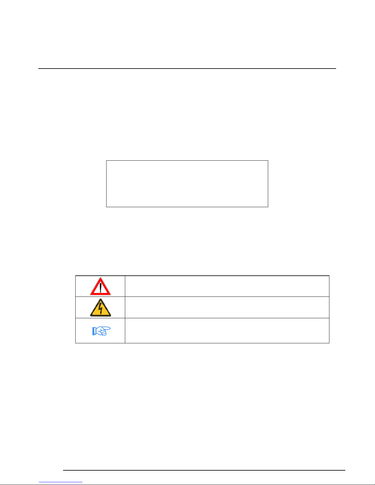
structions. Such instructions are identified by the following symbols:
It represents the safety instructions contained in this manual,
whose non-observance may compromise safety.
It is shown when electrical safety is essential to worker protection.
It indicates the safety instructions which should be taken into ac-
count for the safe operation of either the pump, the pump unit or the
pump or pump unit protection.
www.bedu.nl

1.4 NAME, TYPE
The standard pump construction is made of AISI 316L stainless steel with graphite supports
and mechanical seal in ceramic/graphite/viton. The complete series includes several models
which vary in size, materials and mechanical seals. Furthermore, the Manufacturer can also
provide models with preheating chambers, double mechanical seals, magnetic drive, sani-
tary fittings, etc. The pump identification is obtained by an alphanumeric code, an example
of which is shown below:
- 0NAX010/D0HF0C0: N type pump, A class, construction in AISI 316L stainless steel, rat-
ed flow 10 l/min. at 1500 rpm (cubic capacity 7.8 cm3/revolution), gears in AISI 316L,
graphite bushes, dual mechanical seal, equipped with preheating chamber.
1.5 NOISE EMISSIONS
-Reference standard: CEN/TC 197/SC3 N 21 E -fig.8- ISO 3744 on 6 positions
-Measured values:
1 - Equivalent weighted continuous acoustic pressure level
Leq = 75 dB(A);
2 - Maximum weighted instantaneous acoustic pressure
C (peak level) Lpc < 78 dB(C).
-Test conditions: When measuring noise, the pumped liquid (ref. to a liquid with 1 cP vis-
cosity) must be introduced into the testing system at a speed of less than 0.8 m/s into
pipes. It must however reach laminar flow regime (thus the speed must be related to the
viscosity) and the conditions outlined in this manual must be respected.
1.6 APPLICATION FIELDS AND LIMITS. ALLOWED AND NOT ALLOWED
USES
Each machine shall be used according to the type of application, operating conditions and
liquid characteristics provided in contract specifications. Each variation which alters the in-
tended use of the pump is forbidden and the User is fully responsible for it (e.g. the use of a
liquid which is corrosive to pump materials rather than the recommended fluid, etc.). For var-
iations in use within the application limits (e.g. fluid viscosity variations) it is advised to con-
tact the Manufacturer in advance.
Max. working pressure, for pumps in standard execution, is 15 bar.
In any case, the use of “KK” or alike plastic gears to allow the pump to operate also
with poorly lubricating fluids, requires greater attention to avoid excessive or unex-
pected pressure loads.
It is absolutely forbidden to use the machine in hazardous environments (explosive
atmosphere, etc…), the use of hazardous substances (e.g. fluids with dangerous gas-
es), in critical conditions (e.g. abnormal temperatures, etc…), which are not supplied
with the pump.
For pumps and pump units intended to be used in potentially explosive environ-
ments, please read carefully “Additional instructions for the operation and manage-
ment of pumps and pump units intended to be used in potentially explosive atmos-
pheres (Directive 94/9/EC)”. In case of slipping of the magnetic coupling, the surface
temperature can rise up to 350°C in few seconds; therefore the temperature close to
the coupling must be continuously checked.
Bedu Pompen B.V. declines every responsibility for the consequences arising from an im-
proper use of the machine which does not comply with what prescribed in this manual or
specifically requested when ordering.
www.bedu.nl
2. TRANSPORT, HANDLING, PACKAGING, STORAGE
Bedu Pompen sells “ex works”. Consequently, transport from the manufacturing shop to the
named place of destination is carried out by the Customer under his own responsibility. For
each transport a suitable standard packaging is ensured or established based on Customer
requirements who, in any case, must give information about the type of shipment to be per-
formed (by land, air, “overseas“).
In case of long stationary periods under critical environmental conditions (such as: high hu-
midity and/or salinity, etc.) the supply shall be stored in a protected environment.
3. DESCRIPTIONOFTHEPUMP ANDTHEPUMPUNIT
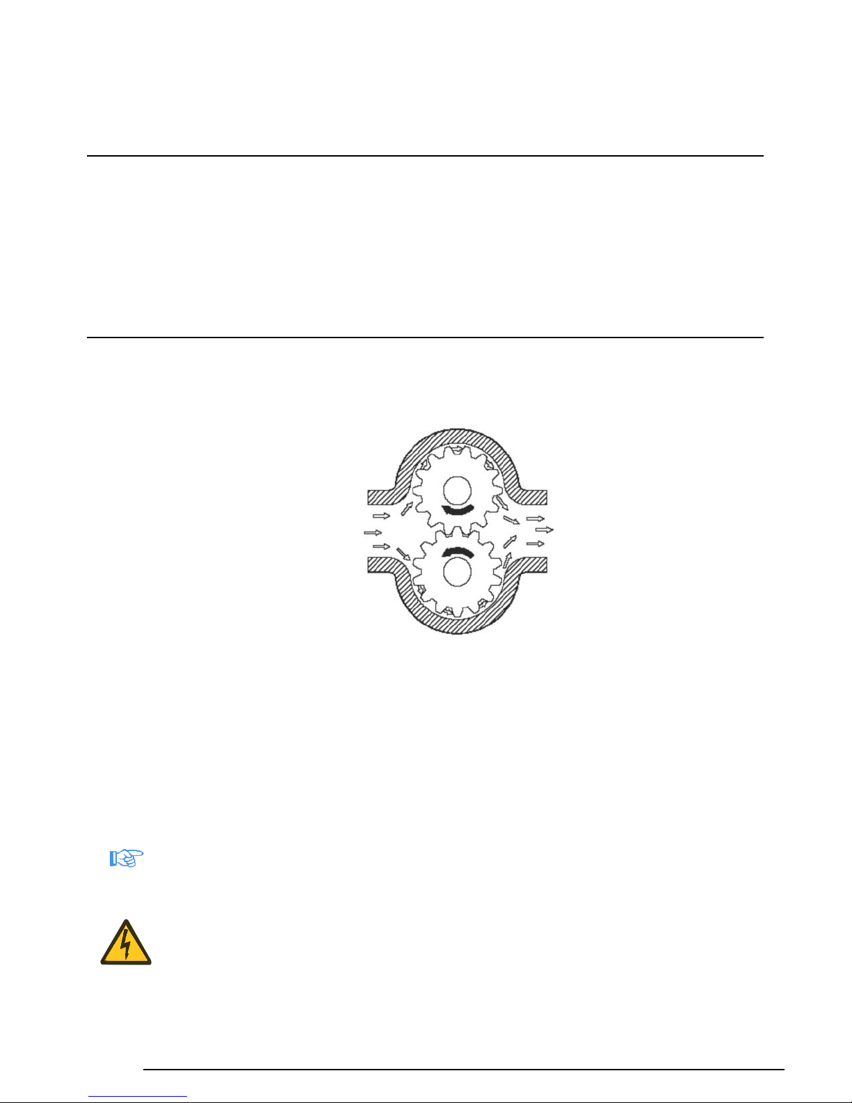
3.1 GENERAL DESCRIPTION OF THE MACHINE
Essentially the pump consists of two driven pinions which mesh one another inside a billet
machined main body, thus creating a flow of liquid between the inlet and the outlet.
The fluid containment inside the pump is ensured by a suitable seal part as defined in the
order.
The pump is attached to the electric motor, EC approved, by flexible or magnetic coupling.
The access to the coupling and the projecting segments of motor-side and pump-side shafts
is prevented by a safety coupling guard.
The pump unit can be equipped with a mechanical speed reducer or an hydraulic speed
variator for the adjustment of the rotation speed, EC approved. The assembly rests on a
strong metal baseplate.
3.2 WARNINGS
Standard construction pumps, as an indication, require a NPSH of approx. 0.4 bar. Always
calculate the maximum available suction lift, in relation to fluid characteristics, suction circuit
and operating conditions. Ensure that gears do not operate when dry. Before starting the
pump for the first time or after long stationary periods, it is advisable to fill the gear spaces
with oil or liquid being pumped through one of the nozzles and rotate the driving shaft by op-
erating manually with a screwdriver on the motor cooling fan. This also makes it possible to
check for even and smooth movement of rotary components and excessive friction. It is rec-
ommended that an overland cut-out set at approx. 10% above the motor current be installed
in the control circuit.
In our pumps the direction of rotation is clearly shown by an arrow marking the right direc-
tion.
SUCTION
DELIVERY
www.bedu.nl

The pump operating temperature in normal working conditions is about 80°C. In special
pump versions, working temperatures of 180°C and more may be achieved. To protect per-
sonnel from dangers due to the temperatures reached during the operation of the machine,
in the event of accidental contact (burn), the User must reduce the external pump tempera-
ture by means of insulation plates, coatings, screens, barriers, etc. As limit reference tem-
perature for the contact surface it is advisable to take 55°C. Below this value, for hot smooth
surfaces in bare metal, there is no burn threshold. For a detailed knowledge of this problem
in relation to different particular cases, the User can read the standard UNI EN 563 Ed.’94,
where burn thresholds are specified for several types of surface according to the “surface
temperature - contact time” parameters.
Liquids to be pumped must not contain abrasive or solid suspension as this will greatly re-
duce the pump life. At this purpose we recommend the installation of a properly sized filter
on the suction line if solids may be present.
When pumps are installed in parallel, the suction lines should be adequately separated to
prevent unnecessary turbulence.
3.3 PROTECTION DEVICE
The coupling guard installed by the Manufacturer is made of a strong metal plate, fastened
to the baseplate by screws, duly shaped to prevent fingers from coming into contact with
moving parts. It can be removed only by using a proper tool.
3.4 ADDITIONAL DESCRIPTION OF ACCESSORIES
3.4.1 Seal parts
The pump is usually supplied equipped with mechanical seal. If the Customer requires a
particular type of seal, Bedu Pompen installs the desired seal after verifying if its di-
mensions are compatible with those of the pump. In case the Customer requires only the
seal mark, the Company leaves the Manufacturer to select the type of seal, by giving infor-
mation about the pumped liquid.
Among the seals used we can mention the following:
-Single mechanical seal
- Double tandem mechanical seals with tank and pressureless flowing liquid
- Double opposed mechanical seals with external pressurized flowing liquid
These last must be installed when the pumped product has characteristics which prevent it
from being used as flowing source or for greater safety (visual inspection).
The tank for tandem mechanical seals is not pressurized and it is used to avoid dry opera-
tion of the external seal and visually detect any possible leakage of the internal mechanical
seal.
For magnetic drive pumps sealing is only ensured by static gaskets, since the pump shaft is
completely enclosed within the pump body.
www.bedu.nl

4. INSTALLATION, ASSEMBLY
4.1 SPECIAL ASSEMBLY TOOLS
To assemble the pump you do not need special tools, except for seal extractors (see
Maintenance).
4.2 INSTALLATION SITE INFORMATION
4.2.1 Space requirements for operation and installation
The space destined by the Customer to the installation of the machine should be enough to
gain access to, install and maintain the pump unit.
4.2.2 Inspection before starting installation
Before installation, the Customer must ensure that the environmental conditions of the se-
lected site comply with requirements specified under the contract.
In particular, unless expressly required and accepted in the order, the installation site should
not be exposed to the following environmental conditions:
-abnormal temperature;
-high humidity;
-corrosive atmosphere;
-explosion and/or fire hazard areas;
-dust, sandstorms;
-earthquakes and other similar external conditions;
-high level of vibrations;
-high altitude;
-flood hazard areas.
4.2.3 Baseplate, foundation plate details
The metal base plate shall be of sufficient size and strength to support induced stress.
When the pump unit is installed, it shall be firmly fixed in place by fastening bolts or by using
other securing methods.
Ground fastening bolts or other securing methods shall be of sufficient strength to prevent
the pump unit from moving accidentally.
4.2.4 Alignment requirements
The alignment operation must not submit the pump unit to axial and radial stress, therefore
the offset must always be lower than the tolerance limits expected fot the coupling.
Great care shall be taken to align pump units equipped with magnetic drive coupling.
4.2.5 Suction lift
The suction lift, that is the vertical distance between the pump inlet mid-point and the free
surface of the tank to which the pump is attached, must not exceed 5 m to allow pump prim-
ing and avoid cavitation phenomena.
www.bedu.nl

Otherwise, contact our Technical Department.
Each pump must have its own suction pipe; the installation of two or more pumps with a
common suction pipe length causes the pump to work less efficiently.
The length of the suction pipe must be reduced as much as possible to minimize pressure
losses in such segment; higher pressure losses in the discharge line do not adversely affect
the correct operation of the pump (if they do not exceed the delivery limits stamped on rating
plate).
Furthermore, it is necessary to check that siphons are not created in the suction pipe, since
the formation of air pockets generates vibrations and stresses which are not compatible with
the correct operation of the pump and may obstruct the pump priming at startup.
In case of installation below head, the pump does not ensure to be able to intercept the flow
of fluid as a shut-off cock or a proper stop valve.
NO
YES
NO
YES
www.bedu.nl
4.3 INITIAL INSTALLATION
According to the conditions of supply, the pump can be delivered as follows:
4.3.1 Complete pump unit
InthiscasetheCustomermustfastenthebaseplatetoasolidsupportinorderto ensurethecorrect axis
alignmentinalloperatingconditions.
We recommend the use of vibration dampers below the pump base and vibration damping
sections on pipes near pump inlets.
Once the pump unit has been positioned, proceed as described below:
a) connect suction and discharge pipes respectively to the pump inlet and outlet;
b) power the motor, by carefully controlling the compatibility of motor voltage and frequen-
cy with those of the system;
c) open the intake and discharge pipe valves, if any;
d) run the motor for a while to verify that the pump rotates in the direction indicated by the
arrow stamped on the pump.
4.3.2 Bare shaft pump
In this case, before following the steps described at Paragraph 4.3.1, choose the type of mo-
tor and align it to the pump on a baseplate.
The motor must be selected by the Customer depending on the type of operation for which it
is specifically requested (continuous operation, discontinuous operation, repeated startups,
indoor or outdoor installation, explosive atmosphere, critical environmental conditions, alti-
tude, etc.) with power compatible with that required by the pump.
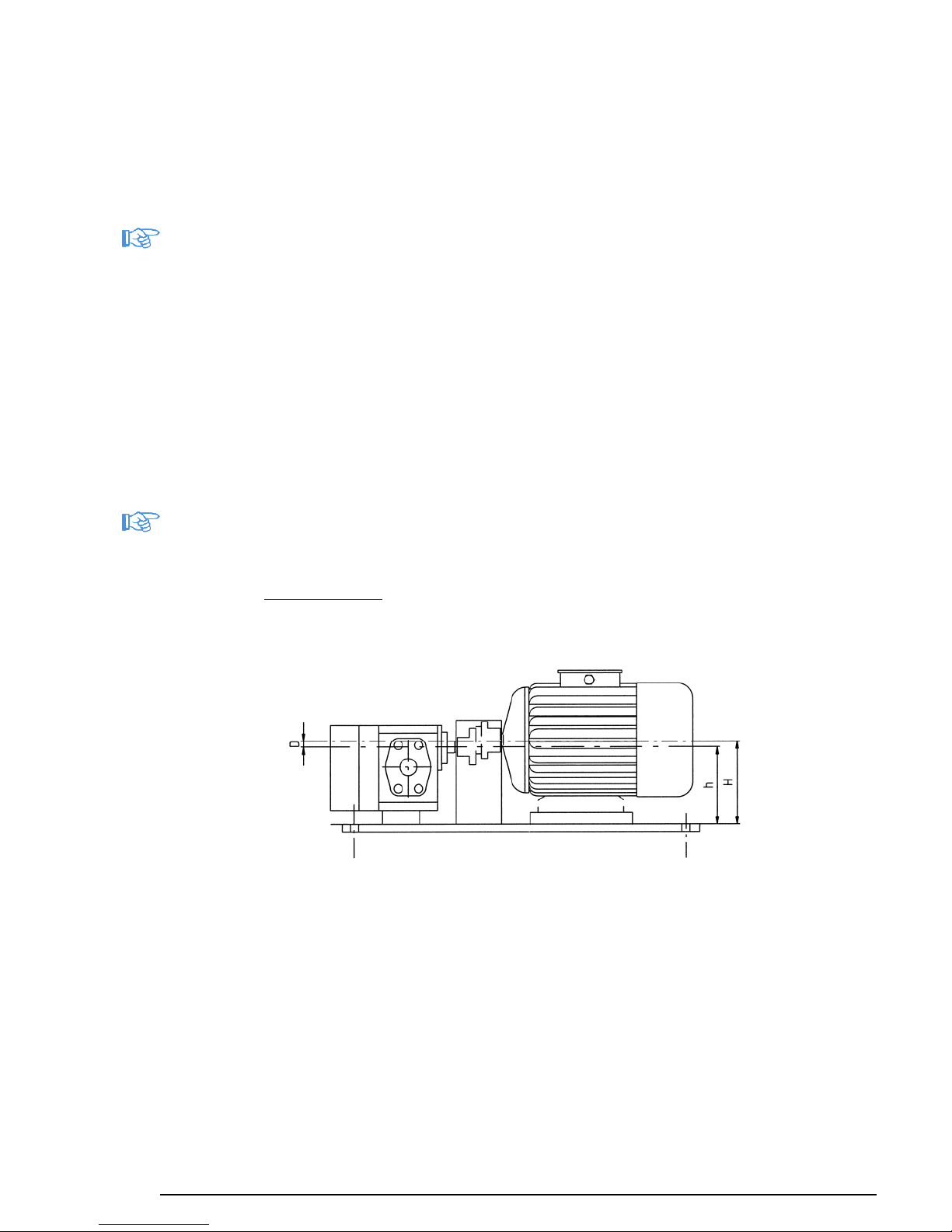
The alignment is performed by flexible or magnetic coupling on a baseplate.
To align the flexible coupling make the following basic operations:
a) accurately measure the height of the pump axis (h) and the height of the motor axis (H);
b) calculate the difference D = h –H;
c) prepare some aluminium (or steel) shims with height D;
d) place motor and pump on a single plane (verify their flatness), by placing shims where
necessary (or under the motor feet or the pump feet);
e) verify that the axes of the two shafts coincide, by measuring the two diameters by differ-
ence, that is, by accurately measuring R, D1 = 2R + d. If this equality is not verified,
properly place calibrated shims so as to align perfectly the pump unit;
www.bedu.nl

f) check that the pump axis and the motor axis are perfectly coaxial, since an offset would
cause a radial force whose strength may reduce the life of the pump or motor.
g) leave an axial clearance of approximately 2 - 3 mm between the 2 couplings, so as to
avoid stresses induced by axial forces and thermal expansions.
In case of connection by magnetic coupling, proceed as follows:
a), b), c), d) proceed as in the case of the flexible coupling;
e) verify the coaxiality between the inner magnet cover and the outer magnet cover, by ac-
curately measuring R, difference between the outer cover diameter d and the external
outer magnet diameter D1. This measurement should be made on at least 4 points at
90°; if different values are found in various measurement points, properly place calibrat-
ed shims so as to perfectly align the pump unit;
f) the non-perfect coaxiality causes differences in the air gap which induce variations of
the magnetic pull force on the inner magnet with consequent radial forces on the shaft
and wear of bushes;
g) it is also essential to avoid generating axial stress on the inner magnet, which would
cause the consequent premature deterioration of bushes, by leaving the outer magnet
free to position itself axially. After positioning the pump and the motor, it is therefore
necessary to unscrew the coupling fastening grub screw on the motor shaft and retight-
en it after the magnet has moved to its balance position.
Verify that the end of the motor shaft is at a distance of at least 2 - 3 mm (axially) from
the inner magnet cover.
It is advisable to mark by two dowel pins the position of the pump on the baseplate, so
as to make the assembly easier after maintenance operations.
When centering the outer magnet, pay particular attention to the effects of the mag-
netic pull force; in particular pay attention to your fingers (always use safety gloves)
and not to damage magnets with accidental shocks.
We recommend to use tools in non-magnetic material.
The User shall place a rigid coupling guard on the flexible or magnetic coupling: it shall be
machined so as to prevent access to moving parts.
Such coupling guard shall be firmly secured to the baseplate.
YES
NO
www.bedu.nl

4.4 DRIVE UNIT AND ACCESSORY ASSEMBLY
4.4.1 Motor
The Company installs EC approved electric motors, of power compatible with that required
by the pump, selected according to the desired operating conditions and environmental
characteristics. In particular if the pump unit is required to operate in explosive atmosphere,
the motor is chosen in explosion-proof execution (we remind that, to be used within the
European Union, also the execution of the pump and the relevant fittings must com-
ply with directive 94/9/EC).
4.4.2 Installation of safety and control devices
If specifically requested in the order form, the Company provides the pump with the relief
valve, which must be calibrated to protect the pump from damage. Once it has been proper-
ly calibrated, the valve must not be tampered with in any way, since volumetric pumps can
reach quickly, with the delivery closed, extremely high pressure values, with consequent
very serious danger.
Any pressure adjustment shall be compulsorily made with the pump stopped and de-
pressurized.
The User shall install a pressure gauge in the pump outlet, upstream of the relief valve; it is
advisable to install a vacuum gauge near the pump inlet.
In case also a safety valve is installed on the system, make sure that its calibration pressure
differs considerably from the one of the relief valve not to generate dangerous resonance
phenomena (pipe and/or valve break).
4.5 ELECTRICAL CONNECTIONS, CONNECTION CABLES
The machine shall be connected to the external ground protection system by the appropriate
terminal, which must be identified by the PE letter. Connection cables shall be properly sized
and insulated. Before energizing the machine, always verify that the mains voltage and fre-
quency are compatible with those of the motor.
4.6 PIPING
4.6.1 General
Pipes shall have a suitable diameter to allow a regular flow with low pressure losses. There-
fore, we recommend to use, at least for the suction line, pipes with inner diameter equal to
or greater than that of the pump inlet, mostly when the viscosity level becomes considerable.
To minimize pressure losses in the circuit, we recommend to avoid, as much as possible,
abrupt variations of section and direction (curves) along the pipe run, particularly in the suc-
tion line.
4.6.2 Forces and moments which operate on suction and delivery flanges.
As general rule it would be necessary to interpose flexible vibration damping sections be-
tween the pump and the system piping; therefore, we recommend to verify that the flanges
of the connection pipes are always placed, in free position, with the planes parallel to those
of the flanges of the suction and delivery nozzles to avoid that, after fastening them, forces
and moments of excessive value are generated.
In any case, the User shall make sure that the loads induced on the pump flanges, under the
most critical operating conditions, do not exceed the values prescribed by Standards UNI
EN ISO 14847.
www.bedu.nl
4.6.3 Fastening screw torques
The fastening torque for the screws of our pumps shall be:
-for M6 screws 11-12 Nm
-for M8 screws 20-22 Nm
-for M10 screws 38-40 Nm
For more detailed information, contact our Technical Department.
5. COMMISSIONING, OPERATION, SHUTDOWN
5.1 DOCUMENTATION
Operating and maintenance manual
5.2 PUMP PREPARATION FOR STARTUP
5.2.1 Filling / discharge
To prevent gears from running dry, before starting the pump for the first time or after long
stationary periods it is advisable to fill the gear spaces with oil or liquid being pumped
through one of the nozzles and rotate the driving shaft by operating manually with a screw-
driver on the motor cooling fan. This also makes it possible to check for even and smooth
movement of rotary components and excessive friction.
The pump discharge, if it is about toxic, harmful or, in any case, dangerous fluid, shall be
carried out with the greatest care. In particular, the pump body shall be emptied with appro-
priate operating manoeuvres. Later the pump (except for the NAX2.5 model) shall be sub-
mitted to a CIP cycle washing ensured by an internal drain line which, by creating a vacuum,
after partially closing the intake valve, in the bearing area and the seal chamber, removes
completely any traces of conveyed liquid.
5.2.2 Electrical connections
It is necessary to choose wires which satisfy the operating conditions required by the Cus-
tomer (e.g. voltage, current, electric shock protection, bundle of cables) and can support ex-
ternal influences (e.g. ambient temperature, presence of water or corrosive substances, me-
chanical stresses, fire hazards). Moreover, we remind that wires must be properly sized to
ensure the voltage drop from the power supply inlet to the point of load application does not
exceed 4%.
5.2.3 Verifying the direction of rotation
Open the intake and discharge valves. To verify the direction of rotation run the motor for a
while only to check that the pump rotates in the direction marked by the arrows.
5.3 SAFETY DEVICES
5.3.1 Mechanical safety devices (guards for rotating parts)
The hazardous area, represented by the projecting sections of pump side and motor side
shafts and the coupling, shall be protected against accidental contact using a duly shaped
strong metal coupling guard which must be firmly secured to the baseplate.
www.bedu.nl
5.3.2 Acoustic insulation
Sound emission values are specified in this manual. The User should always verify if the
regulations of his own country prescribe, in relation to the frequency of exposure to emission
values, the use of individual protection devices. If it is, he must comply with the require-
ments contained in the above-mentioned regulations to protect the operator’s health and
safety.
5.3.3 Splash-proof cover
In the event the liquid being pumped is dangerous, the operator must be in any case pro-
tected against the risk of any accidental contact with jets of liquid by wearing appropriate in-
dividual protection devices.
5.3.4 Regulation on the electric components
We remind that in accordance with Standard EN 60204-1 Ed1998-04, as power disconnect-
ing switch, a plug/socket combination is allowed for a machine with rated power equal to or
lower than 16 A and a total power equal to or lower than 3 kW.
5.4 STARTING THE PUMP
5.4.1 Initial commissioning
-Ensure that the pump unit is properly earthed.
-In case the pump is equipped with preheating chamber, it is necessary to operate this last
up to reach the normal operating temperature and gradually start the liquid pumping up to
reach the operating conditions in thermal equilibrium.
-Verify that suction pipes are properly joined one another to avoid air infiltrations which
would prevent the pump from priming.
-Check that siphons are not created in the suction pipes so that pump can completely re-
move the air. In this case, if the air is not completely removed then the flow rate may de-
crease and the noise level may increase although the pump has taken in the liquid, with
consequent premature deterioration of bearing bushes and moving parts.
-Where applicable, verify that the pipes for the external flow of mechanical seals are
properly connected.
-Verify the proper operation of the relief valve; to do so it is necessary to gradually increase
pressure, by acting on the valve located on the discharge pipe, up to reach the expected
calibration value. Now, after a further rotation of the valve, the discharge pressure shall
remain lower than the calibration value. Otherwise, after stopping the machine and de-
pressurizing the pump, it is necessary to disassemble the valve cap, remove the gasket
below, loosen the nut and rotate counterclockwise the spring pre-load adjusting screw
(clockwise to increase the pre-load). Retighten the lock nut, interpose the gasket and re-
screw the protection cap. The adjusting screw is not equipped with retainer, therefore
it is necessary to pay attention, when unscrewing it, not to cause a leakage of the
fluid being pumped.
5.4.2 Startup after shutdowns
The most common case in which the pump may stop working - apart from the power supply
failure (black out) –is when the electric motor overcharge protection comes into operation.
In this case, before starting the pump examine the causes which triggered the activation of
the protection and remove them.
In magnetic drive pumps, it may happen that, once the maximum transmissible torque value
has been exceeded, the pump stops while the motor is idling. In this case, it is necessary to
stop immediately the motor, wait until the inner magnet cover (which became hot as a result
of eddy currents) is cooled and restart the motor after troubleshooting.
www.bedu.nl

5.4.3 Pump system requirements
In volumetric pumps, pressure is not related to flow rate and/or rotation speed; therefore,
avoid installing shut-off valves on the discharge pipe and, in any case, between the pump
and the stop valve a relief valve must always be installed.
5.4.4 Startup/shutdown frequency
Pumps which are expressly requested by the Customer to start frequently and repeatedly do
not show any problems for this kind of operation.
5.4.5 Operation and startup with closed valve
It is forbidden to start the pump with the discharge valve closed: such mistake would
cause an abrupt pressure rise above the limit values with consequent seizing.
5.5 SHUTDOWN
5.5.1 Decommissioning
In case of decommissioning of the pump unit, it is necessary to disconnect the power supply
to make unexpected and accidental startups impossible.
5.5.2 Emptying
A pump or a pump unit which operates with a flammable, toxic, corrosive or, in any way,
hazardous fluid, or with a liquid at a temperature higher than 55°C, shall be equipped with a
device such as a connection pipe, to be provided by the User, to collect and dispose the
liquid drained or coming from any possible leakage from the shaft seal or discharged by a
pressure relief valve.
6. MAINTENANCE AND INSPECTION
Maintenance operations and pump disassembly must be performed only by author-
ized and specifically trained people.
6.1 USE PRECAUTIONS
Before performing any maintenance operation, please observe the following safety precau-
tions:
-Never execute maintenance operations with the pump running.
-Cut the power supply to the pump unit.
-Wear gloves, glasses, shoes and protective suits adequate to the characteristics of the
liquid being pumped.
-Wait until the pump is cooled.
-Never open the pump unit and/or the relief valve when the pump is pressurized.
-Close suction and discharge pipe valves, if any.
-Disconnect the pump from suction and discharge pipes, by paying attention to put a col-
lecting basin for the pipe liquid.
-In case externally flowed mechanical seals are used, disconnect the relevant pipes.
-Cut the power supply to the motor and disconnect the earth cable.
-Unscrew anchoring screws and remove the pump unit complete with its baseplate.
-Disassemble the protection coupling guard and disconnect the pump from the motor.
www.bedu.nl

-If necessary, pay particular attention to the effects of the magnetic pull force; in par-
ticular pay attention to your fingers (always wear safety gloves) and not to damage
magnets by accidental shocks. We recommend to use tools in non-magnetic mate-
rial.
-Disconnect the pump from the baseplate.
-Place a collecting basin for the pump liquid.
-Perform the maintenance operation.
-Align carefully pump and motor and fasten the pump to the baseplate.
-Connect the pump to the motor and assemble the protection coupling guard.
-Secure the baseplate by anchoring screws.
-Connect the pump to suction and discharge pipes.
-Reconnect the power supply to the motor and the earth cable.
-Open suction and discharge pipe valves, if any.
-Reconnect the power supply to the pump unit.
6.2 WEARABLE MATERIALS
The normal wear parts, included as spares in the 2-year warranty are the following:
-bearing bushes;
-seal parts (mechanical seal, gaskets);
-gears;
-shafts.
6.3 SURVEILLANCE DURING OPERATION
The pump unit does not need the presence of an Operator during the work cycle. It is up to
the User to provide or not a periodic surveillance depending on the importance and serious-
ness of the operation. The relevant checks shall be aimed to detect abnormal noise, vibra-
tion, temperature levels and/or some dripping from the mechanical seals, variations of pres-
sure and/or flow rate, etc.
6.4 PREVENTIVE MAINTENANCE
It is always advisable, for a reliable and cost-effective operation, to adopt a policy of preven-
tive maintenance. The service time specified for wearable component parts in this manual
can be used as reference for the first period of operation. Later the user will be able to im-
prove the MTBM (Mean Time Between Maintenance) as a result of the acquired experience.
6.5 PUMP DISASSEMBLY AND REASSEMBLY
6.5.1 Tools
No special tools are requested, except for seal extractors.
6.5.2 Disassembly/reassembly procedure
Before disassembling the pump, it is necessary to perform the operations mentioned at point
6.1 "USE PRECAUTIONS".
Refer to the drawings and nomenclature attached at the end of the manual.
www.bedu.nl

1) Single seal (see Figure 1)
a) Access to the mechanical seal
After removing the feather key from its seat, loosen the hexagonal head screws of the
seal cover and extract it, by paying attention not to damage the seal static part ,
housed in the cover. It is thus possible to check the state of wear and tear of the seal con-
tact surfaces. On reassembly, pay attention not to pinch the sealing O-ring housed in the
cover.
b) Replacing static seal
To remove the static part of the seal from the seal cover , it is necessary to extract, by
using special pliers, the seeger ring housed in the cover, remove the ball bearing and
exert a pressure upon the external side of the seal. After placing the seal cover on a plane
and greasing the walls to make assembly easier, insert the new static seal with the relevant
O-ring; use a pad interposed with a soft bearing to exert the force perpendicularly to the
cover.
c) Replacing dynamic seal
To remove the dynamic part of the seal it is advisable to use an iron wire bent at 90° at
one end to hook the first or the second coil of the seal spring . Exert a traction force paral-
lel to the shaft , by paying attention not to scratch this last. After greasing the shaft to
make assembly easier, insert the new mechanical seal by rotating the spring in the direction
opposite to that of the coil; use a pad interposed with soft bearing to press the seal up to
make the spring rest on the projection (or on the seeger B) provided on the shaft.
2) Double back-to-back seals (see Figure 2)
a) Access to the external mechanical seal
After removing the feather key from its seat, loosen the hexagonal head screws of the ex-
ternal seal cover and remove this last, by paying attention not to damage the static part of the
external seal , housed in the cover. It is thus possible to check the state of wear and tear of the
external seal contact surfaces. On reassembly, pay attention not to pinch the sealing O-ring
housed in the cover.
b) Replacing static seals
To remove the static part of the external seal from the seal cover , it is necessary to ex-
tract, by using special pliers, the seeger ring housed in the cover, remove the ball bearing
and exert a pressure upon the external side of the seal. After placing the seal cover on a
plane and greasing the walls to make assembly easier, insert the new static seal with the
relevant O-ring; use a pad interposed with a soft bearing to exert the force perpendicularly
to the cover.
To gain access to the static part of the internal seal, proceed as described at points c),e).
By acting from the back of the front body insert the point of a screwdriver in the existing cavi-
ty between the tang of the static part of the internal mechanical seal and the bush which
houses this last (the bush is forced into the body and cannot be disassembled); with
small blows on the surrounding area, it is possible to remove the fixed seat of the mechani-
cal seal .
On assembly, after reassembling gears and shafts as described at point e), place the pump
on a plane, grease the bush walls to make assembly easier, insert the new static seal
with the relevant O-ring by using a pad interposed with a soft bearing to exert the force per-
pendicularly to the cover.
www.bedu.nl
c) Replacing dynamic seals
To remove the dynamic part of the external seal it is advisable to hold the spring and,
with a rotation movement in the same direction as that of its coil, exert a traction force paral-
lel to the shaft D, by paying attention not to scratch this last. After greasing the shaft to
make assembly easier, insert the new mechanical seal by rotating the spring in the direction
opposite to that of the coil; use a pad interposed with a soft bearing to press the seal up to
make the spring rest on the stop ring fixed on the shaft.
To replace the dynamic part of the internal seal , it is necessary to disassemble the ring
, fixed on the shaft by means of threaded grub screws . We recommend to mark accu-
rately the ring position on the shaft before disassembly, so as to ensure the correct
seal pre-load later. To remove the dynamic part of the internal seal it is advisable to use
an iron wire bent at 90° at one end to hook the first or the second coil of the seal spring .
Exert a traction force parallel to the shaft D, by paying attention not to scratch this last.
Make sure that grub screws did not scratch the shaft D.
After greasing the shaft to make assembly easier, insert the new mechanical seal by rotating
the spring in the direction opposite to that of the coil; use a pad interposed with a soft bear-
ing to press the seal up to make it match the fixed part . Secure the ring in the original
position and lock it on the shaft D by using grub screws .
During operation, payattention not to invert seals and relevant springs.
3) Double tandem mechanical seals (see Figure 3)
a) Access to the external mechanical seal
Place a basin of suitable size and capacity under the seal cover and, by loosening the
grub screw , empty the tank .
After removing the feather key from its seat, loosen the hexagonal head screws of the
external seal cover and extract this last, by paying attention not to damage the static part
of the external seal , housed in the cover. It is thus possible to verify the state of wear and
tear of the external seal contact surfaces. On reassembly, pay attention not to pinch the
sealing O-ring housed in the cover. Retighten the grub screw and fill the tank with
the recommended fluid.
b) Replacing static seals
To remove the static part of the external seal from the seal cover , it is necessary to ex-
tract, by using special pliers, the seeger ring housed in the cover, remove the ball bearing
and exert a pressure upon the external side of the seal. After placing the seal cover on a
plane and greasing the walls to make assembly easier, insert the new static seal with the
relevant O-ring; use a pad interposed with a soft bearing to exert the force perpendicularly
to the cover.
To gain access to the static part of the internal seal, proceed as described at point c), with-
out disassembling the dynamic part of the internal seal . By exerting a pressure on the ex-
ternal side of the seal, remove the fixed seat of the internal mechanical seal from the
flange . After placing this last on a plane and greasing the walls to make assembly easier,
insert the new static seal with the relevant O-ring; use a pad interposed with a soft bearing
to exert the force perpendicularly to the cover. On reassembly, pay attention not to pinch the
sealing O-ring housed in the flange .
www.bedu.nl
c) Replacing dynamic seals
To remove the dynamic part of the external seal it is advisable to hold the spring and,
with a rotation movement in the same direction as that of its coil, exert a traction force paral-
lel to the shaft D, by paying attention not to scratch this last. After greasing the shaft to
make assembly easier, insert the new mechanical seal by rotating the spring in the direction
opposite to that of the coil; use a pad interposed with a soft bearing to press the seal up to
make the spring rest on the external stop ring fixed on the shaft.
To replace the dynamic part of the internal seal , it is necessary to disassemble the exter-
nal ring , secured on the shaft by means of threaded grub screws . We recommend to
mark accurately the ring position on the shaft before disassembly, so as to ensure
the correct seal pre-load later. Loosen the hexagonal head screws and disassemble
the flange (with the static part of the internal mechanical seal) and the O-ring . To ex-
tract the dynamic part of the internal seal it is advisable to use an iron wire bent at 90° at
one end to hook the first or the second coil of the seal spring . Exert a traction force paral-
lel to the shaft D, by paying attention not to scratch this last. Ensure that grub screws
did not scratch the shaft D.
After greasing the shaft to make assembly easier, insert the new mechanical seal by rotating
the spring in the direction opposite to that of the coil; use a pad interposed with a soft bear-
ing to press the seal up to make the spring rest on the internal ring (or on the seeger)
fixed on the shaft.
4) Magnetic drive coupling (see Figure 4)
a) Access to inner magnet
Place a basin of suitable size and capacity under the inner magnet cover; loosen the hexag-
onal head screws and disassemble the cover and the O-ring . Unscrew the screw
, remove the washer and disassemble the inner magnet . On reassembly, pay atten-
tion not to pinch the sealing O-ring housed on the centering ring . We recommend the
use of tools in non-magnetic material.
d) Replacing bearing bushes
Proceed as described at points a), b), c), e). To replace the graphite bearing bushes , it is
necessary to break them with a chisel or other convenient tool, by paying great attention not
to damage the seat diameter of bushes and their base plane. Before inserting new bushes,
clean very carefully bush seats with alcohol in order to remove all impurities and dry well. Fit
new bushes by spreading a layer of glue of “LOCTITE 648” type over their outer diameters,
by paying attention that the cut bush and the integer bush match perfectly. First introduce
the integer bush and then the other, by letting glue dry for about 1015 minutes. When the
operation is over, set to zero the bush shims with the relevant housing covers. If a surfacing
feed is not available, you can choose a base plane abraded with fine emery cloth with P80
type grain for rough grinding and 400 type grain for finishing, by making a circular motion.
For assembly, follow the instructions at points e), c), b), a).
e) Replacing gears and shafts
Proceed as described at points a), b), c). Loosen the hexagonal head screws which fas-
ten the rear cover and remove this last, by keeping into account that the operation may
become difficult for the accuracy of shafts and dowel pins . For pumps of size greater than
that of NEX400, loosen the hexagonal head screws on the front cover.
f) Safety valve replacement
www.bedu.nl
This manual suits for next models
1
Table of contents
Other BEDU Water Pump manuals


Popular Water Pump manuals by other brands


Davey
Davey M5138 Installation and operating instructions

DAB
DAB DAB E.SYBOX Instruction for installation and maintenance

EBARA
EBARA 3D Operating and maintenance manual

Mixtron
Mixtron MXO1.075.P110.00 Operating and maintenance manual

Crane
Crane 4SHM Installation and operation manual

Graco
Graco Husky 715 instructions

SFA
SFA SANIWALL PRO UP installation instructions

Cosmo
Cosmo DN 25 Instructions for use

Xylem
Xylem GOULDS NPO instruction manual

Watson-Marlow
Watson-Marlow 323S user manual

GEA
GEA ARIETE Instructions for use and maintenance

GORMAN-RUPP PUMPS
GORMAN-RUPP PUMPS SE Series Installation, operation, and maintenance manual with parts list