Beechcraft TRAVEL AIR 95 Install guide
eecheraft
TRAVEL
AIR
95 (TD-2 thru TD-302)
B95 (TD-303 thru TD-452)
B95A (TD-453 thru TD-533)
D95A (TD-534 thru TD-707)
E95 (TD-708 thru TD-721)
SHOP MANUAL
95-590001-1 C95-590001-1 C4
Reissued: September 15, 1967 Revised: June 24, 1983

PUBLISHED BY
COMMERCIAL PRODUCT SUPPORT
BEECH AIRCRAFT CORPORATION
WICHITA, KANSAS 67201
U. S. A.
Member of GAMA
General Avianon ARaytheon Company
Manyforturers Association

Listed below are the pages required for this publication. with effectivity current through the revision and or retssue code shown
on the lower right corner of this page and on the title page. Each page is followed by an entry that denoles whether the page
sstill as onginally issued or is apart of some later revision or reissue
Always destroy superseded pages when you insert revised pages.
CReissue September 15, 1967
01 Revision November 30, 1976
C2 Revision November 4, 1977
C3 Revision August 10, 1978
C4 Revision June 24, 1983
EFFECTIVE PAGES
Title Page C4 June 24, 1983 4-7 and 4-8 C4 June 24, 1983
APage C4 June 24, 1983 4-9 and 4-10 CSeptember 15, 1967
ithru iv C3 August 10, 1978 4-10A C3 August 10, 1978
1-1 C4 June 24, 1983 4-11 C3 August 10, 1978
1-3 thru 1-6 CSeptember 15, 1967 4-12 and 4-12A C4 June 24, 1983
2-1 thru 2-8 CSeptember 15, 1967 4-13 thru 4-20 C September 15, 1967
2-9 C4 June 24, 1983 5-1 thru 5-17 C September 15, 1967
2-10 thru 2-20 CSeptember 15, 1967 5-18 thru 5-23 C3 August 10, 1978
3-1 CSeptember 15, 1967 6-1 thru 6-11 CSeptember 15, 1967
3-2 and 3-2A C*4 May, 1970 6-12 AMEND 111March, 1969
3-3 thru 3-4 CSeptember 15, 1967 6-13 thru 6-38 CSeptember 15, 1967
3-5 C2 November 4, 1977 6-39 AMEND III March, 1969
3-6 CSeptember 15, 1967 6-40 thru 6-47 CSeptember 15, 1967
3-6A and 3-6B C1 November 30, 1976 6-48 AMEND lil March, 1969
3-7 C2 November 4, 1977 6-49 thru 6-60 C September 15, 1967
3-8 CSeptember 15, 1967 7-1 thru 7-3 C3 August 10, 1978
3-9 C1 November 30, 1976 8-1 C3 August 10, 1978
3-10 thru 3-15 CSeptember 15, 1967 8-2 C3 August 10, 1978
3-16 and 3-17 C/6 October, 1971 8-3 CSeptember 15, 1967
3-18 thru 3-74 CSeptember 15, 1967 8-4 C3 August 10, 1978
4-1 CSeptember 15, 1967 8-5 C4 June 24, 1983
4-2 thru 4-6G C4 June 24, 1983
Basic publications are assigned apart number which appears on the title page with the date of the issue. Subsequent
revisions are identified by the addition of arevision code after the part number Al after apart number denotes the first
revision to the basic publication, A2 the second. etc. Occasionally, it is necessary to completely reissue and reprint a
publication for the purpose of obsoleting aprevious issue and outstanding revisions thereto. As these replacement reissues
are made, the code will also change to the next successive letter of the alphabet at each issue. For example. Bfor the first
reissue. Cfor the second reissue, etc.
When ordering a manual, give the basic number. and the reissue code when applicable. if acomplete up-to-date publication is
desired. Should only revision pages be required, give the basic number and revision code for the particular set of revision
pages you desire.
A
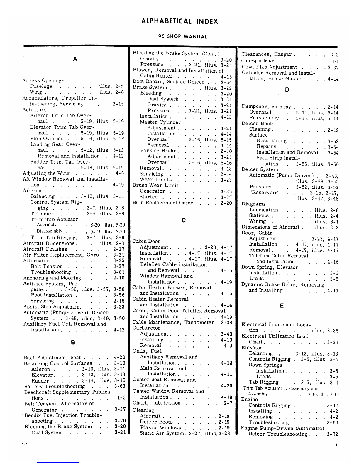
ALPHABETICAL INDEX
95 SHOP MANUAL
Bleeding the Brake System (Cont. )Clearances, Hangar .....2-2
AGravity ...... . .3-20 Correspondence I-I
Pressure . . .3-21, illus. 3-21 Cowl Flap Adjustment ....3-37
Blower, Removal and Installation of Cylinder Removal and Instal-
Cabin Heater ... . 4-15 lation, Brake Master . . .4-14
Access Openings Boot Repair, Surface Deicer ..3-54
Fuselage . . . . .illus. 2-5 Brake System . . ...illus. 3-22 O
Wing .......illus. 2-6 Bleeding .. . . . . .3-20
Accumulators, Propeller Un- Dual Systeth . . .. . 3-21
feathering, Servicing ...2-15 Gravity .. . . .. . 3-21 Dampener, Shimmy .. . . . 2-14
Actuators Pressure . . 3-21, illus. 3-21 Overhaul ..5-14, illus. 5-14
Aileron Trim Tab Over- Installation .. . .. . . 4-13 Reassembly. .5-15, illus. 5-14
haul ....5-19, illus. 5-19 Master Cylinder Deicer Boots
Elevator Trim Tab Over- Adjustment .. . . . . 3-21 Cleaning. .......2-19
haul .. . .5-19, illus. 5-19 Installation .. . . . .4-14 Surface
Flap Overhaul ..5-16, illus. 5-18 Overhaul ..5-16, illus. 5-15 Resurfacing ... . .3-52
Landing Gear Over- Removal . . . . . . 4-14 Repairs ...... . 3-54
haul ....5-12, illus. 5-13 Parking Brake. . . . . . 2-10 Installation and Removal .3-54
Removal and Installation .4-12 Adjustment . . . . . . 3-21 Stall Strip Instal-
Rudder Trim Tab Over- Overhaul . . 5-16, illus. 5-16 lation. .3-55, illus. 3-56
haul ....5-18, illus. 5-19 Removal. .. . ....4-13 Deicer System
Adjusting the Wing . . .. . 4-6 Servicing . . .. . . . 2-14 Automatic (Pump-Driven) .3-48,
Aft Window Removal and Installa- Wear Limits . . . ...3-23 illus. 3-49, 3-50
tion ........ . 4-19 Brush Wear Limit Pressure ..3-52, illus, 3-53
Alleron Generator . . . ....3-35 "Reservoir". ...2-15, 3-47,
Balancing ...3-10, illus. 3-11 Starter ...... . . 3-37 illus. 3-47, 3-48
Control System Rig- Bulb Replacement Guide . . . 2-20 Diagrams
ging .... . 3-7, illus. 3-8 Lubrication .... . illus. 2-8
Trimmer . . . . 3-9, illus. 3-8 Stations ... . ..illus. 2-4
Trim Tab Actuator CWiring ......illus. 6-1
Assembly 5-20, illus. 5-20 Dimensions of Aircraft . . illus. 2-3
Disassembly 5-19, illus. 5-20 Door, Cabin
Trim Tab Rigging. .3-7, illus. 3-8 Adjustment . . . . 3-23, 4-17
Aircraft Dimensions ...illus. 2-3 Cabin Door Estallation ..4-17, illus. 4-17
Aircraft Finishes .....2-17 Adjustment .. . ..3-23, 4-17 Removal. ..4-17, illus. 4-17
Air Filter Replacement, Gyro .3-31 Installation . . . 4-17, illus. 4-17 Teleflex Cable Removal
Alternator . . 3-35 Removal. ...4-17, illus. 4-17 and Installation ....4-15
Belt Tension .. . ...3-37 Teleflex Cable Installation Down Spring, Elevator
Troubleshooting .....3-61 and Removal ... . . 4-15 Installation .... . ..3-5
Anchoring and Mooring ... . 2-10 Window Removal and Loads . . . . . . . .3-5
Anti-ice System, Pro- bstallation ,,.. . .4-19 Dynamic Brake Relay, Removing
eller 3-56 illus. 3-57, 3-58 Cabin Heater Blower, Removal and Installing , . . . . . 4-13
''and Installation 4-15
Boot Installation .....3-56 •• • • •
2-15 Cabin Heater Removal
Servicing . . . . ..and Installation ... . . 4-14 E
Assist Step Adjustment ....3-23 Cable, Cabin Door Teleflex Removal
Automatic (Pump-Driven) Deicer and Installation . . . . . 4-15
System ..3-48, illus. 3-49, 3-50
Auxiliary Fuel Cell Removal and Cable Maintenance, Tachometer .3-38 Electrical Equipment Loca-
Installation . . . . ..,4-12 Carburetor tion .. . . . .illus. 3-36
Adjustment . . . . . . .3-40 Electrical Utilization Load
Installing . . . .....4-10 Chart. . . ... . ..3-37
Removal . . . . .. . 4-9 Elevator
Cells, Fuel Balancing ..3-12, illus. 3-13
Back Adjustment, Seat ... , 4-20 Auxiliary Removal and Controls Rigging .3-5, illus. 3-4
Balancing Control Surfaces , , 3-10 Installation . . .. . ,4-12 Down Springs
Aileron .. . .3-10, illus. 3-11 Main Removal and Installation ... . ..3-5
Elevator ....3-12, illus, 3-13 Installation ... . . . 4-11 Loads .... . ..3-5
Rudder ....3-14, illus. 3-15 Center Seat Removal and Tab Rigging ..3-5, illus. 3-4
Battery Troubleshooting ...3-63 Installation .. . .. . .4-20 Trim Tab Actuator Disassembly and
Beechcraft Supplementary Publica. Center Window Removal and Assembly . . .5-19. illus. 5-19
tions . . . . .....1-5 Installation . . . . . . . 4-19 Engine
Belt Tension, Alternator or Chart, Lubrication . . ...2-7 Controls Rigging .. . . . 3-47
Generator . . .. . 3-37 Cleaning Installing ..... . .4-2
Bendix Fuel Injection Trouble- Aircraft . . . . . . . . 2-19 Removing ...... . 4-2
shooting .....3-70 Deicer Boots . . ... . 2-19 Troubleshooting ... . 3-66
Bleeding the Brake System . . 3-20 Plastic Windows . . . . . 2-19 Engine Pump-Driven (Automatic)
Dual System ...3-21 Static Air System. 3-27, illus.3-28 Deicer Troubleshooting. . . 3-72
C3 i
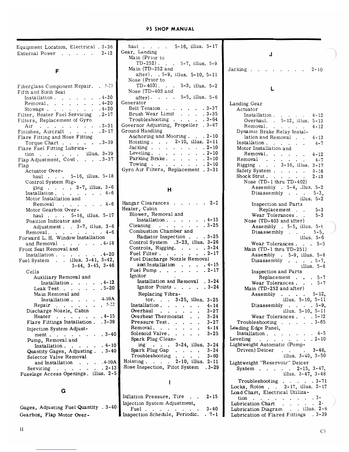
95 SHOP MANUAL
Equipment Location, Electrical .3-36 haul ... . 5-16, illus. 5-17
External Power ... . .2-12 Gear, Landing
Main (Prior to
TD-252) . . .5-7, illus. 5-9
FMain (TD-252 and Jacking ....... . 2-10
after) . . 5-9, illus. 5-10, 5-11
Nose (Prior to
Fiberglass Component Repair. .5-23 TD-403) .. . 5-3, illus. 5-2 L
Fifth and Sixth Seat Nose (TD-403 and
Installation .. . . . . .4-20 after) .. . .5-5, illus. 5-6
Removal. .. . . . ..4-20 Generator LandingGear
Stowage ..., , .. . 4-20 Belt Tension ......3-37 Actuator
Filter, Heater Fuel Servicing .2-17 Brush Wear Limit ... . 3-35 Installation ...4-12
Filters, Replacement of Gyro Troubleshooting .....3-64 Overhaul. .5-12, illus. 5-13
Air .. . ..... . 3-31 Governor Adjusting, Propeller .3-47 Removal. ..4-12
Finishes,Aircraft ... . .2-17 GroundHandling DynamicBrakeRelayInstal-
Flare Fitting and Hose Fitting Anchoring and Mooring ...2-10 lation and Removal ..4-13
Torque Chart . . . . ..3-39 Hoisting .. . 2-10, illus. 2-11 Installation . . . . . .4-7
Flare Fuel Fitting Lubrica- Jacking ........2-10 Motor Installation and
tion , , . . . . illus. 3-39 Leveling ... . 2-10 Removal. . . . . .4-12
Flap Adjustment, Cowl . . . . 3-37 Parking Brake .. . . . . 2-10 Removal .. . . . .4-7
Flap Towing .. . .. . . . 2-10 Rigging ...3-16, illus. 3-17
Actuator Over. Gyro Air Filters, Replacement .3-31 Safety System .....3-18
haul . . . 5-16, illus. 5-18 Shock Strut . . . . . . 2-13
Control System Rig- Nose (TD-1 thru TD-402)
ging . . . . 3-7, illus. 3-6 HAssembly .5-4, alus. 5-2
Installation .... . ..4-6 Disassembly . . .5-3,
Motor Installation and illus. 5-2
Removal . . ....4-6 Hangar Clearances ... . . 2-2 Inspection and Parts
Motor Gearbox Over- Heater, Cabin Replacement . . 5-3
haul .. . 5-16, illus. 5-17 Blower, Removal and Wear Tolerances ..5-3
Position Indicator and Installation ... . . . 4-15 Nose (TD-403 and after)
Adjustment ..3-7, illus. 3-6 Cleaning . . .... . 3-25 Assembly .5-5, illus. 5-E
Removal. . . . . . ..4-6 Combustion Chamber and Disassembly .. . 5-5,
Forward L. H. Window Installation Radiator Inspection .. . 3-25 illus. 5-6
and Removal . . . . ..4-18 Control System .3-23, illus. 3-26 Wear Tolerances ...5-5
Front Seat Removal and Controls, Rigging. . . . . 3-24 Main (TD-1 thru TD-251)
Installation . . .. . ..4-20 Fuel Filter . . . . . . .2-17 Assembly .5-9, illus. 5-8
Fuel System . . illus. 3-41, 3-42, Fuel Discharge Nozzle Removal Disassembly . . . . 5-7
3-44, 3-45, 3-46 anctinstallation ... . 4-15 illus. 5-8
Cells Fuel Pump . . . . . . .2-17 Inspection and Parts
Auxiliary Removal and Ignitor Replacement ...5-7
Installation .....4-12 Installation and Removal .3-24 Wear Tolerances . . .5-7
Leak Test . . .. . .5-20 Ignitor Points .....3-24 Main (TD-252 and after)
Main Removal and Replacing Vibra- Assembly .. . .5-12,
Installation ....4-10A tor. ..3-25, illus. 3-25 illus. 5-10, 5-11
Repair .. . . . . .5-22 Installation . . ... . 4-14 Disassembly . . . . 5-9,
Discharge Nozzle, Cabin Overhaul . . . . . . 3-27 illus. 5-10, 5-11
Heater . . . .. . .4-15 Overheat Thermostat ..3-24 Wear Tolerances .. . 5-12
FlareFittingsInstallation. .3-39 PressureTest. . . . . 3-27 Troubleshooting. . . ..3-65
Injection System Adjust. Removal. ... . . . 4-14 Leading Edge Panel,
ment . . .... . .3-40 Solenoid Valve .. . . . 3-25 Installation .... . . .4-5
Pump, Removal and Spark Plug Clean- Leveling .. . . . . ..2-10
Installation . . . . ..4-10 ing . . . 3-24, illus. 3-24 Lightweight Automatic (Pump-
QuantityGages, Adjusting ..3-40 Spark Plug Gap . . . . 3-24 Driven) Deicer . . . 3-48,
Selector Valve Removal Troubleshooting . . . . 3-60 illus. 3-49, 3-50
and Installation . . ..4-10A Hoisting . . . . 2-10, illus. 2-11 Lightweight "Reservoir" Deicer
Servicing .. . .. . .2-13 Hose Inspection, Pitot System .3-29 System . . . ..2-15, 3-47,
Fuselage Access Openings. illus. 2-5 illus. 3-47, 3-48
Troubleshooting ... . .3-71
Locks, Roton ..2-17, illus. 2-17
GLoad Chart, Electrical Utiliza-
Inflation Pressure, Tire . . 2-15 tion ..... . . . .3-
Injection System Adjustment, Lubrication Chart . . ...2:
Gages, Adjusting Fuel Quantity .3-40 Fuel . . ... . ..3-40 Lubrication Diagram ..illus. 2-8
Gearbox, Flap Motor Over- Inspection Schedule, Periodic. .7-1 Lubrication of Flared Fittings .3-39
C3

95 SHOP MANUAL
Oil Pressure Fluctuations . . .3-40 Rigging (cont'd.)
MOil System, Servicing .. . .2-12 Aileron . . .3-7, illus. 3-8
Openings, Access Aileron Trim
Magnetos . . . .....2-12 Fuselage. .....illus. 2-5 Tab .. . 3-7, illus. 3-8
Timing ........3-33 Wing .. . ....illus. 2-6 Elevator . . . 3-5, illus. 3-4
Troubleshooting .....3-68 Overhaul and Replacement Elevator Trim
Main Fuel Cell Removal and Schedule . . .. . . . .8-1 Tab ...3-5, illus. 3-4
Installation . . 4-11 Oxygen System, Flap . . . . 3-7, illus. 3-6
Main Landing Gear (TD-1 thru Servicing ..2-15, illus. 2-16 Rudder ...3-2, illus. 3-3
TD-251) Rudder Trim
Assembly . . .5-9, illus. 5-8 Tab .. . 3-2, illus. 3-3
Disassembly . . 5-7, illus. 5-8 PLanding Gear ..3-16, illus. 3-17
Inspection and Parts Replace- Roton Locks .. .2-17, illus. 2-17
ment 5-7 Rudder
Wear Tolerances ..5-7 Paralleling Relay Adjustment. .3-34 Balancing ...3-14, illus. 3-15
Main Landing Gear (TD-252 and Parking Brake .. . . . . . 2-10 Controls Rigging .3-2, illus. 3-3
after) Adjustment .. . . . . . 3-21 Tab Rigging ..3-2, illus. 3-3
Assembly ......5-12, Valve Overhaul .5-16, illus. 5-16 Travel Measuring. 3-2, illus. 3-2
illus. 5-10, 5-11 Periodic Inspection Schedule ..7-1 Trim Tab Actuator
Disassembly ... . . 5-9, Pitot System ..3-27, illus. 3-28 Disassembly .5-18, illus. 5-19
illus. 5-10, 5-11 Power, External .. . . ..2-12 Assembly 5-\9, illus 509
Wear Tolerances .... . 5-12 Powerplant, Removing and
Master Cylinder, Brake Installing .... . ..4-2 S
Installation . . . . 4-14 Pressure System ..3-29, illus. 3-32
Linkage Adjustment ... . 3-21 Pressure Surface Deice Safety System, Landing Gear ..3-18
Overhaul . . 5-16, illus. 5-15 System . . 3-52, illus. 3-53 Check of System . . ...3-19
Removal . . .. . ..4-14 Propeller Microswitch Adjustment . . 3-19
Measuring Rudder Travel .
illus.
Ad) stme sot Installation .SeaPressure Switch Adjustment .3-19
Motor, Flap Installation and Anti-ice System ..
3-57, 3- Back Adjustment . . ...4-20
Removal. . . ... . . 4-6 Governor Adjustments . . . 3-47 Center Installation and
Motor, Landing Gear Removal Removal. . . ....4-20
and Installation . . ...4-12 Installation .. . .. . . 4-9 Fifth and Sixth Installation
Mounting, Wing ..4-4, illus. 4-3 Removal. . . , , . . . 4-9 and Removal ... . .4-20
Unfeathering Accumulator ..2-15
Publications Front Installation and
Supplementary Beechcraft Removal . . . ...4-20
NPublications .. . . . 1-5 Selector Valve, Fuel Removal
and Installation . . . . . 4-11
Vendor Publications .. . . 1-3 Shimmy Dampener . . . . . 2-14
Nose Gear Retract Rod PumnpsŒHeanger Fuel 4-10 Overhaul ...5-14, illus. 5-14
Inspection . . .....3-20 Removing ...4-10 Reassembly ..5-15, illus. 5-14
Nose Gear Shimmy Dampener Shock Strut . . . . . .. . 2-13
Overhaul . . 5-14, illus. 5-14 Servicing .... . ..2-17 Nose (TD-1 thru TD-402)
Nose Landing Gear (TD-1 thru Assembly . . 5-4, illus. 5-2
TD-402) Disassembly .5-3, illus. 5-2
Assembly ...5-4, illus. 5-2 RInspection and Parts Replace-
Disassembly . . 5-3, illus. 5-2 ment . . . . . . . 5-3
Inspection and Parts Replace- Regulator Adjustment, Voltage .3-35 Wear Tolerances ... . 5-3
ment ...... . .5-3 Relay Adjustment, Paralleling .3-34 Nose (TD-403 and after)
Wear Tolerances . . ...5-3 Relay, Dynamic Brake Removal Assembly ..5-5, illus. 5-6
Nose Landing Gear (TD-403 and and Installation ... . . 4-13 Disassembly .5-5, illus. 5-6
after) Relief Valve, Cleaning Suction .3-31 Wear Tolerances .. . . 5-5
Assembly ...5-5, illus. 5-6 Repair, Fiberglass Components .5-20 Main (TD-1 thru TD-251)
Disassembly . . 5-5, illus. 5-6 Repair, Fuel Cells .. . . . 5-20 Assembly . . 5-9, illus. 5-8
Wear Tolerances . . . . . 5-5 Replacement and Overhaul Disassembly .5-7, illus. 5-8
Nose Wheel Travel Stop Adjust- Schedule . . . . . . . . 8-1 Inspection and Parts Replace-
ment .. . .... . .3-20 Replacement Guide, Bulb . . .2-20 ment .......5-7
Nose Wheel Steering. ....3-20 "Reservoir 'Surface Deicer Wear Tolerances ....5-7
Nozzle, Cabin Heater Fuel Dis- Servicing .......2-15 Main (TD-252 and after)
charge Removal and System .3-4'7, illus. 3-47, 3-48 Assembly .....5-12,
Installation . . . ... . 4-15 Resurfacing DLCet BOOtS . . . 3-52 illus. 5-10, 5-11
Retract Rod Inspection, Nose Disassembly . . . . . 5-9,
Gear .. . . .....3-20 illus. 5-10, 5-11
Rigging Wear Tolerances . . ..5-12
Engine Controls .....3-47 Simmonds Fuel Injection,
Oil Chart, Recommended ...2-13 Flight Controls .... . 3-2 Troubleshooting . . . . . 3-69
C3 iii

95 SHOP MANUAL
Special Tools ... . . illus. 2-9 Tire (cont'd.)
Stall Strip Instal- Servicing ......2-14
lation. .. . 3-55, illus. 3-56 Wheel and Tube Maintenance .3-20 W
Stall Warning System Adjust¯ Torques, Table of .....4-8
ment .....3-33, illus. 3-33 Tools, Special ... . illus. 2-9 Warning Horn Switch Adjustment,
Starter Towing ...... . . . 2-10 Throttle . . . . ....3-37
Brush Wear .. . . ..3-37 Transistorized Voltage Regulator Warning System Adjustment,
Troubleshooting . . ...3-63 Adjustment . . .. . . .3-35 Stall ... . .3-33, illus. 3-33
Static Air System. .3-27, illus. 3-28 Travel Stop Adjustment, Nose Waxing and Cleaning the
Static System Inspection ...3-29 Wheel .. . . . ...3-20 Aircraft ....... . 2-19
Stations Diagram ....illus. 2-4 Trim Tab Actuator Overhaul Wear Limits
Step Adjustment, Assist ...3-23 Aileron .. . .5-19, illus. 5-19 Brake . . . . ....3-23
StormWindowRemovaland Elevator. ...5-19,illus.5-19 Generator. . . ....3-35
Installation ...... . 4-18 Rudder . . ..5-18, illus. 5-19 Starter ........3-37
Stowage, Fifth and Sixth Seat ..4-20 Trimmer, Aileron .3-9, illus. 3-8 Wheel and Brake Assembly
Suction Relief Valve Cleaning. .3-31 Troubleshooting Removing .. . . . . . 4-13
Supplementary Publications . . 1-3 Alternator .......3-61 Installing ..... . . 4-13
Surface Deicer (Pressure) Battery .... . . . .3-63 Wheel, Tire and Tube Mainten-
System ., , .3-52, illus. 3-53 Bendix Fuel Injection .. . 3-70 ance . . .. . ....3-20
Troubleshooting .....3-73 Engine .. . ... ..3-66 Window
Starter . . . .....3-63 Engine-Driven Deicer .. . 3-72 Aft Removal and Installation .4-19
Surface Deicer (Pressure). .3-73 Generator ...... . 3-64 Cabin Door Removal and
Wing Flap Electrical System .3-64 Heater System. . . ...3-60 Installation .. . . .4-19
Landing Gear System .. . 3-65 Center Removal and Install-
Light Weight Reservoir ation . . ... . . .4-19
Deicer . . . . .. . 3-71 Cleaning Plastic .....2-19
Magnetos ... . . . .3-68 L. H. Forward Removal and
TSimmonds Fuel Injection ..3-69 Installation ... . ..4-18
Storm Removal and
Installation . . ....4-38
Tab Rigging Windshield Removal and
Aileron .. . .3-7, illus. 3-8 Installation ...4-17, illus. J-Ja
Elevator. ...3-5, illus. 3-4 Wing
Rudder ... . 3-2, illus. 3-3 Vacuum System Adjust- Access Opening ...illus.
Table of Tonlues .. . . . . 4-8 ment ..3-29, illus. 3-30, 3-31 Adjusting .. . ...4
Tachometer Cable Maintenance .3-38 Valve, Fuel Selector Removal Flap Electrical Trouble-
Testing For Fuel Cells Leaks .5-20 and Installation ... . .4-l0A shooting .. . ....;-M
Throttle Warning Horn Switch Valve Overhaul, Parking Installing .......L!
Adjustment .... . . . 3-37 Brake . . .5-16, illus. 5-16 Installing Leading Edge ...i-
Timing, Magneto ... . ..3-33 Valve, Suction Relief Cleaning .3-31 Mounting .....iËtus. L
Tire Vendor Publications . . .. . 1-3 Removing . .
Inflation Chart. . . ...2-15 Voltage Regulator Adjustment .3-35 Wiring Diagrams ..... . 6-1
IV C3

THE TRAVEL AIR SHOP MANUAL
The BEECHCRAFT Travel Air Shop Manual contains information which will assist the
experienced mechanic in his day-to-day work in the shop. Simple and repetitive
maintenance and removal procedures are omitted. Highlights and specialized procedures
are organized in a manner which is clear and easy to find. Descriptive text and theory are
omitted except where necessary to provide essential information. Illustrations, diagrams
and tables are used to present complex information in a concise and easy to understand
form.
As new information becomes available, revisions will be issued whenever needed to keep
information current and to add further information which will assist the mechanic.
NOTICE
Beech Aircraft Corporation expressly reserves the right to
supersede, cancel and/or declare obsolete any part, part number,
kit or publication that may be referenced in this manual without
prior notice.
CORRESPONDENCE
If a question should arise concerning the care of your airplane, it is important to include
the airplane serial number in any correspondence. The serial number appears on the
designation placard. On early serial airplanes the model designation placard is attached to
the bottom of the fuselage immediately forward of the tie down lug. On later serial
airplanes, the placard is attached to the lower right hand side of the fuselage adjacent to
the flap.
WARNING
Use only genuine BEECHCRAFT or BEECHCRAFT approved
parts obtained from BEECHCRAFT approved sources, in
connection with the maintenance and repair of Beech airplanes.
Genuine BEECHCRAFT parts are produced and inspected under
rigorous procedures to insure airworthiness and suitability for use
in Beech airplane applications. Parts purchased from sources
other than BEECHCRAFT, even though outwardly identical in
appearance, may not have had the required tests and inspections
performed, may be different in fabrication techniques and
materials, and may be dangerous when installed in an airplane.
Salvaged airplane parts, reworked parts obtained from non-
BEECHCRAFT approved sources, or parts, components, or
structural assemblies, the service history of which is unknown or
cannot be authenticated, may have been subjected to
unacceptable stresses or temperatures or have other hidden
damage, not discernible through routine visual or usual
nondestructive testing techniques. This may render the part,
component or structural assembly, even though originally
manufactured by BEECHCRAFT, unsuitable and unsafe for
airplane use.
BEECHCRAFT expressly disclaims any responsibility for
malfunctions, failures, damage or injury caused by use of non-
BEECHCRAFT approved parts.
C4 1-1

SUPPLEMENTARY PUBLICATIONS
Following is a list of publications providing servicing, overhaul and parts informa-
tion on various components of the BEECHCRAFT Travel Air which you may obtain
to supplement the Shop Manual. In most instances, you should obtain the publication
directly from the manufacturer or his distributor. Only afew, such as engine man-
uals and Beech supplementary publications, are available from Parts and Service
Operations, Beech Aircraft Corporation. Those which are available are listed in
the current Publications Price List. Since a wide variety of radio equipment is
available and because radio manufacturers normally supply parts and servicing
manuals with each set, radio publications have not been included in the list.
VENDOR PUBLICATIONS
ENGINE
Operator's Manual, Lycoming 0-360-A1A, No. 60297-4. Williamsport, Pa.
Operator's Manual, Lycoming IO-360-A1A and IO-360-B1B, No. 60299-16.
Williamsport, Pa.
Overhaul Manual, Lycoming 0-360 and IO-360, No. 60298-3. Williamsport, Pa.
Parts Catalog, Model 0-360 and IO-360 Series Engines, No. PC 106. Williams-
port, Pa.
CARBURETOR
Construction, Operation and Adjustmerit, Marvel-Schebler Products Div.,
Borg-Warner, Decatur, Illinois.
Overhaul Instructions for Models MA-4-5 and MA-4-5AA, Marvel-Schebler
Products Div., Decatur, Illinois.
FUEL INJECTION SYSTEM
Operation, Service and Maintenance Instructions for Type 530, No. PD3530,
Simmonds Precision Products Inc., Tarrytown, New York.
Bendix RSA-5 Fuel Injection System Operation and Service Manual, 15-338B,
Bendix Corporation, South Bend, Indiana.
FUEL PUMP
Installation and Service Instructions for the Bendix Fuel Pump, EM 236 Bendix
Aviation Corporation, Elmira, New York.
Dukes 4140 Series Electric Fuel Auxiliary Pump Maintenance and Overhaul,
4140, Dukes Astronautics Co., South Gate, California.
MAGNETO
User Operating Instructions, Bendix Aircraft Magnetos, Form L-239-2. Scintilla
Div., Bendix Aviation Corp., Sidney, New York.
Service Instructions, Bendix Aircraft Magnetos, Form L-205-5. Scintilla Div.,
Bendix Aviation Corp., Sidney, New York.
Service Parts List, Bendix Aircraft Magnetos, Form L-227-4. Scintilla Div.,
Bendix Aviation Corp., Sidney, New York.
Installation, Maintenance and Operation Instructions, Bendix S-200 Series Magnetos,
Form L-526-2. Scintilla Div., Bendix Aviation Corp., Sidney, New York.
1-3

Service Parts List, Bendix S-200 Series Magnetos, Form L-528-2. Scintilla Div.,
Bendix Aviation Corp., Sidney, New York.
PROPELLER
Operation and Overhaul Instructions, Hartzell HC-92ZK-2. Hartzell Propeller, Inc.
Piqua, Ohio.
PROPELLER GOVERNOR
Maintenance Handbook for Constant Speed Hydraulic Propeller Governor Type CSSA,
No. 33001A. Woodward Governor Company, Rockford, Illinois.
PROPELLER UNFEATHERING ACCUMULATOR
Overhaul Manual for AA-14000 and AA- and AS-14300 Series Hydraulic Accumu-
lators, Service Data 910148, Vickers, Inc., Detroit, Michigan.
Parts Catalog for AA-14000 and AA- and AS-14300 Series Hydraulic Accumulators,
Service Data 910149, Vickers, Inc., Detroit, Michigan.
Hydraulic Accumulators, Service Data 910149, Vickers, Inc., Detroit, Michigan.
ENGINE OIL COOLER
Overhaul Iristructions, Service Bulletin HES-62-77F. Harrison Radiator Div.,
General Motors Corp., Buffalo, New York.
COWL FLAP ACTUATOR
Overhaul and Parts Breakdown, Motor-Driven Actuator, No. 4154-00, Dukes
Astronautics Co., South Gate, California.
VACUUM PUMP
Service Manual (operation, service and overhaul instructions, including parts cata-
log), Pesco Products Div., Borg-Warner Corp., Bedford, Ohio.
Overhaul Manual, G-450 Series, Weston Instruments Inc., Wichita, Kansas.
Overhaul and Maintenance Instructions with Blustrated Parts Breakdown, No. T.M.
66-1, Aro Corporation, Bryar, Ohio.
GENERATOR
DR 324S Test Specifications, Delco-Remy Div., General Motors Corp., Anderson,
Indiana.
Group 93G Parts List. Delco-Remy Div., General Motors Corp., Anderson, Indiana.
Tests and Maintenance of Delcotron Generators, No. 1G-262, Delco-Remy Div.,
General Motors Corp., Anderson, Indiana.
STARTER MOTOR
Delco-Remy Cranking Motors Service Bulletin, No. IM-125, Delco-Remy Div.,
General Motors Corp., Anderson, Indiana.
1-4
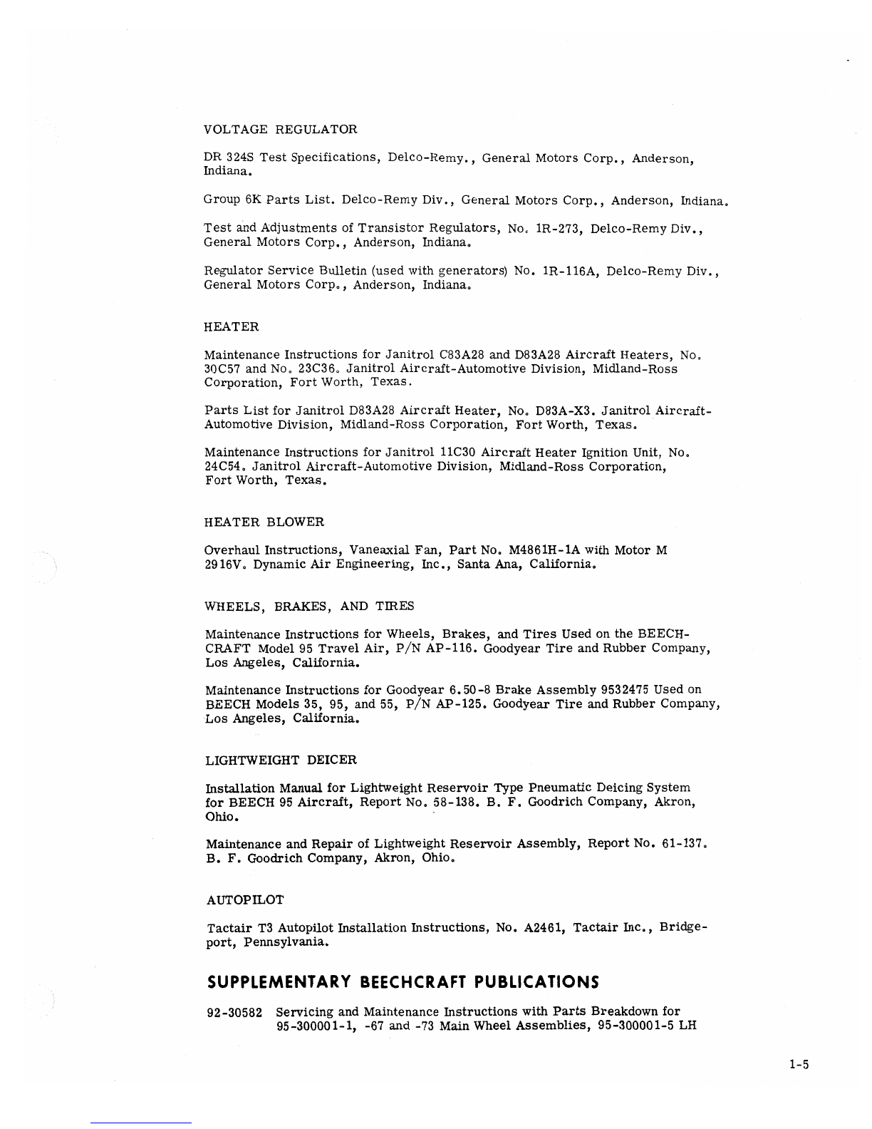
VOLTAGE REGULATOR
DR 324S Test Specifications, Delco-Remy., General Motors Corp., Anderson,
Indiana.
Group 6K Parts List. Delco-Remy Div., General Motors Corp., Anderson, Indiana.
Test and Adjustments of Transistor Regulators, No. 1R-273, Delco-Remy Div.,
General Motors Corp., Anderson, Indiana.
Regulator Service Bulletin (used with generators) No. 1R-116A, Delco-Remy Div.,
General Motors Corp., Anderson, Indiana.
HEATER
Maintenance Instructions for Janitrol C83A28 and D83A28 Aircraft Heaters, No.
30C57 and No. 23C36. Janitrol Aircraft-Automotive Division, Midland-Ross
Corporation, Fort Worth, Texas.
Parts List for Janitrol D83A28 Aircraft Heater, No. DB3A-X3. Janitrol Aircraft-
Automotive Division, Midland-Ross Corporation, Fort Worth, Texas.
Maintenance Instructions for Janitrol 11C30 Aircraft Heater Ignition Unit, No.
24C54. Janitrol Aircraft-Automotive Division, Midland-Ross Corporation,
Fort Worth, Texas.
HEATER BLOWER
Overhaul Instructions, Vaneaxial Fan, Part No. M4861H-1A with Motor M
2916V. Dynamic Air Engineering, Inc., Santa Ana, California.
WHEELS, BRAKES, AND TIRES
Maintenance Instructions for Wheels, Brakes, and Tires Used on the BEECH-
CRAFT Model 95 Travel Air, P/N AP-116. Goodyear Tire and Rubber Company,
Los Angeles, California.
Maintenance Instructions for Goodyear 6.50-8 Brake Assembly 9532475 Used on
BEECH Models 35, 95, and 55, P/N AP-125, Goodyear Tire and Rubber Company,
Los Angeles, California.
LIGHTWEIGHT DEICER
Installation Manual for Lightweight Reservoir Type Pneumatic Deicing System
for BEECH 95 Aircraft, Report No. 58-138. B. F. Goodrich Company, Akron,
Ohio.
Maintenance and Repair of Lightweight Reservoir Assembly, Report No. 61-137.
B. F. Goodrich Company, Akron, Ohio.
AUTOPILOT
Tactair T3 Autopilot Installation Instructions, No. A2461, Tactair Inc., Bridge-
port, Pennsylvania.
SUPPLEMENTARY BEECHCRAFT PUBUCATIONS
92-30582 Servicing and Maintenance Instructions with Parts Breakdown for
95-300001-1, -67 and -73 Main Wheel Assemblies, 95-300001-5 LH
1-5
-6 RH Brake Assemblies, and 95-32669 and 95-32926 Nose Wheel As-
semblies.
98-33281 Servicing and Maintenance Instructions for Goodyear Multi-Disc Brake
Assembly.
130409 Maintenance Instructions for the Beechcraft New-matic Autopilot.
1-6
GENERALINFORMATION
Some of the most important information about the Travel Air .. . lubri-
cation, cleaning, shop handling . . .will be found in this section. Parti-
cular attention should be paid to these items, since they are among the
items which the customer sees and consequently can influence directly
his decision to come back again, or to go elsewhere.
The section includes a three-view drawing giving the major dimensions
of the Travel Air; a table of hangar clearance dimensions; and an access
opening illustration.
Afull-page illustration shows the special tools, with their part numbers,
which will make maintenance of the Travel Air simpler.
2-1
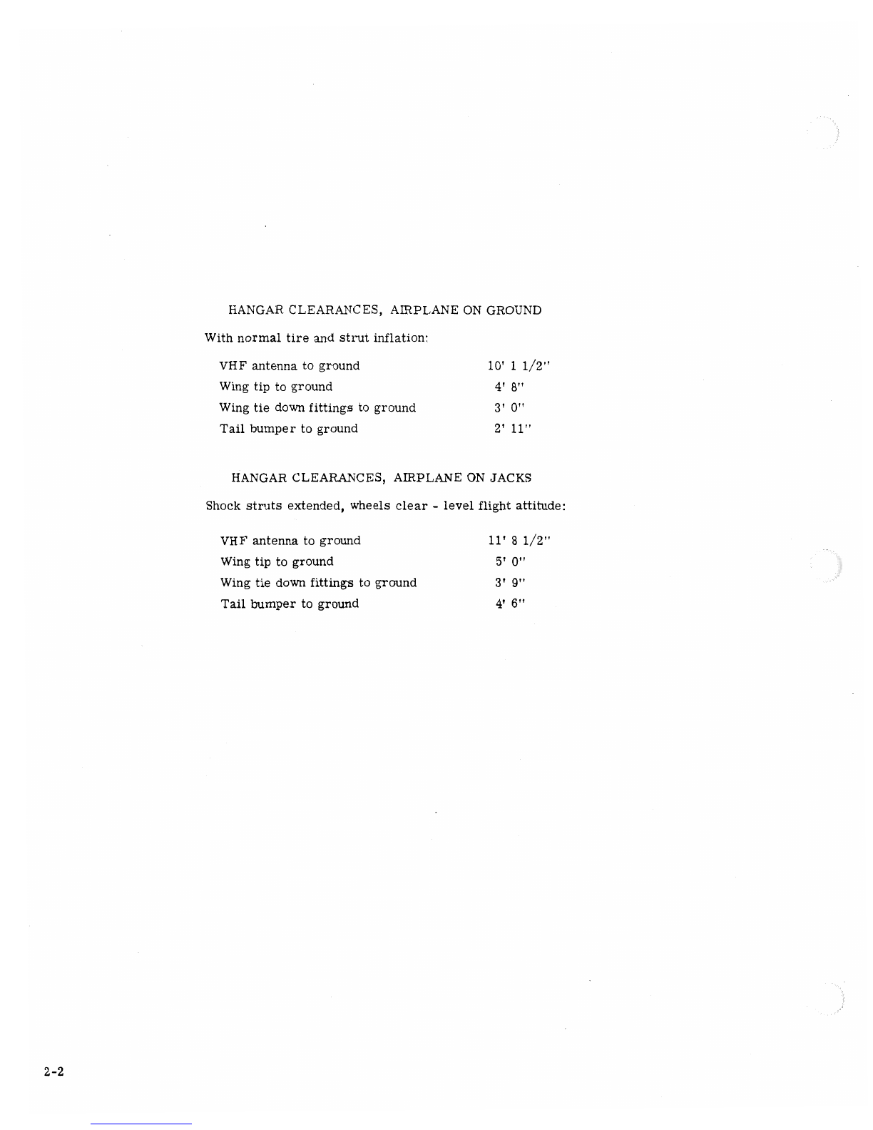
HANGAR CLEARANCES, AIRPLANE ON GROUND
With normal tire and strut inflation:
VHF antenna to ground 10' 11/2"
Wing tip to ground 4' 8"
Wing tie down fittings to ground 3' 0"
Tail bumper to ground 2' 11"
HANGAR CLEARANCES, AIRPLANE ON JACKS
Shock struts extended, wheels clear -level flight attitude:
VHF antenna to ground 11' 81/2"
Wing tip to ground 5' 0"
Wing tie down fittings to ground 3' 9"
Tail bumper to ground 4' 6"
2-2
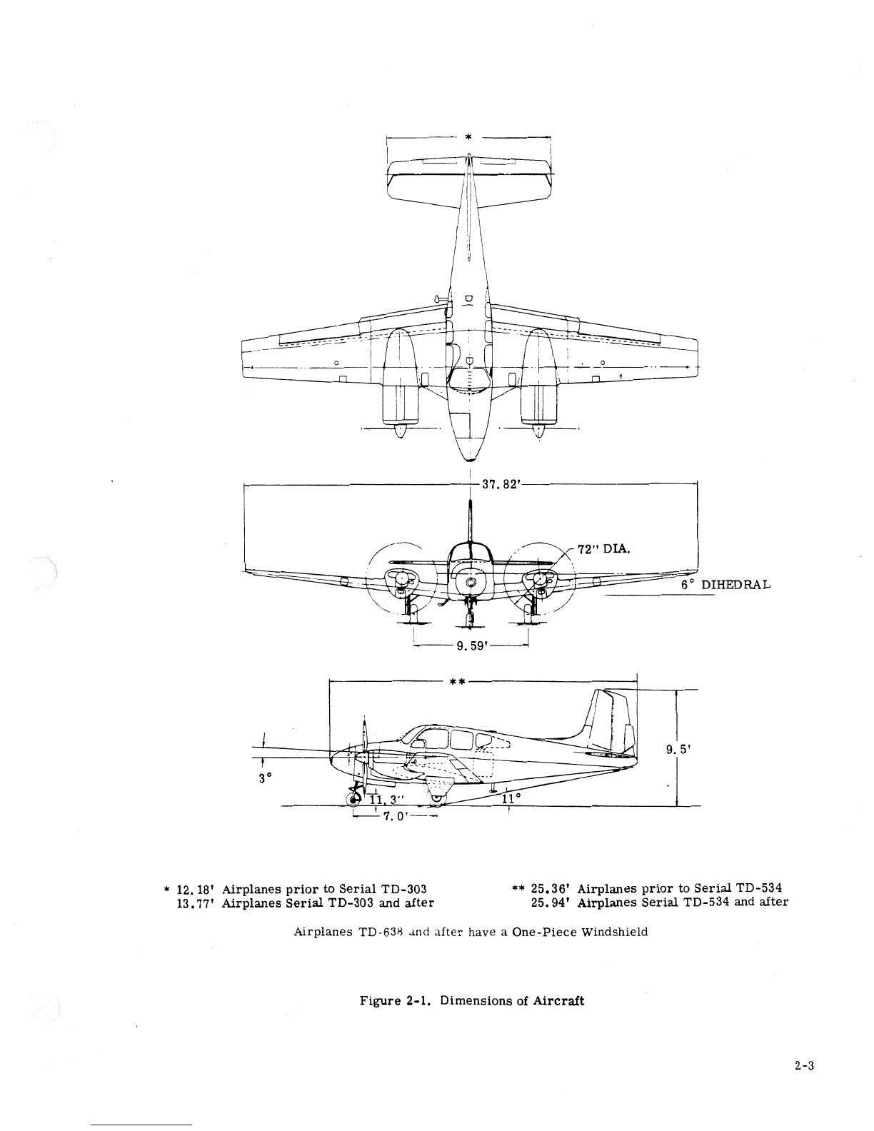
37. 82'
72" DIA.
6° DIHEDRAL
9. 59' I
**
9. 5'
3
I
7. O'
*12. 18' Airplanes prior to Serial TD-303 ** 25.36' Airplanes prior to Serial TD-534
13.77' Airplanes Serial TD-303 and after 25.94' Airplanes Serial TD-534 and after
Airplanes TD-638 and after have aOne-Piece Windshield
Figure 2-1. Dimensions of Aircraft
2-3
0340 47.GOD 34375 23881 82620 66.370 45870 25370 13620
** so34o ao340 as ooo 7e so120 35 s20 is 245
i94 480.047 173 59000 3937
12 500 108 281 83 547- 55 500
222000 198000 175294 148875 129750 |10P3 95463 94094 65000
215000 205 500 191 000 162 5ð3 136 158 113 103 641 300C 00 000
78 049 46270 14 20
41ù20 16320
123 102
HORIZ eeAL TeAB1lLIZER
** *
WING
*** 11000 12000 35250 58500 B4125 107000 213500 257606 272000 15250
-1@000 0000 25250 49000 68000 im oIaM i31000 207000 247830 262© 7263
268610 03885
Note:VER CALnS BILIZER
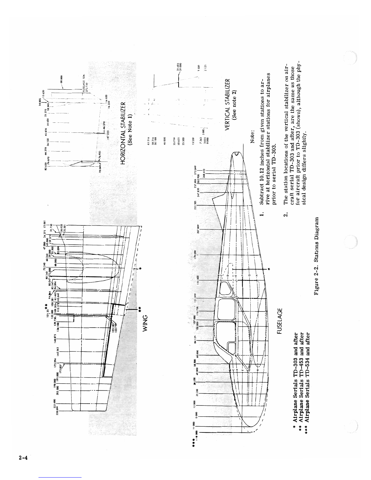
1. Subtract 10.12 inches from given stations to ar-
-- rive at horizontal stabilizer stations for airplanes
prior to serial TD-303.
FUSELAGE 2. The station locations of the vertical stabilizer on air-
craft serial TD-303 and after, are the same as those
*Airplane Serials TD-303 and after for aircraft prior to TD-303 (shown), although the phy-
** Airplane Serials TD-453 and after sical design differs slightly.
*** Airplane Serials TD-534 and after
Figure 2-2. Stations Diagram

*Prior to Airplane Serial TD -303
** Airplane Serial TD -303 and After
2* 16** 16** 2**** Airplane Serial TD-453 and After
22
15**
910 11 3
***
56* 7* 8*
14
1. Elevator trim tab actuator
2. Elevator trim tab actuator sprocket
3. Heater ignition, iris valve and blower assy.
4. Tab actuator, vertical stabilizer
5. Tail cone
6. Rudder bellerank and elevator down spring
7. Elevator bellerank and turnbuckles
8. Cable inspection
9. Landing gear actuator
10. Control cable pulleys and nose gear retract idler arm
11. Hinge bolts for nose wheel strut
12. Rudder tab actuator sprocket
13. Nose baggage door
14. Aft baggage compartment
15. Elevator bellerank, elevator down spring, and turnbuckles
16. Elevator tab cables
17. Horizontal stabilizer mounting bolts
Figure 2-3. Fuselage Access Openings
2-5

33
9 8 7667 8
1516 6
10 11 12
114 15
12 10
123 24 26
26 24 23 21 19 18 18 19 20 22 25
19 19
*25 Gallon Main Fuel Cell is Optional Installation On Airplane Serial TD-453 and After
1. Auxiliary fuel cell filler neck
2. Propeller accumulator, voltage regulator and circuit limiter
3. Oil lever indicator access
4. Main fuel cell filler neck (25-main fuel cell installation optional
TD-453 and after)
5. Main fuel cell transmitter
6. Nacelle inspection plate and access to engine plumbing
7. Auxiliary fuel cell transmitter
8. Aileron bell crank
9. Auxiliary fuel cell transmitter
10. Wing tip spar fitting
11. Auxiliary tank siphon valve
12. Auxiliary tank access
13. Firewall terminal bus (starter relay L. H. only)
14. Engine access
15. Removable cowl nose cap (TD-126 and after)
16. Carburetor air filter
17. Removal wing leading edge cap
18. Wing mounting bolts
19. Flap access
20. Landing gear bolt
21. Aileron cable inspection
22. Aileron cable inspection
23. Alleron cable pully
24. Auxiliary tank access
25. Aileron tab actuator and pully
26. Alleron cable inspection
27. Main fuel cell filler neck (39 or 40-gallon main fuel cell)
28. Main fuel cell transmitter (39 or 40-gallon main fuel cell)
Figure 2-4. Wing Access Openings
2-6

SPECIAL TOOLS
MAIN WHEEL
HOISTING SLING HOISTING SLING ADAPTER SERVICE JACK ADAPTER JACK ADAPTER
95-590016 95-590017 TK 1518 35-590006
AIR FRAME
50-590013 UPPER REAR WING BOLT NUT TORQUE WRENCH ADAPTER
TS 1171-2 UPPER FRONT AND LOWER REAR WING BOLT NUT TORQUE WRENCH ADAPTER
50-590014 FORWARD WING NUT TORQUE WRENCH ADAPTER
TS 1222-1 UPPER FRONT AND LOWER REAR WING BOLT NUT WRENCH
TS 1222-2 UPPER REAR WING BOLT NUT WRENCH
TS 1222-3 UPPER AND LOWER FRONT AND LOWER REAR WING BOLT WRENCH
TS 1222-4 UPPER REAR WING BOLT WRENCH
TC922-2 95910001 PROPELLER TORQUE WRENCH
ADAPTER KIT 300-30
MODEL 300 .-IPi IS TO BE USED WITH
SERVICE JACK ·THE MODEL 300 SERVICE
JACK.
50-590013 TS 1222-3 TS 1222-1 50-590014 TC922-2 95910001
TS 1171-2 TS 1222-4 TS 1222-2
WING
Figure 2-6. Special Tools 2-9
GROUND HANDLING The parking brakes are set by pulling out the parking
brake control and depressing the pilot's brake pedals
JACKING to pressurize the system. Do not attempt to lock the
parking brake by applying force to the parking brake
Two three-point service jacks are available for handle; it controls a valve only, and cannot apply
jacking the aircraft, the Model 300 service jack and pressure to the brake master cylinders.
the Model 35 service jack (TC932 35-000001 equipped
with a95-801 adapter kit for use of the Model 95).
Jack pads are identified and located on the underside iCAUTION)
of the fuselage. One jack pad is located on each lower
wing-to-fuselage attachment fitting along the front Do not set the parking control when
spar. Arear jack pad is located under aprotective the brakes are hot from severe use or
cap in the middle of the fuselage at the rear fuselage during low temperatures when an ac-
carry thru spar. The rear jack fitting screws com- cumulation of moisture may cause the
pletely into the aircraft jack pad. brakes to freeze. Do not leave the
parking brake set for prolonged periods.
HOISTING
Be sure the rear jack point safety pin
is in place to prevent the aircraft from The aircraft may be hoisted for maintenance or parts
nosmg over replacement as follows:
When one engine or one wing is to be removed, aa. Install one 95-590017 hoisting sling adapter on
stand should be placed under the opposite wing and the each forward wing attach bolt,
tail to counteract the resulting unbalanced condition of
the aircraft. Individual main wheels may be jacked
using the special main wheel jack adapter. (See spe- NOTE
cial tools). When hoisting the aircraft with the wings
TOWING removed, replace the 95-590017 sling
adapters with 95-590017-1 sling adapters
and add a95-590016-23 spacer between
Attach the hand towbar to the tow lug on the nose gear each sling adapter and the spar carry
lower torque knee- thru fitting. Install with upper rear wing
CAUTION) attach bolts.
b. Attach the sling assembly, (P/N 95-590016-1), to
When towing with a tug, observe turn the sling adapters.
limits of the nose gear. c. Install the sling strap around the nose, forward
CAUTION) of the nose landing gear.
Do not push on propeller or control d. Hoist the aircraft smoothly.
surfaces. Do not place your weight
on the horizontal stabilizers to raise
the nose wheel off the ground• NOTE
ANCHORING AND MOORING PROVTSIONS Adjust the sling strap to keep the aircraft
Three mooring eyes are provided; one on each wing in a level or slightly nose-down attitude.
and one in the tail bumper. To moor the airplane,
chock the wheels fore and aft, install the control lock
and tie down the aircraft with anylon line or achain LEVELING
of sufficient strength at each mooring eye. Avoid
overtightening the rear line, which pulls up the nose To level the airplane longitudinally, attach acord
so that wind will create higher lift on the wings. If and plumb bob to the Phillips-head screw just above
bad weather is anticipated, it is advisable to nose the the rear baggage compartment door. Inflate or de-
airplane into the wind, flate the nose gear shock strut as necessary to pass
the cord through the center of a second Phillips-head
PARKING BRAKE screw directly below. Suspending the plumb bob in
a can of light engine oil will assist in stabilizing it.
NOTE Lateral leveling is done by putting a bubble level on the
Use of the parking brake is not rec- rear baggage compartment floorboard and deflating
ommended when wheel chocks and/or the tire or strut on the high side of the airplane to
tie down facilities are available, center the bubble.
2-10
This manual suits for next models
4
Table of contents
Other Beechcraft Aircraft manuals

Beechcraft
Beechcraft Baron B55 User manual

Beechcraft
Beechcraft BE76 Duchess User manual

Beechcraft
Beechcraft KING AIR C90 Owner's manual

Beechcraft
Beechcraft Bonanza V35B-TC User manual

Beechcraft
Beechcraft Baron 58 Owner's manual

Beechcraft
Beechcraft Bonanza V35B Owner's manual

Beechcraft
Beechcraft Duke 60 Series User manual

Beechcraft
Beechcraft Baron G58 Owner's manual

Beechcraft
Beechcraft C-12C Use and care manual

Beechcraft
Beechcraft C23 SUNDOWNER 180 Owner's manual


