Beechcraft Bonanza V35B-TC User manual

NLJ
ech Gircrah nr pnration

OWNER'S MANUAL
SUPPLEMENT
for
K35, M35, N35,'P35, S35, V35, V35TC, V35A, V35A TC, V3SB, V35B TC
33, A33, B33, C33, E33, F33, G33, C33A, E33A, F33A, 36, A36.
The following information supersedes the information contained in the
Owner's Manuals for the above listed airplanes.
1. Maximum usable fuel of each 25 or 24½gallon main tank is 22
gallons.
2. Maximum usable fuel of each 39 or 40 gallon main tank is 37 gallons.
3. Approximate reduction in range with full fuel due to change in usable
fuel is:
a. 13%on 22 gallon main tank system.
b. 9% on 37 gallon main tank system.
4. On Models K-35, M-35, 33, and A33 Owners Manuals, reduce range by
an additional 190 statute miles to account for climb and 45 minutes
reserve at 45% maximum continuous power.
P/N 35-590118-17 Issued:February 11, 1972
THANK YOU ...
for displaying your confidence in us by selecting a BEECHCRAFT
airplane. Our design engineers, assemblers, and inspectors have utilized
their skills to ensure that your new BEECHCRAFT Bonanza V35B-TC
excels all other airplanes in its class in structural integrity, performance,
workmanship, economy, and comfort.
IMPORT ANT NOTICE
This manual should be read carefully in order that you may
become familiar with the operation of your Bonanza V35B-TC.
Suggestions and recommendations have been made within it to
help you obtain maximum performance without sacrificing
economy. Furthermore, you should also be familiar with and
operate your new BEECHCRAFT in accordance with the Federal
Aviation Administration Approved Flight Manual and/or the
FAA Approved Placards which are located in your
BEECHCRAFT.
As a further reminder, you should also be familiar with the applicable
Federal Aviation Regulations concerning operation and maintenance of
the airplane and FAR Par 91 General Operating and Flight Rules.
Likewise your aircraft must be operated and maintained in accordance
with FAA Airworthiness Directives which may be issued against your
BEECHCRAFT.
The operation, care, and maintenance of your airplane after it is
delivered to you is your responsibility. However, your authorized
BEECHCRAFT Sales & Service Outlets will have all recommended
modification, service, and operating procedures issued by both FAA
and Beech, designed to get maximum utility and safety from your
airplane.
In an effort to provide you with as complete coverage as possible,
applicable to any configuration of the Bonanza V35B-TC, optional
equipment has been included in the scope of this manual. Because of
the versatility of the appointments and arrangements of the aircraft, the
equipment described or depicted herein may not be designated as
optional equipment in every case.
35-590118-7 Issued: November 6, 1969

LIST OF EFFECTIVE PAGES
INTRODUCTION
List of Effective Pages
i through iii
1-1 through 1-21
2-1 through 2-6
3-1 through 3-7
4-1 through 4- 6
5-1 through 5- 7
6-1 through 6-21
7-1 through 7-9
8-1 through 8-3 I
A Bonanza V358-TC
Original
Original
Original
Original
Original
Original
Original
Original
Original
Original
Original

TABLE OF CONTENTS
SECTION I Description and Operation of Systems . 1-1
SECTION II Operating Check Lists . 2-1
SECTION Ill Normal Procedures . 3-1
SECTION IV Emergency Procedures .4-1
SECTION V Limitations . 5-1
SECTION VI Performance . 6-1
SECTION VII Optional Equipment . 7-1
SECTION VIII Servicing . 8-1
Turbo-Bonanza V35B-TC
35-590118-7*2
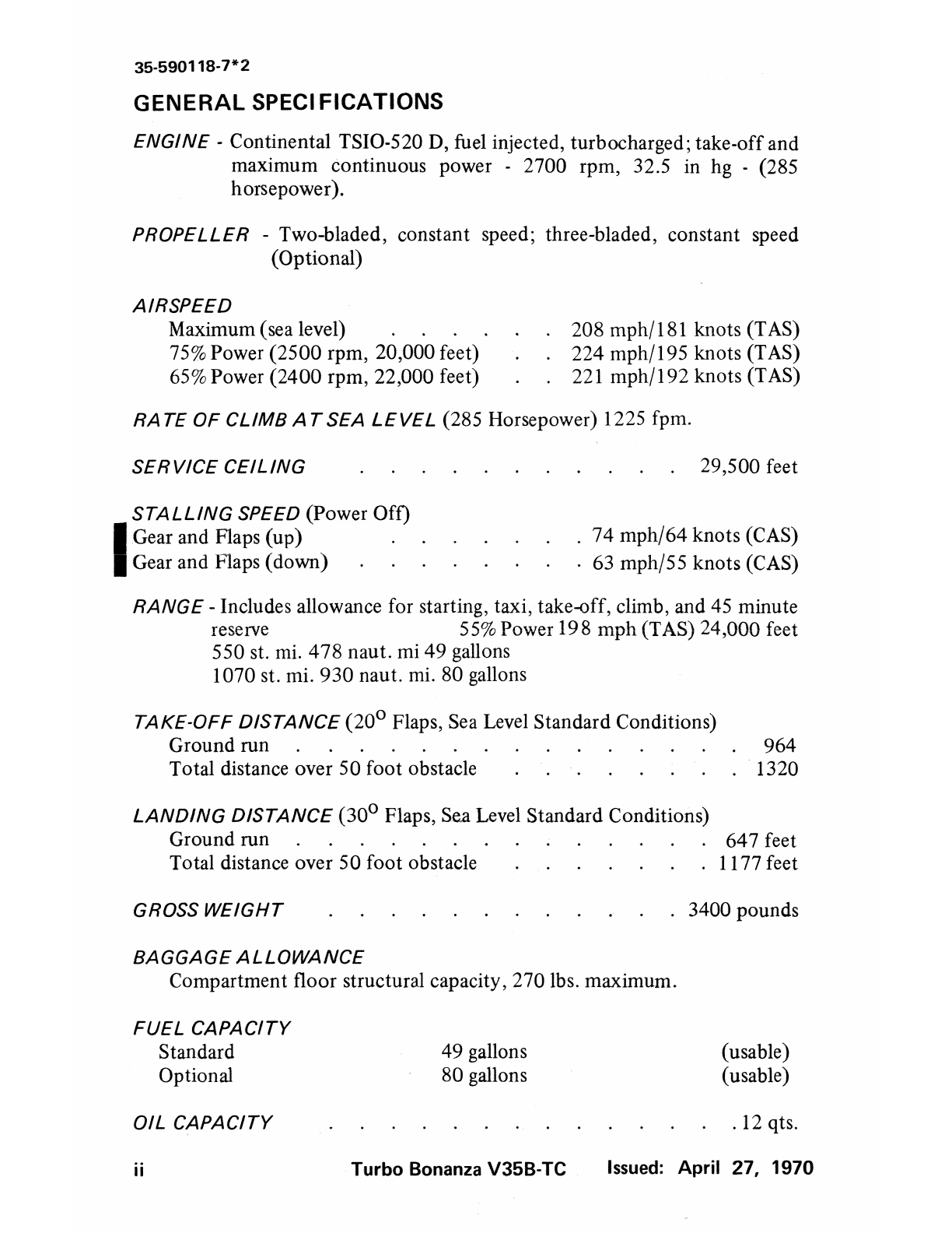
GENERAL SPECIFICATIONS
ENGINE· Continental TSI0-520 D, fuel injected, turbocharged; take-off and
maximum continuous power - 2700 rpm, 32.5 in hg - (285
horsepower).
PROPELLER -Two-bladed, constant speed; three-bladed, constant speed
(Optional)
AIRSPEED
Maximum (sea level)
75%Power (2500 rpm, 20,000 feet)
65%Power (2400 rpm, 22,000 feet)
208 mph/181 knots (TAS)
224 mph/195 knots (TAS)
221 mph/192 knots (TAS)
RA TE OF CLIMB AT SEA LEVEL (285 Horsepower) 1225 fpm.
SERVICE CEILING 29,500 feet
STALLING SPEED (Power Off)
I
Gear and Flaps (up) .
Gear and Flaps (down) . .
. 74 mph/64 knots (CAS)
. 63 mph/55 knots (CAS)
RANGE -Includes allowance for starting, taxi, take-off, climb, and 45 minute
reserve 55%Power 198 mph (TAS)24,000 feet
550 st. mi. 478 naut. mi 49 gallons
1070 st. mi. 930 naut. mi. 80 gallons
TAKE-OFF DISTANCE (20° Flaps, Sea LevelStandard Conditions)
Ground run 964
Total distance over 50 foot obstacle · 1320
LANDING DISTANCE (30° Flaps, Sea Level Standard Conditions)
Ground run 647 feet
Total distance over 50 foot obstacle . 1177 feet
GROSSWEIGHT
BAGGAGE ALLOWANCE
3400 pounds
Compartment floor structural capacity, 270 lbs. maximum.
FUEL CAPACITY
Standard
Optional
OIL CAPACITY
ii
49 gallons
80 gallons
Turbo Bonanza V358-TC
(usable)
(usable)
.12 qts.
Issued: April 27, 1970

7' 7"
91 7. l"---1
---------33' 5. 5"---------.;
Turbo-Bonanza V35B-TC iii
SECTION I
DESCRIPTIONAND OPERATIONOF SYSTEMS
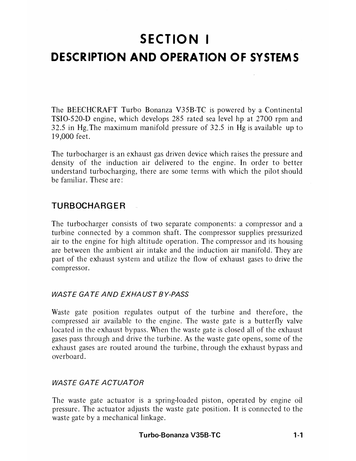
The BEECHCRAFT Turbo Bonanza V35B-TC is powered by a Continental
TSI0-520-D engine, which develops 285 rated sea level hp at 2700 rpm and
32.5 in Hg.The maximum manifold pressure of 32.5 in Hg is available up to
19,000 feet.
The turbocharger is an exhaust gas driven device which raises the pressure and
density of the induction air delivered to the engine. In order to better
understand turbocharging, there are some terms with which the pilot should
be familiar. These are:
TURBOCHARGER
The turbocharger consists of two separate components: a compressor and a
turbine connected by a common shaft. The compressor supplies pressurized
air to the engine for high altitude operation. The compressor and its housing
are between the ambient air intake and the induction air manifold. They are
part of the exhaust system and utilize the t1ow of exhaust gases to drive the
compressor.
WASTE GA TE AND EXHAUST BY-PASS
Waste gate position regulates output of the turbine and therefore, the
compressed air available to the engine. The waste gate is a butterfly valve
located in the exhaust bypass. When the waste gate is closed all of the exhaust
gases pass through and drive the turbine. As the waste gate opens, some of the
exhaust gases are routed around the turbine, through the exhaust bypass and
overboard.
WASTE GATE ACTUATOR
The waste gate actuator is a spring-loaded piston, operated by engine oil
pressure. The actuator adjusts the waste gate position. It is connected to the
waste gate by a mechanical linkage.
Turbo-Bonanza V35B-TC 1-1
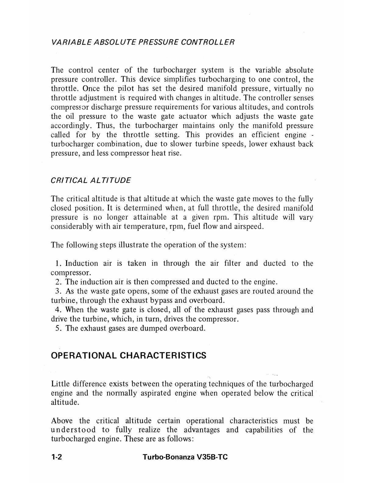
VARIABLE ABSOLUTE PRESSURE CONTROLLER
The control center of the turbocharger system is the variable absolute
pressure controller. This device simplifies turbocharging to one control, the
throttle. Once the pilot has set the desired manifold pressure, virtually no
throttle adjustment is required with changes in altitude. The controller senses
compress Grdischarge pressure requirements for various altitudes, and controls
the oil pressure to the waste gate actuator which adjusts the waste gate
accordingly. Thus, the turbocharger maintains only the manifold pressure
called for by the throttle setting. This provides an efficient engine .
turbocharger combination, due to slower turbine speeds, lower exhaust back
pressure, and less compressor heat rise.
CRITICAL ALTITUDE
The critical altitude is that altitude at which the waste gate moves to the fully
closed position. It is determined when, at full throttle, the desired manifold
pressure is no longer attainable at a given rpm. This altitude will vary
considerably with air temperature, rpm, fuel flow and airspeed.
The following steps illustrate the operation of the system:
1. Induction air is taken in through the air filter and ducted to the
compressor.
2. The induction air is then compressed and ducted to the engine.
3. As the waste gate opens, some of the exhaust gases are routed around the
turbine, through the exhaust bypass and overboard.
4. When the waste gate is closed, all of the exhaust gases pass through and
drive the turbine, which, in turn, drives the compressor.
5. The exhaust gases are dumped overboard.
OPERATIONAL CHARACTERISTICS
Little difference exists between the operating techniques of the turbocharged
engine and the normally aspirated engine when operated below the critical
altitude.
Above the critical altitude certain operational characteristics must be
understood to fully realize the advantages and capabilities of the
turbocharged engine. These are as follows:
1-2 Turbo-Bonanza V35B-TC
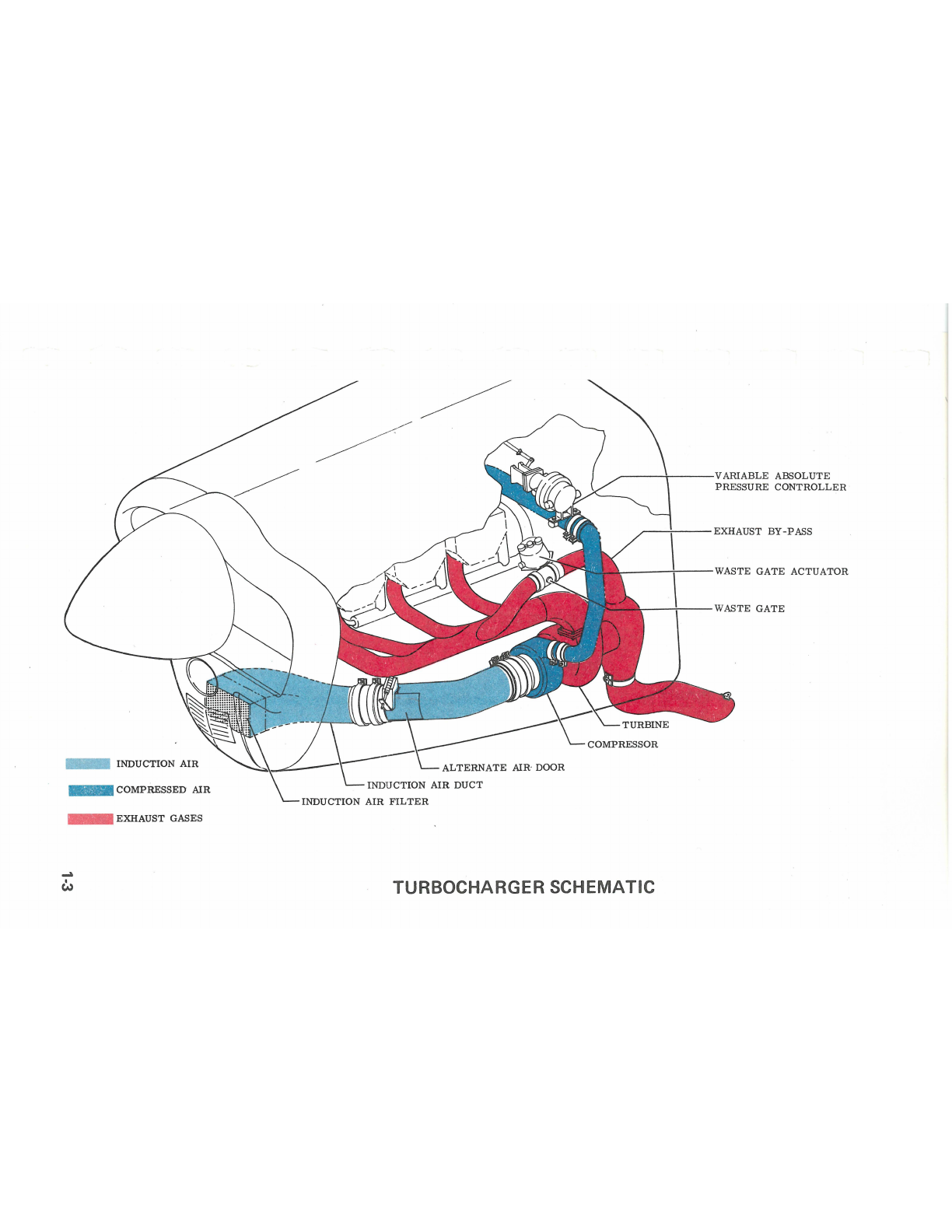
- INDUCTION AIR
- COMPRESSED AIR
- EXHAUST GASES
...
c:.,
ALTERNATE AIR DOOR
,,.------------ VARIABLE ABSOLUTE
PRESSURE CONTROLLER
----'---EXHAUST BY-PASS
-----;\,--- WASTE GATE ACTUATOR
, WASTE GATE
TURBOCHARGER SCHEMAT IC
RPM EFFECT ON MANIFOLD PRESSURE
Above the critical altitude, any change in rpm will result in a like change in
manifold pressure. If, on a hot day with full throttle, the desired percent of
power is unattainable for a given rpm, a slight increase in rpm will produce a
significant increase in manifold pressure.
FUEL FLOW EFFECT ON MANIFOLD PRESSURE
Above the critical altitude, with rpm and manifold pressure established for
cruise, leaning will cause a slight increase in manifold pressure. When the
mixture reaches the recommended fuel flow, a slight reduction in manifold
pressure may be necessary.
AIRSPEED EFFECT ON MANIFOLD PRESSURE
Above the critical altitude, any change in airspeed will result in a
corresponding change in manifold pressure. This is true because the increase
in ram air pressure, with an increase in airspeed, is magnified by the
compressor resulting in an increase in manifold pressure. The increase in
manifold pressure creates a higher mass flow through the engine, causing
higher turbine speeds and thus further increasing manifold pressure. This
characteristic may be used to best advantage by allowing the aircraft to
accelerate to cruise speed after leveling off and prior to reducing power.
ENGINE RESPONSE AT HIGH ALTITUDE
Response from normal cruise power to maximum power is nearly
instantaneous at high altitude. In the event the engine is idled, it may be
necessary to lean the mixture, after application of partial throttle, to regain
the turbocharger speed.
EFFECT OF AMBIENT TEMPERATURE ON POWER
The V35B-TC engine will vary its power 1% for every 6°F above or below
standard day temperatures. An increase in temperature will result in a
decrease in power. To attain a given percent of power will then require
increases in manifold pressure with increases in ambient temperature. For
power settings, refer to the Horsepower Settings Chart in Section VI.
1-4 Turbo-Bonanza V35B-TC
CAUTION
The engine manufacturer limits the manifold pressure to
32.5 in Hg.Particular care should be taken in cold weather
when operating with cold oil to avoid exceeding this
limitation. The last 1 - 1/2 inches of throttle travel should
be applied slowly while monitoring the manifold pressure
gage.
FLIGHT CONTROLS
Control surfaces are operated through push-pull rods and conventional cable
systems terminating in bellcranks. The preformed steel cables run over
phenolic pulleys, to minimize wear.
CONTROL COLUMN
The throw-over type control column for elevator and aileron control can be
placed in front of either front seat. Pull the I-handle latch at the base of the
control arm and position the control column as desired. The aileron trimmer
on the control column hub should be held until the column is repositioned.
RUDDER PEDALS
To adjust the rudder pedals, press the spring-loaded lever on each pedal arm
and move the pedal forward or aft. The adjustment lever can also be used to
place the right-hand set of rudder pedals against the floor when not in use.
TRIM CONTROLS
Elevator trim is controlled by a handwheel located to the left of the throttle.
An elevator tab indicator dial is located above and to the left of the trim
control handwheel.
The aileron trimmer on the control column hub displaces the ailerons:
displacement is maintained by cable loads imposed by the trimmer.
WING FLAPS
The wing flaps are controlled by a three-position switch, UP, OFF and
DOWN, located in the subpanel, above the power quadrant. The switch
Turbo-Bonanza V35B-TC 1-5

must be pulled out of detent before it can be repositioned. A dial type
indicator has markings for UP, JO DEGREES, 20 DEGREES and DOWN. The
indicator is located to the left of the control column.
Limit switches automatically turn off the electrical motor when the flaps
reach the extremes of travel. Intermediate flap positions can be obtained by
placing the three-position switch in the OFF position during flap extension or
retraction.
POWER PLANT CONTROLS
THROTTLE, PROPELLER, AND MIXTURE
The push-pull throttle, propeller, and mixture controls are located on the
control console below the center of the subpanel. Each control is released for
repositioning by pushing a button on the knob. With the control secured, fine
adjustments are accomplished by rotating the knob.
if oil pressure is lost, the propeller will go to the full low pitch (high rpm)
position. This is because propeller high pitch (low rpm) is obtained by
governor boosted engine oil pressure working against the centrifugal twisting
movement of the blades.
ALTERNATE AIR
A pull-and-release handle below the propeller control can be used to force
open the alternate air source door in the air intake duct, should the door
become frozen shut. (See Induction System Icing, Section III.)
COWL FLAPS
The forward cowl flaps push-pull control is located directly below the
propeller control. These flaps are to be used as necessary to control engine
temperature with the rear cowl flaps open.
The rear cowl flaps push pull control is located above and to the left of the
throttle control. These flaps are to be open for take-off and climb, closed for
cruise.
1-6 Turbo-Bonanza V358-TC
COWLING
The Bonanza V35B-TC is equipped with Hartwell latch mechanisms on the
right and left upper engine cowling for quick and easy access to the engine
compartments without the aid of tools. Each cowl latch is locked and
released by a single, recessed handle located in the lower cowlmg panel on
each side of the engine. To close the cowling requires only to lower the
cowling to the closed position with the handle in the precatch position. The
handle has three positions; flush with the fuselage • latched: Held fully
forward - unlatch (Open Cowling); Approximately 9rP to the fuselage -
precatch (ready to close cowl). An audible click denotes the bayonet fittings,
located forward and aft on the upper cowl, sliding into the latch safety catch.
The cowl is locked by moving the latch handle to the full recessed position.
The security of the forward latches can be checked by pulling out on the
check tab attached to the lower forward edge of the upper cowling. If the
cowling can be moved after latching, open the cowling and check the latch
alignment and re-latch.
LANDING GEAR SYSTEM
CONTROL SWITCH
The landing gear is controlled by a two-position switch on the right side of
the subpanel. The switch handle must be pulled out of the safety detent
before it can be moved to the opposite position.
POSITION IND/CA TORS
The landing gear position indicator lights are located adjacent to the landing
gear switch handle. Three green lights, one for each gear, are illuminated
whenever the landing gears are "down and locked". The red light illuminates
any time one or all of the landing gears are in transit or in any intermediate
position. All of the lights will be out when the gears are up and locked. The
nose gear also has a mechanical pointer, located at the base of the pedcstaL
which gives the positive position of the nose gear at all times. Pressing the
warning light test button on the instrument panel will verify the landing gear
lamp bulbs are illuminating. The intensity of the lamps are automatically
lowered for night flights when the navigation lights are turned on.
SAFETY SWITCH
To prevent inadvertent retraction of the landing gear on the ground, a safety
switch on the right hand main strut opens the control circuit when the strut is
compressed.
Turbo-Bonanza V35B-TC 1-7

CAUTION
Never rely on the safety switch to keep the gear down
during taxi or on take-off or landing roll. Always make
certain that the landing gear switch is in the down position
during these operations.
WARNING HORN
With the landing gear retracted, if the throttle is retarded below
approximately 12 in Hg manifold pressure, a warning horn on the cabin
forward bulkhead will sound intermittently.
CIRCUIT BREAKER
The landing gear circuit breaker is located on the right hand subpanel. This
circuit breaker is the only pull and reset type breaker on the panel. The
breaker will pop-out under overload conditions.
MANUAL EXTENSION
The landing gear can be manually extended by operating a handcrank at the
rear of the front seats. This procedure is described in Section IV.
BRAKES
The brakes on the main landing gear wheels are operated by applying toe
pressure to the rudder pedals. The parking brake push-pull control is located
on the left side of the lower subpanel. To set the parking brakes, pull the
control out and pump each toe pedal until solid resistance is felt. Push the
control in to release the brakes.
1-8
NOTE
The parking brake should be left off and wheel chocks
installed if the airplane is to be left unattended. Changesin
ambient temperature can cause the brakes to release or to
exert excessive pressures.
Turbo-Bonanza V35B-TC
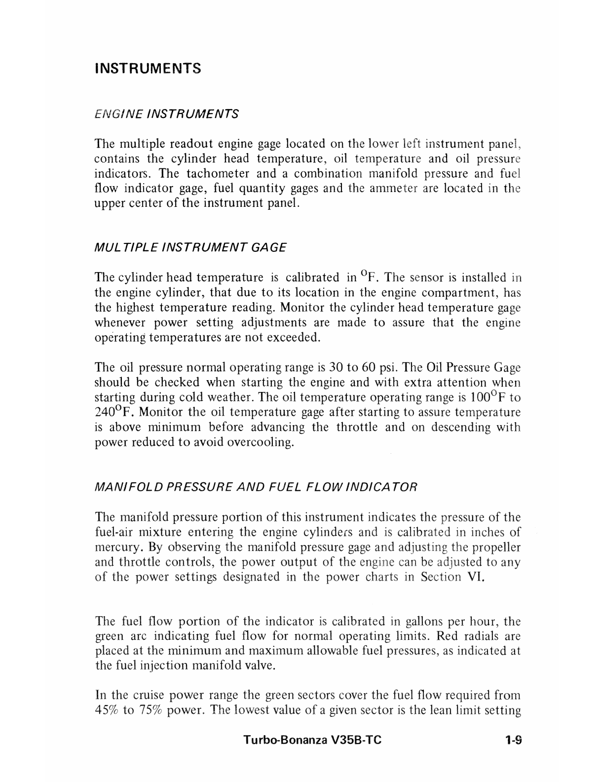
INSTRUMENTS
ENGINE INSTRUMENTS
The multiple readout engine gage located on the lower left instrument panel,
contains the cylinder head temperature, oil temperature and oil pressure
indicators. The tachometer and a combination manifold pressure and fuel
flow indicator gage, fuel quantity gages and the ammeter are located in the
upper center of the instrument panel.
MUL TJPLE INSTRUMENT GAGE
The cylinder head temperature is calibrated in °F. The sensor is installed in
the engine cylinder, that due to its location in the engine compartment, has
the highest temperature reading. Monitor the cylinder head temperature gage
whenever power setting adjustments are made to assure that the engine
operating temperatures are not exceeded.
The oil pressure normal operating range is 30 to 60 psi. The Oil Pressure Gage
should be checked when starting the engine and with extra attention when
starting during cold weather. The oil temperature operating range is Ioo°Fto
240°F. Monitor the oil temperature gage after starting to assure temperature
is above minimum before advancing the throttle and on descending with
power reduced to avoid overcooling.
MANIFOLD PRESSURE AND FUEL FLOW INDICATOR
The manifold pressure portion of this instrument indicates the pressure of the
fuel-air mixture entering the engine cylinders and is calibrated in inches of
mercury. By observing the manifold pressure gage and adjusting the propeller
and throttle controls, the power output of the can be adjusted to any
of the power settings designated in the power charts in Section VI.
The fuel flow portion of the indicator is calibrated in gallons per hour, the
green arc indicating fuel flow for normal operating limits. Red radials are
placed at the minimum and maximum allowable fuel pressures, as indicated at
the fuel injection manifold valve.
In the cruise power range the green sectors cover the fuel flow required from
45% to 75% power. The lowest value of a given sector is the lean limit setting
Turbo-Bonanza V35B-TC 1-9

1-10
\J
Ci)
~:
' 'O
000
and the highest value of the sector is the best-power setting for that particular
power range.
The take-off and climb range is covered by green sectors for full power at
various altitudes. The full power markings represent the maximum
performance mixtures for the altitudes shown, permitting leaning of the
mixture for maximum power and performance during high altitude take-offs
and full power climbs.
FUEL SYSTEM
The aircraft is designed for operation on 100/130 grade aviation gasoline. In
the event this grade is not available only a higher rated fuel shall be used.
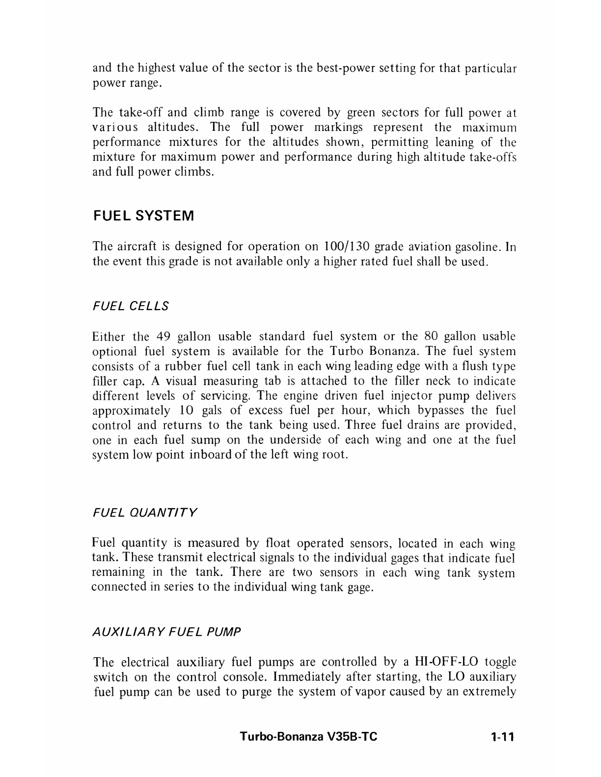
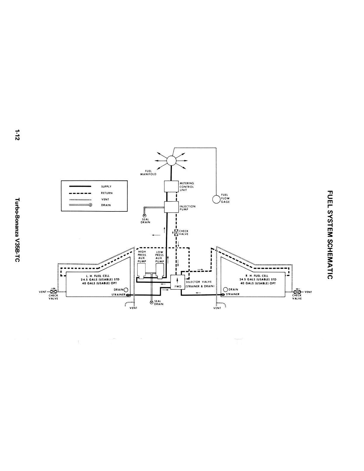
FUEL CELLS
Either the 49 gallon usable standard fuel system or the 80 gallon usable
optional fuel system is available for the Turbo Bonanza. The fuel system
consists of a rubber fuel cell tank in each wing leading edge with a flush type
filler cap. A visual measuring tab is attached to the filler neck to indicate
different levels of servicing. The engine driven fuel injector pump delivers
approximately 10 gals of excess fuel per hour, which bypasses the fuel
control and returns to the tank being used. Three fuel drains are provided,
one in each fuel sump on the underside of each wing and one at the fuel
system low point inboard of the left wing root.
FUEL QUANTITY
Fuel quantity is measured by float operated sensors, located in each wing
tank. These transmit electrical signalsto the individual gagesthat indicate fuel
remaining in the tank. There are two sensors in each wing tank system
connected in series to the individual wing tank gage.
AUXILIARY FUEL PUMP
The electrical auxiliary fuel pumps are controlled by a HI-OFF-LO toggle
switch on the control console. Immediately after starting, the LO auxiliary
fuel pump can be used to purge the system of vapor caused by an extremely
Turbo-BonanzaV35B-TC 1-11
...
.
...
N
I
i
!t
n
===@
SUPPLY
RETURN
VENT
DRAIN
SUL
DRAIN
I
I
I
I
• IQ!CHECK
~VALVE
I
FUEL
FLOW
GAGE
Ii
,,,••':---- -- __ , - -:· - - .. .....=••,,,,,
,,,,,,,.-I HIGH LOW I I I , .....,,,,,,,,
,,,,,, # _. : PRESS. PRESS. I I : ._.._, ,,,,,,
,,,••··~-- : AUX. AUX I I I ; ...., ..,,,,,
,,,,,,,.,, - :; PUMP PUMP lj I : --.,..._ ,,,,,,,
;: 111111 11u1111111111111111uu11111u•' (/1, E I I ! ......._ '•••11111111111111111111111111111111111:
E·------------ ; I : - I i ...,_________ , i
: I ,-------' : _______ .. : "--------, I :
i • L. H. FUELCELL i l'LJ" __ ....__,_ I i I. H. FUELCELL • i
: 24.5 GALS (USAIU) STD i ---1+---~ .I : 24.5 GALS (USAILE) STD (
40 GALS tUSAILE) OPT i re-::-,_ _ __.(:~~~~~~: &V~~~~N) i 40 GALS (USAlf.E) 0'1
VENt111L81,tu111 DRAINQ i - i QoRAIN ,... Jcii,.11,VENT
CHECK STRAINER : : STl:AINElt CHECK
VALVE i i VALVE
.. SEAL :
!1111111 ~ DRAIN :' 11111 •• ..
.. veNt vENt =
.,,
C:
m
r-
(1)
m
31:
::t
m
31:
C')
high ambient temperature or a start with the engine hot. LO boost should
also be used during the climb above 8000 feet and at high altitude cruise, if
required to stabilize fuel flow. HI boost provides for near maximum engine
performance should the engine driven pump fail.
FUEL TANK SELECTION
The fuel selector valve handle is located forward and to the left of the pilot's
seat. Ordinarily, take-offs and landing should be made using the cell that is
more nearly full.
If the engine is allowed to stop firing, due to insufficient fuel it is important
that the following procedure be observed.
I. Retard the throttle to prevent an engine overspeed condition.
2. Mixture - FULL RICH.
3. Switch to the other cell, visually checking the fuel selector valve.
4. Turn the auxiliary fuel pump to the LO position until power is regained.
5. Advance the throttle to the desired position.
OIL SYSTEM
The engine oil system is the full-pressure, wet sump type and has a 12-quart
capacity. Oil operating temperatures are controlled by an automatic
thermostat bypass control. The bypass control will limit oil flow through the
oil cooler when operating temperatures are below normal and will permit the
oil to bypass the cooler if it should become blocked. A full-flow, integrally
mounted oil filter is provided. See Section VIII for servicing procedures.
ELECTRICAL SYSTEM
The system circuitry is the single wire, ground return type, with the aircraft
structure used as the ground return. The battery OFF-ON switch, the
alternator OFF-ON switch and the key lock start switch are located on the
left subpanel. The circuit breaker panel is located on the right subpanel and
contains the protective circuit breakers for the various electrical systems.
Some switch type circuit breakers are located on the left subpanel.
BATTERY
A 33 ampere hour, 12-volt battery is located on the right hand forward side
of the firewall. Battery servicingprocedures are described in Section VIII.
Turbo-Bonanza V35B-TC 1-13
Table of contents
Other Beechcraft Aircraft manuals

Beechcraft
Beechcraft BE76 Duchess User manual

Beechcraft
Beechcraft Duke 60 Series User manual

Beechcraft
Beechcraft KING AIR C90 Owner's manual

Beechcraft
Beechcraft Baron B55 User manual

Beechcraft
Beechcraft Baron 58 Owner's manual

Beechcraft
Beechcraft C-12C Use and care manual

Beechcraft
Beechcraft Debonair C33 User manual

Beechcraft
Beechcraft Debonair 35-33 Owner's manual

Beechcraft
Beechcraft C23 SUNDOWNER 180 Owner's manual

Beechcraft
Beechcraft Bonanza 36 Owner's manual


