Beechcraft Baron B55 User manual

Military Visualizations Beechcraft® Baron® B55 Quick Start Guide
Here it is! The bare bones! The “kick the tires and light the fires and get airborne guide.”
You read this and you get off the ground. You want to
learn how the airplane actually works and flies properly,
then you read the Pilot’s Operating Handbook (POH)
when you feel like it.
Step one: You have booted up FSX in Free Flight and
you’re sitting in the cockpit. On the keyboard, press Shift-
1 to bring up the setup menu box (figure 1). If you
want a two-blade prop, click the “Swap Props” button Figure 1
red. You want three blades again, click it green! You want to remove the chocks, click that
button. Click it again to bring them back. You want the pilot visible and the engine plugs and
pitot covers removed, then click that button to make it green. Want the pilot gone and the
plugs and covers back, click it red.
Step two: You want to light the fire! OK, here’s how:
1. On the left side of the cockpit, beside the yoke, see that box (figure 2)? It has your starter
buttons, master battery switch, and left/right
alternator switches. See the triangular arrayed
switches (figure 3)? The top of the triangle is the
master battery. The two base switches are the left
and right alternator switches. Flip all three up to the
on positions.
Figure 2
2. Look in the center of the panel, see those six levers? The two in the middle are your
throttles –that’s right Beech put the throttles for the Baron 55 in the middle! Use your
keyboard, mouse, or your physical controllers and push those two throttles forward about a
half inch forward from the full aft position. Make sure your two prop control levers are full
forward and the two mixture levers are full forward.
3. See that huge yoke? Covers up near everything doesn’t it? Let’s hide it temporarily!
See the bare aluminum shaft that pierces the panel in the center? Hover your mouse pointer
Figure 3
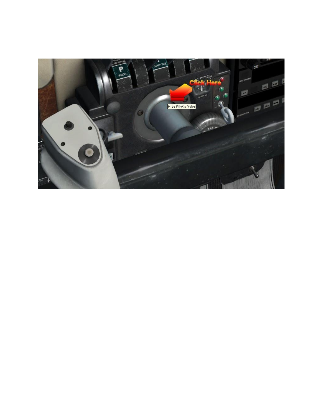
over the base where it pierces the panel and click it (figure 4). You want the yoke back? Click
that open hole and it comes back. Now that it’s hidden, we can see our way to the rest.
Figure 4
4. Reference the pilot’s lower panel with all those switches in a long row (figure 5). In the
center, there is one labeled “Beacon.” You should click it up to the on position. This turns on
the rotating red beacon light and warns people you’re about to turn on the engines. It is
ultimately the “Get out of the way or forever lose your head” warning!

Figure 5
Once the engines are started, and you have confirmed power is supplied by the alternators
(referencing the two load meters) you should turn on the rest of your lights. To learn more
about the details, plus also how to use the two auxiliary fuel pumps, please
read the POH.
5. Take another look at that left console panel (figure 2). See the two
vertically arrayed knobs (figure 6)? Those knobs perform two integrated
functions. They are starters as well as magneto switches. The top knob
controls the left engine and the bottom one controls the right engine. They
rotate clockwise and counter-clockwise by using your mouse to hover over
the knobs, click and hold the left mouse button, and slide the mouse right or
Figure 6 left to rotate the knobs. The starter is engaged when you rotate the knob
full clockwise. When you release the left mouse button the knob returns to the BOTH position
which activates the two magnetos.
Rotate those two starter/mag knobs to crank both engines. When you want to learn to check
the individual magnetos, you use those same knobs and rotate
them counter-clockwise to isolate the right and left mags for each
engine (note the “R” and “L” labels). When both engines are
started, then you are ready to proceed to the next step.
Figure 7
Step three: Turn on the rest of your lights and your avionics on the radio stack. To turn on the
avionics, reference the left side of the pilot’s panel and you will see one lone switch labeled
“Radio Master” (figure 7). This is your avionics master switch labeled in the style things were
named back in the era this aircraft was constructed. Once you toggle this switch on you should
see the avionics on the radio stack turn on. To operate the two Garmin GPS/Moving Map
Comm/Nav radio units, you must read the separate manuals provided in your aircraft’s folder in
FSX.
Step four: Now you are ready to taxi. You should know how to use the FSX menus for radio
interaction and control. So, do what you need to do to taxi to the runway. Line up for takeoff
and apply brakes. Throttle up to 2100 RPM’s with the brakes applied and reference your
engine instruments (on the far right side of the pilot’s panel – yep they are just that
conveniently located in the real airplane also!). If all looks good, release the brakes and
smoothly apply full power. Note: the plane will require significant degrees of rudder inputs to
maintain runway centerline. This is how it really is. How do you learn to do it accurately and
keep on centerline? Three words: Practice, Practice, Practice!
Step five: See the airspeed gauge. The red line (called the red radial) on the airspeed gauge at
the 80 KIAS mark is your Vmc (minimum control airspeed on single engine). If you want to
learn all about the Vmc speed, you need to read the POH! When your airspeed reaches that
mark, rotate for takeoff. It’s a powerful airplane here, don’t try to zoom up like an F-15C! Keep
the pitch within five degrees up or you will see things happen you don’t want to see happen!
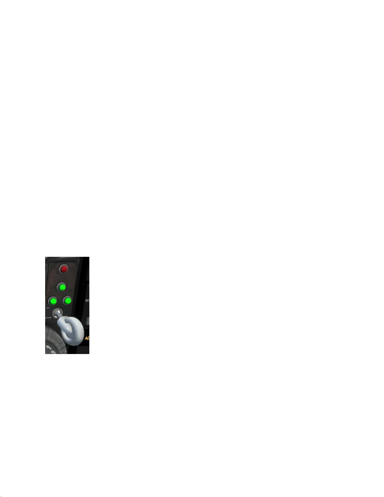
Step six: When you get airborne, you need to retract the gear. Locate the
gear handle (figure 8), which is located in a marvelously convenient and easy
to see location in the real airplane (putting tongue back in cheek now!). This
is why we allow you to hide the yoke bar! That gear lever is located on the
left half of the center console just below the mixture levers.
You can either cycle the gear using a physical controller button (the easy
way) or use your mouse to hover over top of the virtual knob in the VC,
left click and hold, then slide the mouse to toggle the handle up or down
way). Either way, the gear will retract. When the three green lights are
all illuminated, then it means all three landing gear are down and locked
and you can safely land on the gear. When the red light is illuminated, it
means the gear are “in transit,” meaning they are either moving up to retract or moving
down to extend. When all the lights are off it means the landing gear are fully retracted.
Step seven: Now you are flying, and frankly at this point if you want to understand all the
myriad of factors involved in properly flying a piston twin aircraft, you have no choice but to
read the POH. Because if we tried to explain it all here, then we’d duplicate the POH in about
all its slightly over 100 page glory! So, once again, please allocate the time to read the POH.
Figure 8

At the minimum, you will need to trim the elevators very frequently as speed and power
settings are changed. The easiest way to trim is to assign the function to a physical controller
button, ideally a rocker type button. When we say “trim constantly,” we mean just that!
Airplanes like this don’t fly automatically. They require constant loving attention from the pilot
and trim is essential to make the it friendly. The best description is that you force the yoke in
the position required to achieve the flight condition you desire, and then you trim out the
control forces your muscles are exerting. This is where pilots learn to become pilots and once
you learn, you learn to love doing it!
To climb, you set what is called “25 squared.” This means you set 25 inches of manifold
pressure (or full throttle when the air gets too thin above 5,000 feet MSL to no longer allow 25
inches of MP), and 2500 RPM’s. Additionally, you have to lean the engine’s fuel flows as you
climb into the thinner air. To do this, you use the two mixture controls on the right side of the
throttle quadrant. You have a fuel flow gauge to the immediate right of the Manifold Gauge to
help this leaning function. Where the bottom of the green arc is located, you see something
labeled 75% power. Lean back until the two needles (for left and right engines) mark this
position.
At this point, you have leaned out to optimal fuel/air ratio and are producing the maximum
amount of power you can at your current manifold and RPM settings (figure 9). Properly
controlling aircraft power in the myriad of flight conditions associated with climb, cruise, and
descent is complicated and once again can only be fully understood with a complete reading of
the POH!
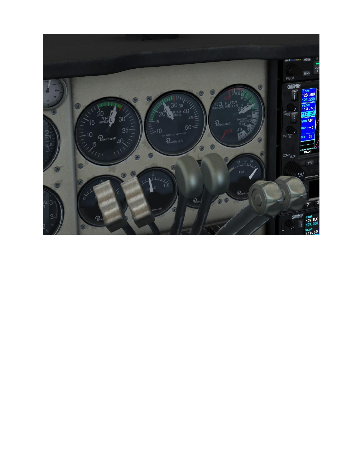
Figure 9
Note that in figure 9 how the six levers on the throttle quadrant are arrayed, and how the
needles on the three primary engine gauges appear. This is the quintessential “25 squared”
setting as you can see how the RPM, manifold, and fuel flow values are symmetrical for the left
and right engines (overlapping needles) and are set at 2500 RPM’s, 25 inches of MP, and that
75% power fuel flow status. Note, this screen capture was taken just as the aircraft was passing
5,000 feet MSL and that is why the throttles in the center are full forward. Climb above 5,000
feet MSL will see the MP decline the higher you go from there even with the throttles full
forward.
Step eight: There is an old as aviation adage, “Takeoffs are optional – landings are mandatory!”
Now it is time to think about landing. Piston twins are designed for raw climb power and
speed. So, to land them we have to fly them slower than their ideal cruising speeds. To do this,
we need to know the proper power and aircraft attitude management techniques, which is a
fancy way of saying to configure the flaps and gear, plus use the engine controls (throttles, prop
controls, and mixtures) to set the ideal manifold pressures and RPM’s on the left and right
engines.
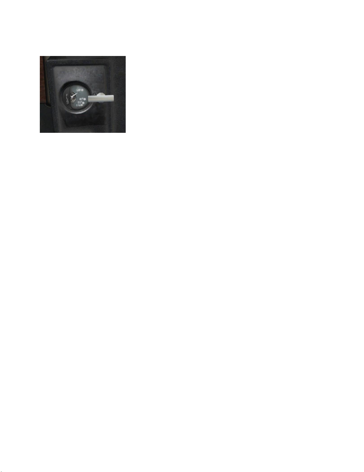
One of the prime pieces of gear used to perform slower flight required to approach and land
are the flaps. To control the flaps on this Baron 55, you have a
flap handle located on the left side of the center throttle console
(figure 10).
In the real airplane, you have to press and hold the flap handle
down or up to extend or retract the flaps, and then you release
when the indicator immediately left shows the desired flap
setting. In this virtual Baron 55, you should assign the flaps
operation to a two-way button on your physical controller. In
Figure 10 addition, vice flaps anywhere you practically want them, you have
two positions pre-set and selected in sequence.
You can also perform this operation by hovering the mouse pointer over the handle, press and
hold the left mouse button, and slide the mouse to slew the handle down or up as desired.
Flaps are just a small part of the total. Ultimately, a good approach and landing is management
of power to attain and maintain desired speeds and pitch on approach, final approach, crossing
the runway, and ultimately touchdown. You then use constant elevator trim to remove any
control input forces on the yoke required to maintain the desired pitch. To measure all this,
use those same instruments shown in figure 9 and also reference your airspeed gauge. So, how
do we do this, in the nutshell?
1. When you get about ten miles from your destination airport, throttle down to about 19
inches of manifold pressure and wait for the airspeed to bleed down in level flight to at or
below 160 KIAS. Then, lower the flaps its first notch ONLY. (Note: if you drop the flaps to the
full down position of 30 degrees when faster than 122 KIAS, then you can damage the flaps.)
The speed should bleed down further to below 153 KIAS where you can lower the landing gear
without damaging it. Again, position the yoke to achieve the pitch angle required to maintain
level flight with this configuration and then trim the elevators to remove the yoke control
forces needed.
2. You should already be familiar with what is called an airport traffic pattern. If you are
not, then view the FSX tutorial pilot training videos. Once you understand the pattern, then
when you are on the downwind leg and abeam your intended touchdown spot on the runway,
lower your landing gear and set 17 inches of manifold pressure, push the prop control levers
full forward to their maximum RPM settings, and then set the mixtures to either their full
forward (full rich) position, or to the setting required for a high altitude airport (an airport
above 5,000 feet MSL). Trim the aircraft elevators to support a descent rate of about 500 feet
per minute and at a constant airspeed of 100 KIAS (referred to as Vyse or “blue line speed”

because of that long blue radial line on the airspeed gauge). If you want to know what the deal
is with Vyse and why it is so vital to safe operation of a piston twin, then again, read the POH!
3. When your intended runway touchdown spot gets behind your shoulder on about a 45
degree angle, then turn to your base leg. When the runway is at your ten o’clock position (no
wind), then turn to final approach. When you are about one to two miles from the approach
zone of the runway and the runway is clear and then commit to landing. Extend your flaps to
full down, and use your rudders to make very fine adjustments as necessary to remain on
runway centerline. As you approach the runway leading edge, smoothly throttle back to idle
and keep the nose pointed at your runway aim point (which should be about 300 feet prior to
your intended touchdown point).
4. When you are about a half a wing length above the runway (hopefully on centerline)
rotate the nose to level and watch the airspeed bleed down. (In real aviation, this become
more a feel of listening to the airstream plus gauging the speed of the ground rushing by as you
keep your eyes glued to the far edge of the runway to maintain orientation). As the speed
bleeds down close to stall speed, pull the yoke a bit more aft so you touchdown on the main
landing gear (this is called the flare).
In summary, good landings are essentially all about pitch, power and speed control. When you
need to increase descent rate, you reduce power and pitch the nose down. When you need to
decrease descent rate, you add power and pitch the nose up. You adjust the power and the
pitch the nose at the same time –this is called “pitch and power.” Pitch and power on
approach to land are like conjoined twins –they go together and stay together!
To accurately touchdown on the optimal spot on the runway, you use a three-step process,
called “Aim, Level, Flare.” On final approach, you aim the aircraft’s nose at a spot about 300
feet prior to your desired touchdown spot on the runway. As written above, when you get
about a half a wing’s length above the runway, you pull back the yoke and rotate the nose to
level pitch. As your airspeed approaches stall speed (bottom of the white arc on your airspeed
gauge with gear and flaps down) you pull the yoke back further to the nose high flare position,
which should be about five to ten degrees nose high. Ideally, this is done in one continuously
smooth and fluid yoke motion.
At this point, you should touchdown. If you have crosswinds, then you have to use rudder to
point the nose down centerline and use the ailerons to “bank into the wind” to cancel out any
sideways drift caused by the crosswind. This is called “cross-controlling” the aircraft. This is
easy to explain, but pulling it off accurately is rightly called the “artwork of piloting.” To perfect
this we have three words: Practice, Practice, and Practice!

One final point, nothing in aviation is perfect. While the principles of aviation are very much
scientific, the reality of piloting an airplane is very much practiced artwork based upon sound
understandings of the scientific principles involved! Once you study the POH, you will
reference the power settings and speeds required for a good approach to landing. But, you
must remember that every day is different in temperature and atmospheric conditions. A given
manifold pressure setting will achieve the ideal speed on one day, but on another day will need
tweaking to achieve the optimal speed. This becomes the variations in aviation that pilots also
come to love –the constant challenge of taking a machine into the air and plying your craft
with precision and skill.
Congrats! You have flown the Baron 55! Now, once the initial joy subsides, follow that most
timeless of all instructor admonitions to student pilots, “Get in the books!”
Cheers,
Ken Stallings
Military Visualization Staff
Contract US Air Force Instructor Pilot
FAA Commercial AMEL/ASEL Pilot
Beechcraft® Baron® B55 is a trademark of Textron Aviation Inc. and is used under license to
RailSimulator.com Ltd d/b/a Dovetail Games.
Other Beechcraft Aircraft manuals

Beechcraft
Beechcraft Duke 60 Series User manual

Beechcraft
Beechcraft Bonanza 36 Owner's manual

Beechcraft
Beechcraft C-12C Use and care manual

Beechcraft
Beechcraft Baron G58 Owner's manual

Beechcraft
Beechcraft Debonair 35-33 Owner's manual

Beechcraft
Beechcraft C23 SUNDOWNER 180 Owner's manual

Beechcraft
Beechcraft Bonanza V35B-TC User manual

Beechcraft
Beechcraft Debonair C33 User manual

Beechcraft
Beechcraft Baron 58 Owner's manual

Beechcraft
Beechcraft TRAVEL AIR 95 Install guide


