manuals.online logo
Brands
  1. Home
  2. •
  3. Brands
  4. •
  5. Bego
  6. •
  7. Food Warmer
  8. •
  9. Bego Gelovit 200 User manual

Bego Gelovit 200 User manual

F&E Equipment
Service manual V1.0 Gelovit 200
Autor : Fin/DW Stand 11.02.09 Seite 1 von 6
Gelovit 200 – Software V1.00
F&E Equipment
Service manual V1.0 Gelovit 200
Autor : Fin/DW Stand 11.02.09 Seite 2 von 6
This handbook describes functions, which are not described in the manual of the device. It
is only valid for Gelovit 200 with brushless drive.
1. Commissioning
The device shows first the software version in the display and then the unit of the tempera-
ture in °C or °F.
2. General notes
The motor starts running at a specified temperature of 50°C/122°F and is accelerated and
braked by ramps. The speed of the motor and the fan is controlled by the software. The
heating circuits are proportionally controlled to the required performance.
F&E Equipment
Service manual V1.0 Gelovit 200
Autor : Fin/DW Stand 11.02.09 Seite 3 von 6
3. Connections and LEDs
LED cover LED heater (bottom) LED heater (top) connections of the motor
Wiring of the Motor (from left to right): Red - black - green - yellow - white - Gray
4. Settings
4.1 Shifting °C / °F
Press and hold the timer button and the cycle button and switch on the device. When the
device has beeped 4 times, release the buttons. The new setting will be displayed.
F&E Equipment
Service manual V1.0 Gelovit 200
Autor : Fin/DW Stand 11.02.09 Seite 4 von 6
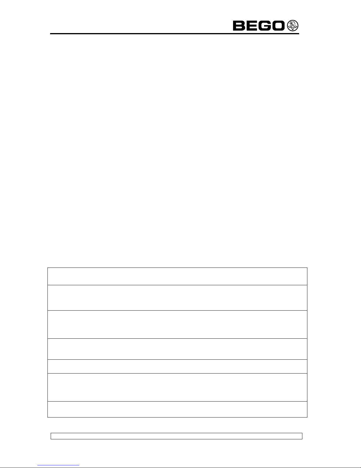
4.2 Resetting hours of operation (device)
Press and hold the cycle button and switch on the device. When the device has beeped 4
times, release the buttons.
4.3 Resetting hours of operation (motor)
Press and hold the timer button and switch on the device. When the device has beeped 4
times, release the buttons.
4.4 Fan test
Press and hold the T1 button and switch on the device When the device has beeped 4
times, release the buttons. By pressing the T1 button, different levels in percent are
switched and shown in the display.
Attention: The fan speed is not proportional to the percentage on the display. Voltage fluc-
tuations of the power supply are automatically adjusted.The device remains in the fan test
mode, please switch it off/on the device to turn back to the user mode.
4.5 Motor test
Press and hold the T2 button and switch on the device. When the device has beeped 4
times, release the buttons. By pressing the T2 button, different levels in percent are
switched and shown in the display.
The speed of the motor is proportional to the percentage display. T2 LED flashes in the
rhythm of the rotation sensor. Switch off/on the unit to return to the user mode.
4.6 Test of heaters and sensors
Press and hold the T3 button and switch on the device. When the device has beeped 4
times, release the buttons. Heaters can be switched as follows:
T1 button: heater (top) on/off = LED T1 on/off
T2 button: heater (bottom) on/off = LED T2 on/off
The display shows the pot temperatures top and bottom in °C without decimal places (eg
47:68). When the temperature of 99°C was reached, t he heaters are automatically switched
off (safety shut down). Switch off/on the unit to return to the user mode.
F&E Equipment
Service manual V1.0 Gelovit 200
Autor : Fin/DW Stand 11.02.09 Seite 5 von 6
4.7 Readout of the hours of operation (device)
Switch on the device and wait until the device is ready to work. Press and hold the cycle
button. When the device has beeped 4 times, release the button. The device shows you
the operating hours now. The displayed value must be multiplied with 10.
4.8 Readout of the hours of operation (motor)
Switch on the device and wait until the device is ready.
Press and hold the timer button. When the device has beeped 4 times release the button.
Device shows the operating hours of the motor now. The displayed value must be multiplied
with 10.
4.9 Calibrating the sensors
Switch on the device and wait until the device is ready. Press and hold the T1&T2&T3 but-
tons. When the device has beeped 4 times, release the buttons.
With + / - buttons it is possible to set a correction value of ±0.9 °C for the sensors. Upon
delivery, this value is 0. The device remains in the calibrating mode, please switch it off/on
the device to turn back to the user mode.
5. Known bugs
Currently no
6. Elimination of faults
Fault Cause Remedy
SOS sound display or cable to the display Call Customer
defective Service Dept.
E01 Gel sensor defective Sensor exchange,
E02 Lower temperature sensor defective PCB exchange
E03 Upper temperature sensor defective
E04 Rotary sensor defective Motor exchange,
PCB exchange
E05 Clock defective PCB exchange
E20 24V supply failure Check fuses,
Check power
supply at PCB
E30,31,32 engine brake failure PCB exchange
F&E Equipment
Service manual V1.0 Gelovit 200
Autor : Fin/DW Stand 11.02.09 Seite 6 von 6
Additional information
E01 – E03 are created, when the sensor signal is< 1°C or > 120°C. The errors switch off
the motor and the heaters (safety). The device cannot be used any longer.
E04 is generated by the internal rotation sensor of the motor. This error is appearing alter-
nately with the gel temperature in the display (Emergency operation).
E05 is generated when the timer for the required clock doesn’t run. This bug switches off
the motor and heaters, the device cannot be used any longer. Power failures during timer
operation are intercepted by a maintenance-free storage capacitor.
E20 is generated when the 24V power supply for the motor has failed. This bug switches off
the motor and heaters, the device cannot be used any longer.
E3x is generated when the cover is opened while the motor is running. The cover switch
controls a relay and a brake of the motor. If the motor doesn’t stop immediately , the brak-
ing function hasfailed. The emergency operation is possible, but strongly discouraged.
Keep the cover closed!
Note: the previously used error E8 (cover open) was replaced by the word ‘OPEN’ in the
display.

Other manuals for Gelovit 200

3

Popular Food Warmer manuals by other brands

Taiji HS-03 operating instructions

Taiji

Taiji HS-03 operating instructions

Kontour K1023E installation guide

Kontour

Kontour K1023E installation guide

APW Wyott W-3V Specifications

APW Wyott

APW Wyott W-3V Specifications

Lakeland 23358 user manual

Lakeland

Lakeland 23358 user manual

Wells HT-227AF Specifications

Wells

Wells HT-227AF Specifications

Pro-Idee 653-444 manual

Pro-Idee

Pro-Idee 653-444 manual

Tuzio Savoy E1011 installation guide

Tuzio

Tuzio Savoy E1011 installation guide

Maxima MPW2 40 Series user manual

Maxima

Maxima MPW2 40 Series user manual

Omcan FW-TW-5000-R instruction manual

Omcan

Omcan FW-TW-5000-R instruction manual

Adler Europe AD7439 user manual

Adler Europe

Adler Europe AD7439 user manual

Celestron Gamekeeper ThermoCharge 93550 quick start guide

Celestron

Celestron Gamekeeper ThermoCharge 93550 quick start guide

Delfield Shelleyglas KH-2 Specifications

Delfield

Delfield Shelleyglas KH-2 Specifications

Randell 3500 Specifications

Randell

Randell 3500 Specifications

True Manufacturing Company TH installation manual

True Manufacturing Company

True Manufacturing Company TH installation manual

Bella 13337 instruction manual

Bella

Bella 13337 instruction manual

VIZU VI016 manual

VIZU

VIZU VI016 manual

Hatco Glo-Ray GR2SD Series Installation and operating manual

Hatco

Hatco Glo-Ray GR2SD Series Installation and operating manual

True TG1H-1S Specifications

True

True TG1H-1S Specifications

manuals.online logo
manuals.online logoBrands
  • About & Mission
  • Contact us
  • Privacy Policy
  • Terms and Conditions

Copyright 2025 Manuals.Online. All Rights Reserved.