BEHLMAN PF1350 Series Use and care manual

PF1350 TECHNICAL MANUAL REV 1 2/06/14
USER'S GUIDE AND
TECHNICAL REFERENCE
BEHLMAN MODEL
PF1350 SERIES AC POWER SUPPLY
PART NO. 108-017-004
FOR SERVICE ASSISTANCE
CONTACT BEHLMAN
CUSTOMER SERVICE DEPARTMENT
PHONE TOLL FREE 1-800-874-6727
OR WRITE
BEHLMAN
CUSTOMER ELECTRONICS DEPARTMENT
80 CABOT COURT
HAUPPAUGE, NY 11788
PHONE: (631) 435-0410
FAX : (631) 951-4341
FOR SALES INFORMATION:
PHONE: (631) 435-0410
USA : (800) 874-6727
FAX : (631) 951-4341

PF1350 TECHNICAL MANUAL REV 1 2/06/14
LIMITED WARRANTY
Behlman Electronics, Inc. warrants, to the original purchaser, for a period of one (1) year from the
date of shipment from Behlman, each item to be free from defects in material and workmanship.
Bellman’s obligation and the Purchaser's sole remedy for any breach or violation of this agreement is
limited to adjustments, repair or replacement for parts which have been promptly reported by the
Purchaser as having been, in its opinion, defective and so found by Behlman upon inspection. All
replacement parts will become the property of Behlman on an exchange basis. This warranty will not
apply if such adjustments, repair or parts replacement is required because of accident, neglect,
misuse, failure of environmental controls, transportation damage or causes other than normal use.
If during the warranty period a defect should impair the performance of the unit, Behlman agrees, at
its option, to repair or replace the unit or its defective components F.O.B. Behlman at 80 Cabot
Court, Hauppauge New York 11788 or at another Behlman service facility at Bellman’s option. To
obtain service under this warranty, the original Purchaser shall notify Behlman at the above address
or by Telephone at 631-435-0410 and provide information about the defect or impairment of
performance. Behlman will then supply the Purchaser a Return Material Authorization (RMA)
number. This number must be attached to the equipment sent back for warranty repair. Equipment
must be shipped back to Behlman prepaid. No collect shipments will be accepted.
Behlman shall be excused from supplying warranty service if the equipment covers have been
removed or if the unit has been subject to unauthorized repair. All service outside the scope of this
Warranty shall be paid for by the Purchaser at Bellman’s rates in effect at the time of repair. Behlman
will not perform any repairs outside of the Warranty without written authorization by the Purchaser.
If the repair is a warranty repair, Behlman will ship the unit back to the Purchaser, by a method
determined solely by Behlman, prepaid. If the Purchaser requests any other means of transportation
it shall be at the Purchaser's expense.
The use of the equipment shall be under the Purchaser's exclusive management and control. The
Purchaser will be responsible for assuring the proper installation, use, management and supervision
of the equipment. Behlman will not be liable for personal injury or property damage.
The foregoing warranties are in lieu of all other warranties, expressed or implied including without
limitation warranties of merchantability and fitness for purpose.
In no event shall Behlman be liable for loss of profits, loss of use, or any other indirect, consequential
or incidental damages. Purchaser agrees that Behlman will not be liable for any damages caused
by the Purchaser's failure to fulfill any of the Purchaser's responsibilities set forth herein.

PF1350 TECHNICAL MANUAL REV 1 2/06/14
CLAIM FOR DAMAGE IN SHIPMENT
Under the FOB factory terms of sale, ownership and responsibility are transferred to the customer when the
equipment leaves the factory. Each Behlman instrument is shipped from the factory in proper operating condition.
Immediately upon receiving equipment, unpack and inspect it for evidence of damage incurred in shipment. I F
equipment is damaged, file a claim with the freight carrier. Forward a copy of the damage claim report to
Behlman. Include the model number, serial number and date the shipment was received. Behlman will advise
the disposition of the equipment and will arrange for necessary repair or replacement.
RETURNING EQUIPMENT TO FACTORY
Do not return equipment to the factory without prior authorization from Behlman.
This equipment, like all precision electronic equipment, is susceptible to shipping damage. It contains heavy
magnetic components as well as delicate electronics components. If equipment is returned without prior
authorization, the shipment will be refused and the customer will be liable for all shipping, handling and repair
costs. When packing for reshipment, use the original shock absorbent material and shipping container to prevent
additional damage to the equipment.
Ensure that the return authorization numbers (RMA) is available on the container.
PACKING INSTRUCTIONS
RACK MOUNTED UNITS
I) Box(es) must be double wall with minimum 350 lbs. bursting test.
2) Box(es) must provide for a minimum of 2 to 3 inches of clearance around sides, top and bottom of
unit.
3) When packing unit, utilize either a foam-in-place system or high density foam. Clearance provided
for above must be completely filled with foam.
FAILURE TO COMPLETELY SECURE UNIT IN BOX WILL ALLOW MOVEMENT
DURING SHIPPING, RESULTING IN DAMAGE.
DO NOT USE PEANUTS OR BUBBLE
WRAP
4) Secure box(es) to pallet(s). This is necessary to insure proper handling and protection during
shipping.
5) Place the following warning label on box(es)
DO NOT STACK
6) Ship unit using a freight cargo carrier; air or ground.

PF1350 TECHNICAL MANUAL REV 1 2/06/14
SAFETY SUMMARY
The following safety precautions must be observed during all phases of operation,
service, and maintenance of this equipment. Failure to comply with these precautions
or with specific warnings elsewhere in the manual violates safety standards associated
with the design and intended use of this equipment. This manual forms an integral part
of the equipment and must be available to operating personnel.
GROUND THE EQUIPMENT
This equipment may have high leakage current to chassis due to EMI filtering requirements.
To minimize shock hazard, the equipment chassis(s) must be connected to an electrical safety
ground. This equipment is supplied with a three conductor line connection for single phase
applications and/or a five wire connection for three phase applications. Both types include an
earth terminal intended for safety ground connections. In addition, isolated installation sites
may require neutral to earth connections as per NEC section 250 (National Electrical Code).
Refer installation to licensed electrician or other qualified personnel.
DO NOT OPERATE IN EXPLOSIVE ATMOSPHERE
Do not operate the equipment in the presence of flammable gases or fumes. Operation of any
electrical instrument in such an environment constitutes a definite safety hazard.
KEEP AWAY FROM LIVE CIRCUITS
Operating personnel must not remove equipment covers. Component replacement and internal
adjustments must be made by qualified maintenance personnel. Do not replace components
with power applied. Under certain conditions, dangerous voltage may exist even with the
power removed. To avoid injuries, always disconnect power and discharge circuits before
touching them. During normal operation the operator does not have access to internal
hazardous voltages. However, depending on the user’s application configuration, HIGH
VOLTAGES HAZARDOUS TO HUMAN SAFETY are normally generated at the output
terminals. The customer/user must insure that the output power lines are labeled properly as
to the safety hazard and that any inadvertent contact is eliminated.
DO NOT SERVICE OR ADJUST ALONE
Do not attempt internal service or adjustment unless another person, capable of rendering first
aid and resuscitation is present.
DO NOT SUBSTITUTE PARTS OR MODIFY INSTRUMENT.
Because of the danger of introducing additional hazards, do not install substitute parts or
perform any unauthorized modification to this equipment. Contact Behlman Electronics for
proper replacement parts and specific service information.

PF1350 TECHNICAL MANUAL REV 1 2/06/14
DANGEROUS PROCEDURE WARNINGS !
Warnings will precede potentially dangerous procedures in this manual. Instructions contained
in the warning must be followed. Warnings will be preceded by the caution symbol (above).
RISK OF ELECTRIC SHOCK
This symbol warns personnel of hazardous conditions due to the exposure of hazardous
voltage that can be harmful if contacted.
Neither Behlman Electronics , Hauppauge , NY, USA, nor any of the subsidiary sales
organizations can accept any responsibility for personnel, material or inconsequential injury,
loss or damage that may result from improper use of the equipment and/or accessories
provided.
For additional safety related technical information , contact the Behlman Electronics sales
department or local sales representative.
or call in N.Y.
631-435-0410

PF1350 TECHNICAL MANUAL REV 1 2/06/14
TECHNICAL MANUAL PF1350 AC POWER SUPPLY
TABLE OF CONTENTS
Section Title
1.0 Introduction
1.1 Specifications
1.2 Unpacking & Inspection
2.0 Installation
2.1 Power Requirements
2.2 Wiring
3.0 Operation
3.1 Features and Indicators
3.2 Operational Considerations
4.0 Maintenance/ Trouble Shooting
4.1 Performance Verification
5.0 Mechanical Outline
PF1350 TECHNICAL MANUAL REV 1 2/06/14
SECTION ONE
INTRODUCTION
1.0 The Behlman PF series of AC power supplies are designed to provide regulated AC
power at frequencies and /or voltages not available from local utilities. All models are
completely solid state, PWM switching types that provide high efficiency and overall
reliability. These devices require very little maintenance and will provide years of trouble
free service when used within their ratings. The models in this series include an active
power factor correction circuit to reduce input harmonics associated with the conversion
process used. These models are housed in an all steel, EIA rack mountable enclosure.
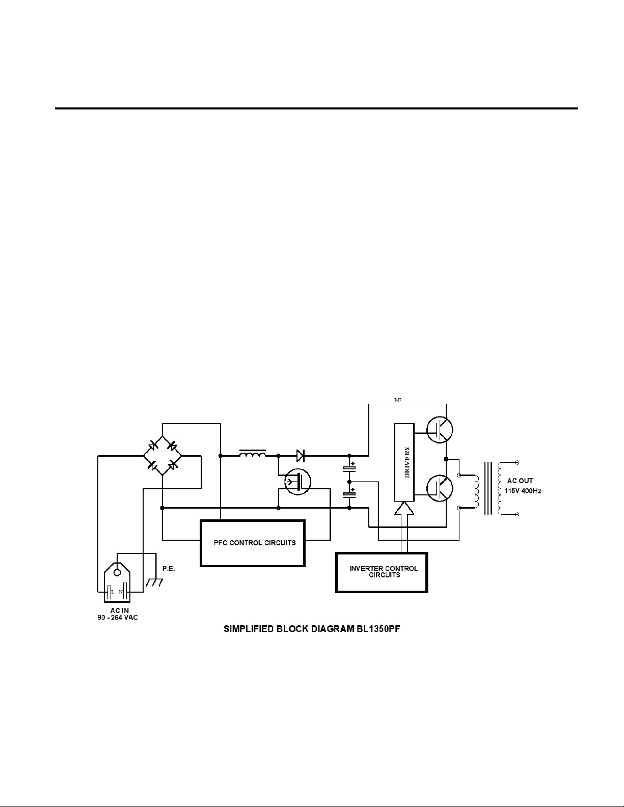
The block diagram below illustrates the conversion process performed by this
equipment. AC power is applied and converted to DC by an active power factor
corrected boost converter. This DC is then used to provide raw power for a class D
amplifier. The amplifier is driven from a reference signal at the desired output frequency.
The resulting amplified signal is applied to a step-up transformer to provide both
isolation and the desired output voltage. Short circuit protection and current limit are
performed by the control electronics.

PF1350 TECHNICAL MANUAL REV 1 2/06/14
SECTION ONE
1.2 SPECIFICATIONS FOR AC POWER SUPPLY PF 1350 SERIES
INPUT POWER REQUIREMENTS: 95* to 270 VAC** 47 - 63 Hz @ 18A Max.
(Full power from 108V – 267V)
(*) input current limited to 16A.
AC OUTPUT POWER: 1200W (with 120 - 270VAC Input)
OUTPUT FREQUENCY: 50, 60, or 400Hz, +/- 0.1%, switch selectable
AC OUTPUT T.H.D. 1.5% TYPICAL @ 120V / 50Hz, resistive.
AC OUTPUT CURRENT: 10A @ 135V RANGE, 5A @ 270V RANGE.
AC REGULATION: 1 % No load to Full load, resistive.
AC REGULATION RESPONSE TIME 250 – 300 mSec, typical.
METERING:
VOLTAGE: +/- (1% of reading + 1% of range), 1V res.
PHYSICAL: 19” W x 17” D x 3.5” H EIA standard for 19”
Rack mount cabinets ( with RM kit ).
WEIGHT: 39 lbs. ( 17.6 kgs)
OPERATING TEMPERATURE: 0 to +40 degrees Celsius.
STORAGE TEMPERATURE: -10 to +60 Degrees Celsius.
SAFETY: Evaluated to IEC-61010, general safety ,
Class1, pollution level 2. ** To conform, input
voltage is limited to 250VAC.

PF1350 TECHNICAL MANUAL REV 1 2/06/14
SECTION ONE
1.3 UNPACKING AND INSPECTION
Remove the equipment from its packaging and inspect it for shipping damage. If the box
shows signs of damage, retain it in case a claim needs to be filed with the shipping
carrier. If the equipment shows signs of damage, DO NOT attempt to operate it. Contact
Behlman immediately and file a damage claim with the shipper. Prior authorization is
required before sending any equipment back to Behlman. This is in the form of a
Returned Material Authorization number that must be obtained from Behlman. Any
shipment sent without an RMA # will be refused and the customer will be liable for all
shipping costs.
This equipment does not ship with any other accessories. A copy of the user/technical
manual is provided in the shipping container. It is recommended that the serial number
be verified and retained in case of any warranty claims. The warranty for this unit is one
year for parts and labor. See the Warranty statement at the beginning of this document
for specific information. All warranty repairs must be performed by Behlman or one of its
warranty repair or Reps.
PF1350 TECHNICAL MANUAL REV 1 2/06/14
SECTION TWO
INSTALLATION AND WIRING
2.1 INSTALLATION
This device is designed primarily for desktop or bench top operation. This model may
also be mounted in an EIA standard equipment rack using the RM adaptor kit available
from Behlman. If the unit is to be rack mounted, it must be placed so as not to block the
cooling vents on the sides, top, and rear panels. Rear support must also be provided.
This may be in the form of internal support “rails” or chassis slides. Many equipment
rack manufacturers can supply generic support brackets or shelves to be used with their
racks. Racks that are completely sealed will require ventilation to remove heat
generated by the AC power supplies exhaust.
The installation site must protect the power supply from moisture and any conductive
particulate matter. IN NO CASE should this unit be operated in the presence of dripping
or misting fluids. For continuous full power output, the ambient operating temperature
should not exceed 40 degrees Celsius.
WARNING !
INSTALLATION AND OPERATION
MAY EXPOSE PERSONNEL TO HARZARDOUS
VOLTAGE AND CURRENT LEVELS
2.2 INPUT POWER CONNECTION
This unit operates from any AC voltage from 95 -270V with a frequency between 47 and
63 Hertz. A detachable line cord is provided that mates with the IEC-19 type receptacle
(JI) on the rear panel. The other end of the supplied line cord is left un-terminated so
that the end user can affix the proper plug to mate with power receptacles available at
the installation site. Conformance to IEC safety standards limits the input to 250VAC.
WARNING
THIS DEVICE IS SUPPLIED WITH A 3 WIRE LINE CONNECTION THAT INCLUDES A PROTECTIVE
EARTH CONDUCTOR (YEL/GREEN WIRE). THIS CONNECTION IS CRITCAL TO OPERATOR
SAFETY AND MUST BE TIED TO THE INSTALLATION SITE PROTECTIVE EARTH. DUE TO
COMPONENTS USED FOR EMI REDUCTION, THIS DEVICE MAY PRODUCE LEAKEAGE
CURRENTS THAT ARE HAZARDOUS. THE EARTH CONNECTION PROVIDES A RETURN PATH
FOR THESE CURRENTS.

PF1350 TECHNICAL MANUAL REV 1 2/06/14
2.3 AC OUTPUT LOAD CONNECTIONS
Connect the load to the front panel AC output SCHUKO socket. A universal adapter is
(P/N 107-771-007) provided to suite most needs. Other output adaptors are available
and the end user should contact the Behlman sales department for specific needs. Units
ordered with the TB option are provided with an additional set of compression type
terminals on the rear panel. These terminals are wired in parallel with the front panel
SCHUKO socket. Note that this device produces output voltages that are hazardous
under normal conditions. The end user must make sure that all output wiring is installed
in a way that prevents inadvertent contact with operating personnel. The use of
warning labels is highly recommended.
The output circuit of this device is transformer coupled and floating with respect to the
input line. Either side of the AC output may be tied to protective earth or other potential.
The maximum continuous floating voltage between either output terminal and ground is
500VDC. Refer to figure 2-1 for an illustration of typical output circuit configurations.
Figure 2-1

PF1350 TECHNICAL MANUAL REV 1 2/06/14
SECTION THREE
OPERATION
3.1 CONTROLS AND INDICATORS
Table 3-1 below lists the controls, indicators, and other features associated with the
model PF1350 AC power supply. Refer to figure 3-1 for locations.
Table 3 -1
ITEM DESIGNATION COMMENT/DESCRIPTION
1 AC Line switch Power on/off switch.
2 LED fault indicator Illuminates during output faults caused by
either over temperature or output short circuits
(see text).
3 Digital Voltage Display 3 digit readout to display output volts.
4 FREQUENCY Select Switch 3 position, rotary switch selects output
frequency of power supply. These are 50Hz,
60Hz or 400Hz.
5 VOLTS adjust Multi-turn control that provides continuous
output voltage adjustment. Available with
optional locking device.
6 RANGE switch Rocker type switch used to set output voltage
range of either 0 – 135Vrms or 0 -270Vrms.
7 Front Panel Output socket SCHUKO type “socket” provides direct
connection to loads. This socket will also
accept various adaptors. A universal type
adaptor is provided with the power supply.
8 Rear Panel Output (TB option only) Optional rear panel mounted, compression
type terminals that accept up to 10 AWG wire.
In parallel with front panel output.
9 J1 AC Line input IEC-20 receptacle.
10 F1 line Fuse 6.3 x 32 mm 16A /300V fuse. WARNING!
replace with same type and rating only.
11 Fan exhaust Heated air exists via these openings.
12 Remote interface ( optional) Optional isolated, analog remote control. See
manual text for additional information.

PF1350 TECHNICAL MANUAL REV 1 2/06/14
FIGURE 3.1
142 3 5 6 7
89
10
11
12
FRONT PANEL
REAR PANEL
PF 1350 CONTROLS AND INDICATORS

PF1350 TECHNICAL MANUAL REV 1 2/06/14
3.2 OPERATING INSTRUCTIONS
1. Connect the unit to a source of AC power between 90 & 267 Vrms and 47-63Hz.
NOTE: for full power operation, input must be at least 105V. Conformance with
IEC safety standards limits the input to 250Vac. See section 2 of this manual for
specific wiring information.
2. Set the PF1350 front panel controls as follows:
RANGE = As desired for load (Note: button in is high range)
FREQ = To desired value of 50, 60, or 400Hz
VOLTS = Fully Counter Clockwise (CCW)
With loads connected and switched off (recommended), turn on the front panel switch
and allow a few seconds for the power supply to stabilize. Use the VOLTS adjust
controls to set the desired output voltage as indicated on the display.
3. To shut down, turn of front panel power switch.
NOTE: once the unit is switched off, a period of 10 seconds must be allowed before
the unit is switched back on. Failure to do so may cause tripping of upstream circuit
breakers.
It is also possible to have the output voltage set at zero, and then to turn on the load
switch. The voltage can then be increased to the required operating point by adjusting
the VOLTS control clockwise. This method works best with linear loads and may be
desirable for certain applications.
3.3 OPERATING CONSIDERATIONS
The output voltage and frequency may be varied at any time while the unit is loaded.
It is recommended that the load be disconnected (off) while changing the range setting.
This will prevent potentially damaging transients from reaching the load.
These AC power supply models are based on electronic circuits that utilize various
power semi-conductors. As such, there is a limit to the amount of current that can be
supplied.
Certain loads may draw short duration, very high peak currents that may activate
protection circuits within the AC power supply. The Model PF1350 incorporates two
distinctive over current circuits. The first responds to massive overloads like short
circuits. This circuit can respond in a few tens of microseconds. Once activated, the AC
output of the power supply is disabled and the front panel fault LED is illuminated. To
recover from this type of overload, the input power must be cycled off for about 30
seconds.

PF1350 TECHNICAL MANUAL REV 1 2/06/14
3.3 OPERATING CONSIDERATIONS (continued)
The second current limit circuit responds to long term overloads. Once the current is
increased beyond the output rating, the unit will enter a constant current mode. In this
mode, the output voltage will reduce to limit the current if the load resistance is reduced
further. The voltage will recover automatically once the overload is removed. The front
panel Constant Current LED may light or flash under these conditions depending on the
nature of the overload.
The internal temperature of the unit is monitored. If the temperature rises above a safe
value, the outputs will be disabled and the front panel fault LED will turn on. Normal
operation will resume once the unit has cooled to a safe level.
3.4 LIMITING LOAD IN RUSH CURRENTS
Loads that present high inrush currents may be started by limiting the current at start-
up. This can be done externally with a simple series resistor and relay. The resistor is
placed in series with the load for the estimated or measured inrush period. Once the
inrush current has stabilized or tapered off, the relay is used to switch the resistor out of
the circuit. NTC (Negative Temperature Coefficient) “thermistors” may be used. These
devices start off with a nominal resistance value when cold (off). Once power is applied
the current flow causes the temperature of the resistor to increase which in turn reduces
the value of the resistance. The “hot” value may be several times lower than the cold
value. These devices are available for currents exceeding 15 Amps.
3.5 OPERATION INTO LINEAR LOADS
The model P1350 will provide the best overall performance into a linear load. A linear
load is characterized by that fact that its current wave shape is sinusoidal. The phase
relationship between the voltage and current may be anything between zero and 90
degrees (leading or lagging). Some examples of linear loads are as follows: Most AC
Motors, Power Transformers, Heating Elements, Resistors, Capacitors, Most Inductors,
Incandescent Lighting ( without dimmers ), and most Solenoids
3.6 OPERATION INTO LINEAR LOADS
Operation into these types of loads usually causes little interaction with the AC power
supply. The main concern with a linear load is the inrush current associated with it. Most
heating elements and resistors have little or no inrush concerns and usually do not
present any problem for the power source. Inductive and capacitive loads may present
a special problem based on their construction and the way in which they are energized.
Motors and tungsten filament lamps also present some special Astart-up@concerns. The
following is intended to give the end user some insight into applying the AC source to
these types of loads.

PF1350 TECHNICAL MANUAL REV 1 2/06/14
OPERATING CONSIDERATIONS (continued)
3.7 DRIVING REACTIVE LOADS
Capacitors and inductors are reactive in nature. If the load is applied during the peak of
the AC cycle there may be a considerable inrush of current several magnitudes larger
than the steady state current. This current is only limited by any series resistance that
may be present in the load circuit. Under the right conditions, this could trip the overload
protection circuits in the power source. Certain transformers and solenoids (inductance)
present the same problem.
Several methods can be used to prevent tripping the protection circuits in the power
source. One common method is to insert a limiting impedance in series with the load.
This could be a fixed resistor or NTC (negative temperature coefficient) thermistor. Also,
zero crossing switching can be employed. The most obvious way to prevent a high in
rush current is to apply the load with the voltage set to zero (or some low value) and
energize the load slowly by turning up the voltage.
3.8 DRIVING LAMPS
Tungsten filament lamps, when cold, present a very low resistance. Once they are
energized, their resistance quickly climbs to a steady state value. This characteristic
must be accounted for when driving tungsten filament lamps. The same methods for
driving reactive loads can be applied to tungsten.
3.9 DRIVING MOTORS
Driving an AC motor presents a special problem. Most motors require a starting current
that is several times higher than the running current. This current may last for a few
cycles to several seconds depending on the construction and mechanical load on the
motor. This current is sometimes referred to as the motor=s Alocked rotor@current. This
current is not to be confused with the inrush current that usually occurs over the course
of one or two cycles of the AC waveform. The model P1351's fold back current limiting
can be an advantage when starting motors. During the starting period, the motor will
attempt to draw excessive power from the power source. The fold-back circuit will
reduce the output voltage in order to maintain the maximum current for the range in use.
3.10 OPERATION WITH REMOTE CONTROL OPTIONS
The PF1350 is available with a remote analog control option. This option allows isolated
control of the output voltage via a 0-10VDC analog signal. The output range may also
be set to high via this control.

PF1350 TECHNICAL MANUAL REV 1 2/06/14
P1350 with ANALOG REMOTE CONTROL OPTION - 4065
3.10.1 INTRODUCTION
This option provides a means of controlling the model P1350 output voltage with a 0-10Vdc analog signal.
In addition, the power supply's output range may be set to the high range via a digital input. This interface
provides complete isolation from ground and the power stage of the power supply. An additional terminal
block is fitted to the rear of the power supply chassis.
3.10.2 SPECIFICATIONS
0 To 10VDC Control Input Impedance ............................ 10K ohms minimum
Maximum Input Voltage ................................................+/- 15 VDC
Control Input to Output Linearity ...................................... 1% typical
Control Response Time .....................................................250mS typical
Isolation Voltage ................................................................500 VDC ( 300 VAC 60Hz )
3.10.3 CONTROL TERMINAL ASSIGNMENT ( TB-1 )
POS.
PIN NAME FUNCTION
TB1-1
VOLTAGE CONTROL 0-10VDC input control output ac voltage.
TB1-2
COMMON signal return for dc control
TB1-3
RANGE + 8 - 15 VDC set range to 0-270V
TB1-4
RANGE - 8 - 15VDC signal return
APPLICATION INFORMATION
To use the remote control features the front panel VOLTS controls MUST BE set fully counter clockwise.
The RANGE switch must be set to the "LOW" position. Note that the remote input is additive and will
increase the setting of the front panel controls.
Cables used to connect the control circuit to the power source should be shielded to prevent noiseand
electromagnetic interference from entering the remote inputs. A shielded twisted pair is recommended.
Cable shields should be terminated at the control side of the circuit. The maximum length of these cables
is dependent on the control circuit=s drive capability. It should be noted that some IC output stages may
become unstable and oscillate when driving long cables with high capacitance. Low output impedance
buffers should be considered when long cable lengths are desired.
The stability and regulation of the P1350 output voltage will be directly affected by the quality of the user
supplied control signals. This must be considered during the design of the control circuitry.

PF1350 TECHNICAL MANUAL REV 1 2/06/14
SECTION 4
MAINTENANCE AND TROUBLE SHOOTING
4.1 MAINTENANCE
These power supplies are completely self contained solid state devices and do not
require any routine maintenance. When used within their ratings they will provide many
years of trouble free service. The only foreseen maintenance issue would be
maintaining the ventilation “grills”. Any accumulation of dust and debris should be
removed by brushing or vacuuming.
4.2 TROUBLESHOOTING
THESE UNITS DO NOT CONTAIN USER SERVICABLE PARTS
REFER ALL SERVICING TO QUALIFED PERSONELL ONLY. DO NOT REMOVE COVERS
AND DISCONNECT POWER BEFORE REMOVING FOR SERVICE.
Table 4-1 below should be consulted In the event a problem is encountered during the
operation of this power supply.
OBSERVERED SYMPTOM
PROBABLE CAUSE
CORRECTIVE ACTION
No outputs, meter indicates 000 VOLTS control CCW Adjust VOLTS control CW
Load does not operate, unit
indicates proper output
Load not connected between
HI and Lo AC output.
Check load is switched on. Check
load is connected properly, See
section 2 and 3.
AC output low or fluctuates,
constant current LED is on or
flashing.
Output overload. Reduce load.
AC output distorted. Hi harmonic content to load
current. Non-linear load
applied
Check load current waveform.
AC output drops to zero when load
is switched on. Overload LED is
on.
Output overloaded or shorted
by large in-rush current.
Check load requirement, see
information in section 3 on starting
difficult loads.
No outputs, no displays, input fuse
blows repeatedly.
Internal fault. Remove unit from use and refer to
qualified service personnel.
Contact factory for service.
WARNING ! REPLACE FUSE WITH SAME TYPE AND RATNG ONLY.
6.3x32mm cartridge type, 16A / 300 VAC min voltage rating.

PF1350 TECHNICAL MANUAL REV 1 2/06/14
4.3 PERFORMANCE VERIFICATION
The following procedure can be used to verify operation and calibration of the PF1350
AC power supply.
WARNING !
THE FOLLOWING PROCEDURE EXPOSES PERSONNEL TO HAZARDOUS
VOLTAGE AND CURRENT LEVELS. REFER TO QUALIFIED PERSONS ONLY
4.3.1 EQUIPMENT REQUIRED
Table 4-1 lists the test equipment required to for performance verification. Other
equipment may be substituted provided that it meets the minimum requirements set in
the table.
# DESCRIPTION SUGGESTED TYPE MINIMUM
SPECIFICATIONS
1 AC WATTMETER YOKAKAWA WT-230 AC volts, amps, & frequency
0.25% to 500Hz.
2 TEST LOAD BANKS AVTRON 12 OHM +/- 5% @ 1.2KW
48 OHM +/-5% @ 1.2KW
3 OSCILLOSCOPE TEK TDS 2000 SERIES 20 MHz Bandwidth.
4 VARIABLE AUTO-
TRANSFORMER
SUPERIOR ELECTRIC
MODEL 1020 or equal
0 TO 250V @ 2KW , 60Hz
5 DISTORTION METER HP339A or equal 1.0% Full Scale to 500Hz
Tuned rejection type.
6 TEST LEADS, PROBES ANY / Fabricate As required.
4.3.2 SETUP
Set up equipment as illustrated in figure 4-1. For the remainder of this procedure the AC
power supply will be referred to as the DUT (Device Under Test). Turn on the power to
test equipment and allow a 10 minute warm up period before commencing with the test.

PF1350 TECHNICAL MANUAL REV 1 2/06/14
4.3 PERFORMANCE VERIFICATION (continued)
4.3.2 Set the PF1351 front panel controls as follows:
RANGE = Low (0-135V)
VOLTS = Fully Counter Clockwise (CCW)
FREQ =60Hz
4.3.3 Set the variac to provide 120V AC to the DUT. Switch the DUT on and confirm the
displays is active and the cooling fans are on.
4.3.4 Adjust the DUT voltage to provide 100V output. Confirm an output of 60.0 Hz (+/- 0.1)
using the wattmeter.
This manual suits for next models
1
Table of contents
Other BEHLMAN Power Supply manuals

BEHLMAN
BEHLMAN P1351 Use and care manual

BEHLMAN
BEHLMAN BL5000 Series Use and care manual

BEHLMAN
BEHLMAN BL20000 Series Use and care manual

BEHLMAN
BEHLMAN BL15000 Series Use and care manual

BEHLMAN
BEHLMAN PF1352 Series User manual

BEHLMAN
BEHLMAN BL3300 Series Use and care manual

BEHLMAN
BEHLMAN BL10000 Series Use and care manual

BEHLMAN
BEHLMAN P1350 Use and care manual


