BEHLMAN BL5000 Series Use and care manual

MNL106-676-500 REV-A DATE: 03/23/2022
USER'S GUIDE AND
TECHNICAL REFERENCE
BEHLMAN MODEL
BL5000 SERIES AC POWER SUPPLY
PART NO. 106-676-50x
FOR SERVICE ASSISTANCE
CONTACT BEHLMAN
CUSTOMER SERVICE DEPARTMENT
PHONE TOLL FREE 1-800-874-6727
OR WRITE
BEHLMAN
CUSTOMER ELECTRONICS DEPARTMENT
80 CABOT COURT
HAUPPAUGE, NY 11788
PHONE: (631) 435-0410
FAX : (631) 951-4341
FOR SALES INFORMATION:
PHONE: (631) 435-0410
USA : (800) 874-6727
FAX : (631) 951-4341

MNL106-676-500 REV-A DATE: 03/23/2022
LIMITED WARRANTY
Behlman Electronics, Inc. warrants, to the original purchaser, for a period of one (1) year from the
date of shipment from Behlman, each item to be free from defects in material and workmanship.
Bellman’s obligation and the Purchaser's sole remedy for any breach or violation of this agreement is
limited to adjustments, repair or replacement for parts which have been promptly reported by the
Purchaser as having been, in its opinion, defective and so found by Behlman upon inspection. All
replacement parts will become the property of Behlman on an exchange basis. This warranty will not
apply if such adjustments, repair, or parts replacement is required because of accident, neglect,
misuse, failure of environmental controls, transportation damage or causes other than normal use.
If during the warranty period a defect should impair the performance of the unit, Behlman agrees, at
its option, to repair or replace the unit or its defective components F.O.B. Behlman at 80 Cabot
Court, Hauppauge New York 11788 or at another Behlman service facility at Bellman’s option. To
obtain service under this warranty, the original Purchaser shall notify Behlman at the above address
or by Telephone at 631-435-0410 and provide information about the defect or impairment of
performance. Behlman will then supply the Purchaser a Return Material Authorization (RMA)
number. This number must be attached to the equipment sent back for warranty repair. Equipment
must be shipped back to Behlman prepaid. No collect shipments will be accepted.
Behlman shall be excused from supplying warranty service if the equipment covers have been
removed or if the unit has been subject to unauthorized repair. All service outside the scope of this
Warranty shall be paid for by the Purchaser at Bellman’s rates in effect at the time of repair. Behlman
will not perform any repairs outside of the Warranty without written authorization by the Purchaser.
If the repair is a warranty repair, Behlman will ship the unit back to the Purchaser, by a method
determined solely by Behlman, prepaid. If the Purchaser requests any other means of transportation
it shall be at the Purchaser's expense.
The use of the equipment shall be under the Purchaser's exclusive management and control. The
Purchaser will be responsible for assuring the proper installation, use, management, and supervision
of the equipment. Behlman will not be liable for personal injury or property damage.
The foregoing warranties are in lieu of all other warranties, expressed or implied including without
limitation warranties of merchantability and fitness for purpose.
In no event shall Behlman be liable for loss of profits, loss of use, or any other indirect, consequential,
or incidental damages. Purchaser agrees that Behlman will not be liable for any damages caused
by the Purchaser's failure to fulfill any of the Purchaser's responsibilities set forth herein.

MNL106-676-500 REV-A DATE: 03/23/2022
CLAIM FOR DAMAGE IN SHIPMENT
Under the FOB factory terms of sale, ownership and responsibility are transferred to the customer when the
equipment leaves the factory. Each Behlman instrument is shipped from the factory in proper operating condition.
Immediately upon receiving equipment, unpack and inspect it for evidence of damage incurred in shipment. I F
equipment is damaged, file a claim with the freight carrier. Forward a copy of the damage claim report to
Behlman. Include the model number, serial number, and date the shipment was received. Behlman will advise
the disposition of the equipment and will arrange for necessary repair or replacement.
RETURNING EQUIPMENT TO FACTORY
Do not return equipment to the factory without prior authorization from Behlman.
This equipment, like all precision electronic equipment, is susceptible to shipping damage. It contains heavy
magnetic components as well as delicate electronics components. If equipment is returned without prior
authorization, the shipment will be refused and the customer will be liable for all shipping, handling and repair
costs. When packing for reshipment, use the original shock absorbent material and shipping container to prevent
additional damage to the equipment.
Ensure that the return authorization numbers (RMA) is available on the container.
PACKING INSTRUCTIONS
RACK MOUNTED UNITS
I) Box(es) must be double wall with minimum 350 lbs. bursting test.
2) Box(es) must provide for a minimum of 2 to 3 inches of clearance around sides, top and bottom of
unit.
3) When packing unit, utilize either a foam-in-place system or high-density foam. Clearance provided
for above must be completely filled with foam.
FAILURE TO COMPLETELY SECURE UNIT IN BOX WILL ALLOW MOVEMENT
DURING SHIPPING, RESULTING IN DAMAGE.
DO NOT USE PEANUTS OR BUBBLE
WRAP
4) Secure box(es) to pallet(s). This is necessary to insure proper handling and protection during
shipping.
5) Place the following warning label on box(es)
DO NOT STACK
6) Ship unit using a freight cargo carrier; air or ground.

MNL106-676-500 REV-A DATE: 03/23/2022
SAFETY SUMMARY
The following safety precautions must be observed during all phases of operation,
service, and maintenance of this equipment. Failure to comply with these precautions
or with specific warnings elsewhere in the manual violates safety standards associated
with the design and intended use of this equipment. This manual forms an integral part
of the equipment and must be available to operating personnel.
GROUND THE EQUIPMENT
This equipment may have high leakage current to chassis due to EMI filtering requirements.
To minimize shock hazard, the equipment chassis(s) must be connected to an electrical safety
ground. This equipment is supplied with a three-conductor line connection for single phase
applications and/or a five-wire connection for three phase applications. Both types include an
earth terminal intended for safety ground connections. In addition, isolated installation sites
may require an AC output neutral to earth connections as per NEC section 250 (National
Electrical Code). Refer installation to licensed electrician or other qualified personnel.
DO NOT OPERATE IN EXPLOSIVE ATMOSPHERE
Do not operate the equipment in the presence of flammable gases or fumes. Operation of any
electrical instrument in such an environment constitutes a definite safety hazard.
KEEP AWAY FROM LIVE CIRCUITS
Operating personnel must not remove equipment covers. Component replacement and internal
adjustments must be made by qualified maintenance personnel. Do not replace components
with power applied. Under certain conditions, dangerous voltage may exist even with the
power removed. To avoid injuries, always disconnect power and discharge circuits before
touching them. During normal operation the operator does not have access to internal
hazardous voltages. However, depending on the user’s application configuration, HIGH
VOLTAGES HAZARDOUS TO HUMAN SAFETY may be normally generated at the output
terminals. The customer/user must ensure that the output power lines are labeled properly as
to the safety hazard and that any inadvertent contact is eliminated.
DO NOT SERVICE OR ADJUST ALONE
Do not attempt internal service or adjustment unless another person, capable of rendering first
aid and resuscitation is present.
DO NOT SUBSTITUTE PARTS OR MODIFY INSTRUMENT.
Because of the danger of introducing additional hazards, do not install substitute parts or
perform any unauthorized modification to this equipment. Contact Behlman Electronics for
proper replacement parts and specific service information.
MNL106-676-500 REV-A DATE: 03/23/2022
DANGEROUS PROCEDURE WARNINGS !
Warnings will precede potentially dangerous procedures in this manual. Instructions contained
in the warning must be followed. Warnings will be preceded by the caution symbol (above).
RISK OF ELECTRIC SHOCK
This symbol warns personnel of hazardous conditions due to the exposure of hazardous
voltage that can cause injury to humans if contacted.
Neither Behlman Electronics, Hauppauge, NY, USA, nor any of the subsidiary sales
organizations can accept any responsibility for personnel, material or inconsequential injury,
loss or damage that may result from improper use of the equipment and/or accessories
provided.
For additional safety related technical information, contact the Behlman Electronics sales
department or local sales representative.
or call in N.Y.
631-435-0410

MNL106-676-500 REV-A DATE: 03/23/2022
TECHNICAL MANUAL BL5000 SERIES AC POWER SUPPLY
TABLE OF CONTENTS
Section Title
1.0 Introduction
1.1 Specifications
1.2 Available options
1.3 Unpacking & Inspection
2.0 Installation & Wiring
2.1 Installation
2.2 Input power Connections
2.3 Input Power Requirements
2.4-2.5 Output and Other Wiring
2.6 T5/T5D Transformer Options
3.0 Operation
3.1 Controls and Indicators
3.2 Operating Instructions
3.3 Analog Remote Control
3.4-3.10 Operational Considerations
4.0 Maintenance
4.2 Trouble Shooting
4.3 Performance Verification
4.4 Fuse Replacement
5.0 Mechanical Outline
A1 RS-232 Control Option *
B1 IEEE-488 Control Option *
* Optional appendix

MNL106-676-500 REV-A DATE: 03/23/2022
SECTION ONE
INTRODUCTION
1.0The Behlman BL5000 series of AC power supplies are designed to provide regulated
AC power at frequencies and /or voltages not available from local utilities. All models
are completely solid state, PWM switching types that provide high efficiency and overall
reliability. These devices require very little maintenance and will provide years of
trouble-free service when used within their ratings. The models in this series include a
multi-pulse rectifier circuit to reduce input harmonics associated with the conversion
process used. These models are housed in an all metal, EIA rack mountable
enclosures.
The block diagram below illustrates the conversion process performed by this
equipment. AC power is applied and converted to DC by a multi-pulse transformer
rectifier arrangement. This DC is then used to provide raw power for 3 class D power
amplifiers. The amplifiers are driven from reference signals at the desired output
frequency and phase. The resulting amplified signals are applied to the output
connector via an internal relay that provides the output on/off function. Short circuit
protection and current limit are performed by the control electronics.
FIGURE 1-1, BLOCK DIAGRAM B5000-SERIES 3 PHASE POWER SUPPLY

MNL106-676-500 REV-A DATE: 03/23/2022
SECTION ONE
1.1 SPECIFICATIONS FOR AC POWER SUPPLY BL5000-CX-SERIES
INPUT POWER REQUIREMENTS: 3 Phase, 4 wire w/P.E.
(See table 1), 47-63Hz, 4 wire w/P.E.
AC OUTPUT POWER: 5000W total, continuous, @ 40C
OUTPUT CURRENT: 12.5 ARMS continuous per phase.
OUTPUT FREQUENCY: Variable from 45- 500Hz +/- 1%
AC OUTPUT VOLTAGE Variable from 0 -135VAC (L-N) 0 -232VAC L-L
AC OUTPUT REGULATION: less than 1 % No load to Full load, resistive
AC VOLTAGE DISTORTION: Less than 3% full resistive load 45-500Hz
AC REGULATION RESPONSE TIME 250 –300 mSec, typical.
METERING:
VOLTAGE: +/- (0.5% of reading + 1% of range), 1V res.
CURRENT: +/- (2% of reading + 1% of range), 0.1A res.
FREQUENCY: +/- (1% of reading + (+/- 1Hz) 1Hz res.
PHYSICAL: Comprised of two 19” chassis configured for
EIA standard rack-mount cabinets
POWER CHASSIS: 23.5” D, x 10.5” H, x 19” W
CONTROL CHASSIS: 23.5” D, x 7.0” H, x 19” W
WEIGHT (approximate): Power = 110 lbs. Control = 70 lbs.
OPERATING TEMPERATURE: 0 to +50 degrees Celsius.
STORAGE TEMPERATURE: -10 to +60 Degrees Celsius.
SAFETY: Evaluated to IEC-61010, general safety,
Class1, pollution level 2.

MNL106-676-500 REV-A DATE: 03/23/2022
1.2 AVAILABLE OPTIONS
This model series is available with several input and output voltage options. Other
customer specified options such as fixed voltage and/or fixed frequency operation can
be provided. Behlman also produces many semi-custom or “engineering special”
versions of this model. These will be identified by a four-digit suffix added to the model
number. Always refer to model/serial number labels located on the side of each chassis
for the actual unit configuration. Any question regarding options may be sent to
summarize available standard options.
TABLE 1-1 INPUT VOLTAGE OPTIONS
BASE MODEL #
INPUT VOLTAGE
COMMENTS
BL5000C-1
120/208VAC, 3P, 4W, +PE +/-10%
47-63Hz
BL5000C-2
220/380VAC, 3P, 4W, +PE +/-10%
47-63Hz
BL5000C-3
277/480VAC, 3P, 4W, +PE +/-10%
47-63Hz
BL5000C-4
200V, 3P, 3W, +PE +/-10% DELTA
(220V or 240V taps available)
47-63Hz
BL5000C-5
346/600VAC, 3P 4W, +PE +/-10%
47-63Hz, incudes
additional internal fuses.
BL5000C-6
230/400VAC, 3P, 4W, +PE +/-10%
47-63Hz
BL5000C-7
240/415VAC, 3P, 4W, +PE +/-10%
47-63Hz
BL5000C-8
120V, 2 WIRE + PE +/-10%
47-63Hz single phase*
BL5000C-9
240V, 2 WIRE + PE +/-10%
47-63Hz single phase*
BL5000C-10
480V, 2 WIRE + PE +/-10%
47-63Hz single phase*
* Input power factor = 0.7 (approximate) 3 phase inputs = 0.9 (approximate)
TABLE 1-2 OUTPUT VOLTAGE OPTIONS
OPTION
OUTPUT VOLTAGE
COMMENTS
V -XXX
Fixed, xxx = voltage
Customer specified
F -XXX
Fixed, xxx = frequency
Customer specified
T5-270
0 –270V @ 6.2A/phase
Adds step-up transformer chassis
T5-300
0 –300V @ 5.5A/phase
Adds step-up transformer chassis
T5D-135/270
0-135 @ 12.5A & 0-270 @ 6.2A
Adds step-up transformer chassis*
T5D-150/300
0-150 @ 11A & 0-300 @ 5.5A
Adds step-up transformer chassis*
* Dual range units

MNL106-676-500 REV-A DATE: 03/23/2022
1.2 AVAILABLE OPTIONS (continued)
Other options not included in the tables on the previous page are listed below:
E = Extended output frequency range of 45 -1000Hz
I= Adds IEEE-488 compatible computer interface to control voltage and frequency.
IR = Adds RS-232 serial computer interface to control voltage and frequency.
L= Adds locking devices to front panel voltage and frequency controls
MA = Adds accessory mounting angle for support when mounting in EIA standard rack.
MT = Adds oversize output transistors to accommodate induction motor starting currents.
S= Adds factory mounted chassis slides for mounting in EIA standard rack.
21-00 = Adds 21” cabinet with casters.
Behlman can accommodate a wide range of user requested modifications such as special
control functions or output voltages not listed in the previous tables. Contact the factory for
specific information regarding special units or semi-custom version of this model.
MODEL NUMBER FORMAT EXAMPLES
BL5000C-1 = standard unit where X = input voltage
BL5000C-X- V120/F400 = standard unit with fixed voltage and frequency output
Base model options
BL5000C-1-IR = input voltage 120/208V with RS-232 control option.
BL5000C-3-T5-300-L = input voltage 277/480, output 0 -300V, with locking devices.
IMPORTANT NOTE FOR ALL MODELS IN THIS SERIES:
The information contained in this manual is subject to change without notice. Some of the
information may also not apply to older production as improvements and or changes have
been made over the life of this product. Special units may have additional information added or
a specific technical manual. When in doubt, consult the factory or Behlman Sales for the latest
information.

MNL106-676-500 REV-A DATE: 03/23/2022
SECTION ONE
1.3 UNPACKING AND INSPECTION
Remove the equipment from its packaging and inspect it for shipping damage. If the box
shows signs of damage, retain it in case a claim needs to be filed with the shipping
carrier. If the equipment shows signs of damage, DO NOT attempt to operate it. Contact
Behlman immediately and file a damage claim with the shipper. Prior authorization is
required before sending any equipment back to Behlman. This is in the form of a
Returned Material Authorization (RMA) number that must be obtained from Behlman.
Any shipment sent without an RMA # will be refused and the customer will be liable for
all shipping costs.
This equipment may ship with other accessories. Check the contents of any
shipments against the provided packing list. A copy of the user/technical manual is
provided in the shipping container. It is recommended that the serial number be verified
and retained in case of any warranty claims. The warranty for this unit is one year for
parts and labor. See the Warranty statement at the beginning of this document for
specific information. All warranty repairs must be performed by Behlman or one of its
warranty repair or non-warranty service.
MNL106-676-500 REV-A DATE: 03/23/2022
SECTION TWO
INSTALLATION AND WIRING
2.1 INSTALLATION
This device is designed primarily for a fixed installation site with non- user detachable
wiring. This model may be mounted in an EIA standard equipment rack using the
appropriate hardware (not provided). If the unit is to be rack mounted, it must be placed
so as not to block the cooling vents on the sides, front, and rear panels. Rear support
must also be provided. This may be in the form of internal support “rails” or chassis
slides. Many equipment rack manufacturers can supply generic support brackets or
shelves to be used with their racks. Racks that are completely sealed will require
ventilation to remove heat generated by the AC power supply’s exhaust.
The installation site must protect the power supply from moisture and any conductive
particulate matter. IN NO CASE should this unit be operated in the presence of dripping
or misting fluids.
WARNING !
INSTALLATION AND OPERATION
MAY EXPOSE PERSONNEL TO HAZARDOUS
VOLTAGE AND CURRENT LEVELS
2.2 INPUT POWER CONNECTION
Input and output power connections are made to rear panel mounted terminal blocks
using ¼” diameter hardware. Ring lugs with a ¼” diameter are recommended for these
connections. IMPORTANT! Only the bottom row of screws for each terminal block can
be used for connections. The top row of screws attaches to internal hardware and
should not be removed for any reason. Attach input line phases to A, B, & C terminals
and the neutral to the “N” terminal. Note that the unit will function without the neutral,
however, if left unconnected there may be an increase in input current harmonics and
voltage stress on the input transformer. All EMC and safety testing apply to 4 wire
“WYE” with a grounded neutral conductor. The unit is not sensitive to phase sequence.
See figures 2-1 and 2-2. The SCCR for this device is 5KA or less.
WARNING
THIS DEVICE IS SUPPLIED WITH A 3 or 5 WIRE LINE CONNECTION THAT INCLUDES A
PROTECTIVE EARTH CONDUCTOR. THE P.E. CONNECTION IS CRITICAL TO OPERATOR SAFETY
AND MUST BE TIED TO THE INSTALLATION SITE PROTECTIVE EARTH. DUE TO COMPONENTS
USED FOR EMI REDUCTION, THIS DEVICE MAY PRODUCE LEAKAGE CURRENTS THAT ARE
HAZARDOUS. THE EARTH CONNECTION ALSO PROVIDES A RETURN PATH FOR THESE
CURRENTS.

MNL106-676-500 REV-A DATE: 03/23/2022
2.3 INPUT POWER REQUIREMENTS
This model uses an isolation type rectifier transformer. The maximum 3 phase input
power required for full output power into a resistive load is about 6000VA at nominal
voltage. Overload protection is provided via a front panel mounted circuit breaker and
other electronic methods. Single phase inputs have a lower power factor and can
require about 8000VA input at full load. All voltage ranges are: +/-10%, 47-63Hz. The
neutral wiring is the same for both 3 phase and single-phase versions.
Table 2-2 lists the estimated input current requirements for the BL5K series units versus the
rated input voltage. All values are calculated for 10% low input voltage and full resistive output
loads and will represent the worst-case power consumption. The actual current values will vary
depending on the characteristics of the supply voltage distribution system and applied load (if
other than resistive). The short circuit current rating of this equipment (SCCR) is assumed to be
5kA maximum. For proper short circuit protection coordination, current limiting fuses or circuit
breakers should be used in the circuit branch feeding this equipment.
MODEL
RATED AC LINE
CURRENT/PHASE
BL5000C-1
120/208V WYE
16A
BL5000C-2
220/380V WYE
9A
BL5000C-3
277/480V WYE
7A
BL5000C-4*
220V DELTA*
16A
BL5000C-5
346/600V WYE
5A
BL5000C-6
230/400V WYE
8A
BL5000C-7
240/415V WYE
8A
BL5000C-8
120VAC 1 PHASE
60-75A**
BL5000C-9
240VAC 1 PHASE
30-40A**
BL5000C-10
480VAC 1 PHASE
15-20A**
*C-4 units may also be tapped @ 200V or 240 L-L
** Actual current dependent on line impedance at site, PF = 0.7 (approx.)
!OPERATION OF WYE INPUT WITHOUT THE NEUTRAL CONNECTION
In many facilities using 3 phase power, the neutral conductor may not be available at the
installation site. Note that the neutral conductor is not and should not be treated the same as
the earth or P.E. conductor. The earth conductor is not intended to carry current during normal
operation. Although it is not the recommended situation, most of the BL5000 models can be
used without the input neutral. During operation, the phase currents will remain balanced
(typically within 5-10% At full load). While the unit will function properly, this connection method
will not provide the same level of safety and EMI performance to which this product has been
tested. This will also cause the harmonics associated with the neutral imbalance to circulate in
the transformer causing a small increase in losses. The transformer windings may also be
subjected to additional voltage stresses. The long-term effect may be reduced insulation life.

MNL106-676-500 REV-A DATE: 03/23/2022
The front panel circuit breakers used on this product are “slash” rated at 277/480VAC. This
applies to all models. This means they are only tested and approved for use on circuits where
the line to earth voltage is a maximum of 277VAC and is guaranteed under all fault conditions.
This is true of WYE connected systems that use a neutral or “grounded conductor”. It is not true
of certain delta or other un-grounded systems. As a precaution, back-up fuses rated to at least
the full voltage should be employed on ungrounded distribution systems with greater than 277V
line to line.
The figure 2-1 below illustrates typical 3 phase AC input wiring.
MNL106-676-500 REV-A DATE: 03/23/2022
2.4 AC OUTPUT LOAD CONNECTIONS
Connect the load to the rear panel AC output terminal block located on the control
chassis. Use only the lower row of screws for connection. Note that this device
produces output voltages that are hazardous under normal conditions. The end user
must make sure that all output wiring is installed in a way that prevents inadvertent
contact with operating personnel. The use of warning labels is highly recommended.
The output circuit of this device is direct coupled and floating with respect to the input
line. Likewise, the AC output Neutral terminal is isolated from the input Neutral. The
maximum continuous floating voltage between any output terminal and ground is
500VDC or peak AC. It is also permissible (and recommended for most applications)
that the output neutral be tied to earth or connected to the input neutral. See figure 2-1.
2.5 OTHER WIRING
This model is made up of two 19” wide rackmount assemblies. A cable set is provided
to connect the DC output of the power chassis to DC input of the control chassis. Due to
EMI and operational considerations, the length of these cables should not be altered.
The connection details are provided here for reference. Always remove power and allow
several minutes for internal capacitors to discharge before removing or connecting DC
wires.
Figure 2-2 chassis inter-connection

MNL106-676-500 REV-A DATE: 03/23/2022
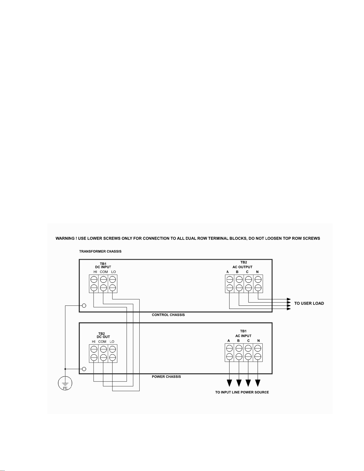
2.6 UNITS WITH TRANSFORMER OPTIONS
The BL5000 series models are available with optional transformer assemblies to
provide different output voltages. These are typically auto-transformers connected to
boost or lower the available 0-135VAC and match the user required load impedance.
T5 options provide a single range while T5D options provide a two-range output. Refer
to table 2-2 for a list of standard output configurations. Engineering specials may allow
other voltages not listed in the table. Refer to any addendum to operating instructions
that may have been provided with the special unit.
The wiring diagram below illustrates the interconnection of a BL5000 with a T5 or T5D
transformer chassis.
Figure 2-3 chassis inter-connect with T5 options

MNL106-676-500 REV-A DATE: 03/23/2022
SECTION THREE
OPERATION
3.1 CONTROLS AND INDICATORS
Table 3-1 below lists the controls, indicators, and other features associated with the
model BL5000 AC power supply. Refer to figure 3-1 & 3-2 for locations.
ITEM
DESIGNATION
COMMENT/DESCRIPTION
1
AC Line ON/OFF
Input circuit breaker.
2
Power indicator
Green indicator lamp for line power
3
Digital Displays
3-digit LED readouts to display output volts, current
and frequency.
4
Display Select Switch
Selects the phase to be monitored by the displays.
Note: output voltage displayed is line to neutral.
5
Voltage Adjust
Multi-turn control provides continuous adjustment
of output voltage. Note: all 3 phases adjust
simultaneously. NOT INCLUDED on fixed voltage
versions.
6
LED Indicators
LED indicators for: Over Temp, Overload, or
Constant Current.
7
OUTPUT switch
Controls internal relay for application of AC output
to user load.
8
PHASE ADJUST trimmers
& LINE DROP COMP trimmers
Front panel “trimmers” that allow fine adjustment of
phase-to-phase angle and regulation over usable
frequency range. See operating instructions for
adjustment instructions.
9
FREQUENCY ADJUST
Multi-turn control provides continuous adjustment
of output frequency. Note: all 3 phases adjust
simultaneously. NOT INCLUDED on fixed voltage
versions.
10
TB2, Rear Panel AC Output
AC output terminal block.
11
TB1, AC Line input
AC input terminal block. See section 2 on input
wiring.
12
Remote interface
Analog remote control or optional RS-232 or IEEE-
488 type computer interface.
13
DC inter-connect (TB2 on input
chassis & TB1 on control unit.)
Connect DC cables between power and control
unit chassis. Caution! 500VDC high voltage.

MNL106-676-500 REV-A DATE: 03/23/2022
FIGURE 3-1 CONTROLS AND INDICATORS BL5000 MODEL SERIES
(FRONT VIEW)
1
2
3
4
5
6
7
8
9

MNL106-676-500 REV-A DATE: 03/23/2022
FIGURE 3-2 BL5000 MODEL SERIES
(REAR VIEW)
10
11
12
13
13

MNL106-676-500 REV-A DATE: 03/23/2022
3.2 OPERATING INSTRUCTIONS
1. Connect the unit to a source of AC power within the rated operating range for this
equipment. See sections 1 and 2 of this document.
2. Connect a suitable load to the AC output terminals (see section 2).
3. Set the output switch to off (recommended).
4. Set the front panel breaker to “ON”.
5. At this point, the front panel display will indicate some value and the sound of
cooling fans will be evident. The unit is now ready to use.
6. To energize the load, set the VOLTS and FREQ controls to provide the desired
output voltage and frequency. Note these controls are multi-turn types. If fitted with a
locking device (option L), make sure the device is un-locked prior to attempting
adjustments. Set the OUTPUT switch to “on” to connect the load. Set the load on
(assuming the load has its own switch or enabling device).
7. During operation, the METER SELECT switch can be set to display the voltage and
current of each phase. The meter displays line to neutral voltages and phase current.
8. To shut down, set the OUTPUT switch off, set the VOLTS control fully
counterclockwise, and set the front panel breaker to the OFF position. NOTE: No
damage to the power supply will occur if this procedure is not followed, however, this
sequence will provide a transient free output during switch on/off.
It is permissible to use the OUTPUT switch to turn the load on and off, however, certain
loads can cause the internal relay contacts to wear prematurely. This is especially true
for loads with capacitive or other high in-rush currents. When in doubt, use the
procedure outlined above. This procedure will provide a transient free output and
prolong the internal relay contact life.
It is also possible to have the output voltage set at zero, and then to turn on the
OUTPUT switch. The voltage can then be increased to the required operating point by
adjusting the VOLTS control clockwise. This method works best with linear loads and
may be desirable for certain applications (variable voltage versions only).
ADJUSTMENT OF LINE DROP COMPENSATION
This model provides a means of compensating for load current related voltage drops
associated with the output wiring. A LINE DROP COMP trim is located on the control
chassis front panel. One trimmer is provided for each phase. To adjust, proceed as
follows detailed in the following:
Other manuals for BL5000 Series
1
This manual suits for next models
10
Table of contents
Other BEHLMAN Power Supply manuals

BEHLMAN
BEHLMAN BL20000 Series Use and care manual

BEHLMAN
BEHLMAN PF1350 Series Use and care manual

BEHLMAN
BEHLMAN P1351 Use and care manual

BEHLMAN
BEHLMAN BL3300 Series Use and care manual

BEHLMAN
BEHLMAN PF1352 Series User manual

BEHLMAN
BEHLMAN BL15000 Series Use and care manual

BEHLMAN
BEHLMAN P1350 Use and care manual

BEHLMAN
BEHLMAN BL10000 Series Use and care manual


