BEHLMAN BL3300 Series Use and care manual

USER'S GUIDE AND
TECHNICAL REFERENCE
AC SOURCE
BEHLMAN MODEL BL3300 SERIES
PART NUMBER: _____________
MODEL _____________________
FOR SERVICE ASSISTANCE
CONTACT BEHLMAN
CUSTOMER SERVICE DEPARTMENT
PHONE TOLL FREE 1-800-874-6727
OR WRITE
BEHLMAN
CUSTOMER SERVICE DEPARTMENT
80 CABOT COURT
HAUPPAUGE, NY 11788
PHONE: (631) 453-0410
FAX : (631) 951-4341
FOR SALES INFORMATION:
PHONE: (631) 435-0410
USA : (800) 874-6727
FAX : (631) 951-4341
DATE:01/28/2013 REV. D

BL3300 SERIES MANUAL 01/28/2013
CLAIM FOR DAMAGE IN SHIPMENT
Under the FOB factory terms of sale, ownership and responsibility are transferred to the customer when the
equipment leaves the factory. Each Behlman equipment is shipped from the factory in proper operating
condition.
Immediately upon receiving equipment, unpack and inspect it for evidence of damage incurred in shipment.
File a claim with the freight carrier if the equipment has been damaged in any way or it fails to operate
properly. Forward a copy of the damage claim report to Behlman. Include the model number, serial number
and date the shipment was received. Behlman will advise the disposition of the equipment and will arrange
for necessary repair or replacement.
RETURNING EQUIPMENT TO FACTORY
Do not return equipment to the factory without prior authorization from Behlman.
A RETURN MATERIAL AUTHORIZATION NUMBER (RMA) is required to return equipment.
This equipment, like all precision electronic equipment, is susceptible to shipping damage. It contains heavy
magnetic components as well as delicate electronic components.
If equipment is returned without prior authorization, the shipment will be refused, the customer being liable
for all shipping, handling and repair costs.
When packing for reshipment, use the original shock absorbent material and shipping container to preclude
damage to the equipment.
Insure that the return authorization numbers (RMA) is available on the container for identification.
SHIPPING INSTRUCTIONS
RACK MOUNTED UNITS
1) Box (es) must be double wall with minimum 350 lbs. bursting test.
2) Box (es) must provide for a minimum of 3to 4 inches of clearance around sides, top and bottom of
unit.
3) When packing unit, utilize either a foam-in-place system or high density foam. Clearance provided
for above must be completely filled with foam.
FAILURE TO COMPLETELY SECURE UNIT IN BOX WILL ALLOW
MOVEMENT DURING SHIPPING, RESULTING IN DAMAGE.
4) Secure box (es) to pallet (s). This is necessary to insure proper handling and protection during
shipping.
5) Place the following warning label on box (es)
DO NOT STACK
6) Ship unit (s) using a freight cargo carrier; air or ground.
CABINET MOUNTED UNITS
Cabinet mounted units require that a special crate be used. The crate should be manufactured of plywood
(3/8" or thicker) and reinforced (using 1 x 3 or larger pine) on all edges. The unit must be firmly secured to
the crate’s base. The crate must be shock mounted to avoid damage during shipping. Detail drawings for
Behlman's crates are available upon request.

BL3300 SERIES MANUAL 01/28/2013
SAFETY SUMMARY
The following safety precautions must be observed during all phases of operation,
service, and operation of this equipment. Failure to comply with these precautions
or with specific warnings elsewhere in the manual violates safety standards
associated with the design and intended use of this equipment.
GROUND THE EQUIPMENT
To minimize shock hazard, the equipment chassis(s) must be connected to an electrical
safety ground. This equipment is supplied with a three conductor line connection for single
phase applications and a five wire connection for three phase applications. Both types
include an earth terminal intended for safety ground connections. In addition, installation
sites may require neutral to earth connections as per NEC section 250 ( National Electrical
Code ). Refer installation to licenced electrician or other qualified personnel.
DO NOT OPERATE IN EXPLOSIVE ATMOSPHERE
Do not operate the equipment in the presence of flammable gases or fumes. Operation of
any electrical instrument in such an environment constitutes a definite safety hazard.
KEEP AWAY FROM LIVE CIRCUITS
Operating personnel must not remove equipment covers. Component replacement and
internal adjustments must be made by qualified maintenance personnel. Do not replace
components with power applied. Under certain conditions, dangerous voltage may exist
even with the power removed. To avoid injuries, always disconnect power and discharge
circuits before touching them.
DO NOT SERVICE OR ADJUST ALONE
Do not attempt internal service or adjustment unless another person, capable of rendering
first aid and resuscitation is present .
DO NOT SUBSTITUTE PARTS OR MODIFY INSTRUMENT.
Because of the danger of introducing additional hazards, do not install substitute parts or
perform any unauthorized modification to this equipment. Contact Behlman Electronics for
proper replacement parts and specific service information.
!DANGEROUS PROCEDURE WARNINGS
Warnings will precede potentially dangerous procedures in this manual. Instructions
contained in the warning must be followed.

BL3300 SERIES MANUAL 01/28/2013
WARRANTY CERTIFICATE
Behlman Electronics, Inc. warrants to the original purchaser, for a period of one (1) year from the shipment
from Behlman, each item to be free from defects in material and workmanship. Behlman’s obligation and the
Purchaser’s sole remedy for any breach or violation of this agreement is limited to adjustments, repair or
replacements for parts which have been promptly reported by the Purchaser as having been in its opinion,
defective and so found by Behlman upon inspection. All replacement parts will become the property of
Behlman on an exchange basis. This warranty will not apply if such adjustment repair or parts replacement
is required because accident, neglect, misuse, failure of environmental controls, transportation damage or
causes other than normal use. Batteries are warranted for 30 days from date of purchase.
If during the warranty period a defect should impair the performance of the unit, Behlman agrees, at its
option, to repair or replace the unit or its defective components F.O.B. Behlman at 80 Cabot Court,
Hauppauge NY 11788 or at another Behlman service facility at Behlman’s option. To obtain service under
this warranty, the original Purchase shall notify Behlman at the above address or by telephone at 631-435-
0410 and provide information about the defect or impairment of performance. Behlman with then supply the
Purchaser a Return Material Authorization (RMA) number. This number must be attached to the equipment
sent back for warranty repair. Equipment must be shipped back to Behlman prepaid. No collect shipments
will be accepted.
Behlman shall be excused from supplying warranty service if the unit’s case has been open or if the unit has
been subject to unauthorized repair. All service outside the scope of this warranty shall be paid for by the
Purchaser at Behlman’s rates in effect at the time of this repair. Behlman will not perform any repairs outside
of the warranty without written authorization by the Purchaser. If the repair is a warranty repair, Behlman will
ship the unit back to the Purchaser, by a method determined solely by Behlman, prepaid. If the Purchaser
requests, any other means of transportation it shall be at the Purchaser’s expense.
The use of the equipment shall be under the Purchaser’s exclusive management and control. The Purchaser
will be responsible for assuring the proper installation, use, management and supervision of the equipment.
Behlman will not be liable for personal injury or property damage.
The forgoing warranties are in lieu of all other warranties, expressed or implied including without limitation
warranties of merchantability and fitness for purpose.
In no event shall Behlman be liable for loss of profits, loss of use, or any indirect, consequential or incidental
damages. Purchaser agrees that Behlman will not be liable for any damages caused by the Purchaser’s failure
to fulfill any of the Purchaser’s responsibilities set forth herein.

BL3300 SERIES MANUAL 01/28/2013
TABLE OF CONTENTS
BEHLMAN AC SOURCE, MODEL SERIES BL3300
SECTION
1 INTRODUCTION
1.1 General Description
1.2 Options
1.3 Special Units
1.4 Specifications
2 UNPACKING AND INSTALLATION
2.1 Unpacking
2.2 Installation
2.3 Protective Earth Connection
2.4 3 Phase Input Requirements C1 - C6
2.5 Input Considerations for Single Phase Units C8/C9
3 OPERATION
3.1 Controls and Indicators
3.2 To Operate The Equipment
3.3 Shutdown Procedure
3.4 Adjusting Line Drop Compensation Trims
3.5 Remote Programming ( analog )
3.6 External Sync
3.7 Operational Considerations
4 MAINTENANCE AND ADJUSTMENTS
4.1 Maintenance
4.2 Adjustments
4.3 Phase Adjustment
5 THEORY OF OPERATION
5.1 General
5.2 Input Power
5.3 Control Chassis
5.4 Motherboard
5.5 Output Invertor
5.6 Metering
5.7 Miscellaneous

BL3300 SERIES MANUAL 01/28/2013
TABLE OF CONTENTS (cont)
BEHLMAN AC SOURCE, MODEL BL3300
DESCRIPTION DOCUMENT NUMBER
6 PARTS LIST AND DRAWINGS
ControlChassis(Assembly) ........................106-909-005
ControlChassis(Schematic) .......................106-951-011
Motherboard (Schematic) ..........................106-948-000
Phase Control - 3
N
(Schematic) .....................106-942-000
Power Chassis ( Assembly) 3 phase .................107-348-000
Power Chassis (Assembly) 1 phase .................107-348-001
Power Chassis ( schematic 3 phase) .................107-414-000
Power Chassis ( schematic 1 phase) .................107-300-001
APPENDIX
A IGBTDriver.....................................A-1
B IEEE- 488 Remote Interface Operation ...............B-1
C RS232 Remote Interface Operation ..................C-1

1
BL3300 SERIES MANUAL 01/28/2013
SECTION 1
INTRODUCTION
1.1 GENERAL DESCRIPTION
The Behlman AC Source models (table 1) are sophisticated ac power supplies.. These devices
convert the available utility power to a voltage and frequency required by the end user.
Regulation and control of the AC power is also provided by these devices. Each of the models
provide independent verification of operating voltage, current, and frequency values thereby
lessening the need for external measuring devices.
All Behlman BL series power supplies are based on high frequency, pulse width modulated,
IGBT technology. This arrangement provides a highly efficient power conversion scheme in a
compact size. These devices are used in many applications including; avionics testing,
production ATE, processes control, research and development, and anywhere ac power ( other
than utility power) is required.
1.2 OPTIONS
The Behlman 3300 series is available with many input and output options. Some of the output
options require additional transformer chassis for higher voltages. The table and list below
summarize these options. Any of the models can include all or any combination of the available
options if desired.
TABLE 1. BEHLMAN 3300 SERIES MODELS
MODEL INPUT
VOLTAGE
(ac)
OUTPUT
VOLTAGE
(ac)
BL3300C-1 120V/208V 0 - 135V, 3N
BL3300C-2 220V/380V 0 - 135V, 3N
BL3300C-3 277V/480V 0 - 135V, 3N
BL3300C-4 200V )0 - 135V, 3N
BL3300C-5 346V/600V 0 - 135V, 3N
BL3300C-6 230V/400V 0 - 135V, 3N
BL3300C-7 240V/415V 0 - 135V, 3N
BL3300C-8/9 120/240V 1N* 0 - 135V, 3N
*Note : C8/C9 single phase input requires two 7 inch chassis all others are
comprised of one 7" chassis and one 3.5" chassis except options.
OPTIONS: Add E to the dash number for extended frequency range.
Add I to the dash number for Remote GPIB IEEE-488/RS232 Interface.
Add L to the dash number for front panel locking controls (VOLTS, FREQ)
Add S to the dash number for chassis slides.
Add T3 to the dash number for voltage ranges 0-300V L/N add 3.5" chassis
Add T3D to the dash number for voltage ranges 0-135/300 add 3.5" chassis
Add T3DT to the dash number for voltage ranges 150/300 add 3.5" chassis

2
BL3300 SERIES MANUAL 01/28/2013
1.3 SPECIAL UNITS
BEHMAN has produced many special versions of the BL series supplies over the years and will
continue to offer specials to our customers. These specials are usually in the form of customer
specified output voltages, special control functions, or special waveforms ( square wave is one
example ). With this in mind it should be noted some of the information ( including
specifications) contained in this manual may not be applicable to the unit shipped.
All special units will be designated by a four digit “engineering” number following the model
number indicated on the power supply rating tag ( identification label). This number refers to
an engineering file that contains modification instructions and (or) drawings related to the
special unit. This information may or may not be included in this manual. Unless specified by
purchase contract, the decision to include this information in this manual is reserved solely by
Behlman .
All special unit manuals will include an addendum that explains the modification and refers to
any special operating considerations warranted by the modification. Any exceptions to standard
unit specifications will also be addressed by the addendum. When ordering replacement or
additional manuals, make sure to check the ID label for the power supply so that any
addendums may be included.
.

3
BL3300 SERIES MANUAL 01/28/2013
ALL MANUAL ADDENDUMS WILL FOLLOW THIS PAGE

4
BL3300 SERIES MANUAL 01/28/2013
1.4 SPECIFICATIONS
INPUT POWER
Voltage: see chart on preceding page
Frequency: 47-63 Hz.
OUTPUT POWER
Voltage: 0-135 Vac, 3N*
Frequency: 45-500 Hz ( 45 -1000 optional )
Maximum Power: 3300 VA
Maximum Current: 7.5 amperes per phase
Current Crest
Factor: 3:1.
Power Factor: 100% of rated output into any power factor load.
Distortion: 1.5% maximum T.H.D. (measured at full load, 100 Vac, 50 Hz).
Load Regulation: ±0.7% from no load to full load.
Line Regulation: ±0.1% for ±10% of line change.
Efficiency: 85-90% ( with 3 phase input )
Metering: Voltmeter Accuracy: +/-2% of range +/-1 digit (1 volt resolution )
Ammeter accuracy: +/2% of range +/1 digit ( 0.1 amp resolution)
Frequency Meter: +/-2 % of range +/- 1 digit ( 1 Hz resolution)
MECHANICAL
Dimensions: 19 in. wide, 17.5in. high, 22 in. deep .
Weight: 150 lbs.
Operating
Temperature: 0°C to 55°C (32°F to 131°F).
* Voltage may vary. See option list, page 1.

5
BL3300 SERIES MANUAL 01/28/2013
SECTION 2
UNPACKING AND INSTALLATION
2.1 UNPACKING
After unpacking the AC Source (unit), carefully conduct a thorough inspection of controls, indicators
and chassis. If the unit shows signs of damage, do not attempt to operate. File a damage claim with
the carrier responsible. Notify Behlman immediately.
2.2 INSTALLATION
!WARNING
INSTALLATION AND OPERATION OF THIS EQUIPMENT EXPOSES VOLTAGE AND CURRENTS
THAT ARE HAZARDOUS. INSTALLATION MUST BE PERFORMED BY QUALIFIED PERSONNEL
ONLY.
1) This unit is intended to be mounted in an EIA standard 19 inch rack cabinet. This model consists of
two chassis. The input chassis houses the input transformer rectifiers and filters. The output of this
chassis is the DC operating voltages of +/-250VDC centered on the GND or common. The second
chassis ( control chassis ) houses the output inverters and all other active electronics. The system
is designed and tested with the control chassis in the top position. The keeps the maximum weight
at the bottom and provides the lowest center of gravity. T3 option unit have an additional outptu
chassis that should be mounted in the lowest position due to weight.
IMPORTANT
The chassis must have bottom support when mounting in a rack or a cabinet. Do not attempt to mount by
front panels only. These models pull cool air in through the side panels and exhaust heated air to the rear.
These units, when stacked, require proper cooling air circulation, one inch clearance between units and a
six inch clearance at the rear of the units. Rack enclosures must be ventilated.
2) Ensure that the line circuit breaker and all other unit controls are in the OFF position before
connecting input power.
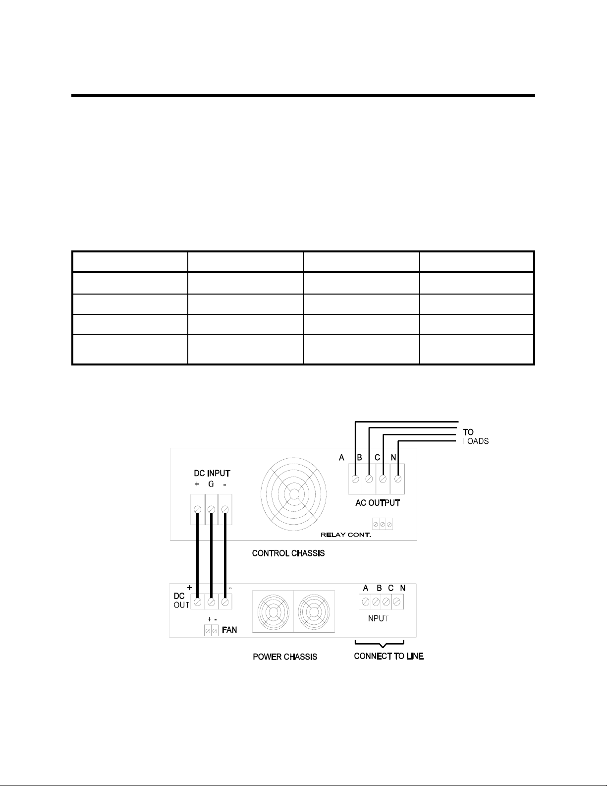
3) Connect 3 phase units as follows: ( refer to inter-connect diagrams provided on following pages.)
a) INPUT POWER- Connect 47-63 Hz, power lines to the AC INPUT terminals designated:
NA, NB, NC, and NEUTRAL . These are located on the rear of the input chassis and
designated as TB1. These connections require #10 ( 0.19") inside diameter ring lugs.
b) OUTPUT POWER- Output power lines are connected to the NA, NB, NC, and NEUT
provided on the AC OUTPUT terminal strip on the rear of the control chassis. For T3
option units this terminal block is on the output chassis. These connections require 1/4"
inside diameter ring lugs. Use screws designated “WIRE THIS SIDE” only, removing the
other screws will cause mounting hardware to become loose and may fall into the unit.
c) DC Interconnection between chassis:
Connect the HI, GND, and LOW DC output terminals of the power chassis to corresponding
DC input of the control chassis. Use the cables provided DO NOT USE LONGER WIRES.
Connect the two chassis together by connecting their chassis studs with cables provided. The
installation site protective earth ( safety ground ) should be connected to the rear panel
stud(s).

6
BL3300 SERIES MANUAL 01/28/2013
SECTION 2
UNPACKING AND INSTALLATION
! WARNING
2.3 PROTECTIVE EARTH CONNECTION
This equipment is provided with a protective earth connection as one level of protection against
electrical shock hazards. The metallic chassis of this equipment must be connected to the installation
site safety earth. This is typically the green/yellow wire supplied in most line cords. This is in addition
to the input neutral. Three phase units utilize a four wire input plus the safety earth. Unless stated
otherwise, all 3 phase inputs are of a “WYE” configuration. The Neutral connection is required for
input harmonic reduction and EMI filter return. The unit may be operated without the neutral however
this is not recommended.
IMPORTANT NOTE:
If this unit is to be installed as part of a permanent power source with wiring distributed in a building
the user is responsible for conformance to local electrical codes. The National Electrical Code
(NEC)section 250 requires that all separately derived AC power sources ( generators, invertors, etc.
) must have one conductor tied to earth. This is similar to the concept of the neutral conductor in
domestic power distribution systems. This connection may be provided by connecting the input neutral
to the output neutral ( neutral carried through )or connecting the output neutral to the chassis ground.
The output neutral of this equipment is internally isolated from the input neutral. Consult local codes
and a qualified electrician.
2.4 3 PHASE INPUT POWER REQUIREMENTS
The BL3300 series power supplies within the model number range C2 to C6 require the use of “back-
up” fuses to provide the required protection when operating from line to line voltages above 277 volts.
This is due to the interrupt rating of the circuit breaker used. The fuses are located on the front panel
of the input power chassis. The front panel circuit breaker is employed as a switch only for these
units. Fuses must be replaced with the same type and rating only.
! WARNING
REMOVE INPUT POWER BEFORE REMOVING OR REPLACING FUSES
FUSE REPLACEMENT IS DESCRIBED ON THE FOLLOWING PAGE
7
BL3300 SERIES MANUAL 01/28/2013
SECTION 2
UNPACKING AND INSTALLATION
2.4 3 PHASE INPUT POWER REQUIREMENTS ( continued )
The chart below indicates the proper fuse based on the model number of the power supply. This chart can
also serve as a guide for sizing the input service to the unit. Note: refer to the following section for C8/9
singe phase units.
The following lists should be used to select the proper line fuse size for the model numbers shown. The
selections are based on nominal line voltages and maximum output power. All fuses carry a 600 Vac rating.
DO NOT substitute any other fuse type.
MODEL # L-L VOLTAGE FUSE SIZE PART NUMBER
BL 3XXX - C2 380V 12 AMP / 600V 108-201-021
BL 3XXX- C3 480V 10 AMP/ 600V 108-201-020
BL 3XXX- C5 600 V 10 AMP/ 600V 108-201-020
BL 3XXX- C6 400V 12 AMP/ 600V 108-201-020
Inter-connect diagram for standard 3 phase input.

8
BL3300 SERIES MANUAL 01/28/2013
SECTION 2
UNPACKING AND INSTALLATION
2.5 INPUT POWER CONSIDERATIONS FOR SINGLE PHASE INPUTS ( C8 and C9 units )
This device utilizes a single phase, full wave, rectifier followed by a capacitive filter to provide main
operating voltages. This type of arrangement produces an input current with a high harmonic content.
These harmonics contribute to the input current requirement but do not contribute to the output
power. This fact equates to the input of this device having a low power factor. Power factor is the ratio
of input volt-amperes ( reactive power) to real power (watts) consumed. The power factor of a single
phase rectifier ( with capacitive filter) is on the order of 0.6 to 0.8 depending on the line impedance
and condition of the capacitors used ( typically electrolytic).
The power factor of this unit should not be confused with the stated output efficiency of 80%. This
rating deals with the inverter efficiency and is measured with a 3 phase input that yields a power
factor closer to 0.95. In order to select the proper electrical service size for this unit, the total
power consumption and input power factor must be considered. What follows below is a typical
example.
The following is assumed:
Output power is in real watts at an efficiency of 80%.
Total power equals 3000 W / 0.8 = 3750 watts
Assuming a worst case power factor of 0.6 a multiplication factor of 1/PF can be used to find the
total input volt-amperes
3750 x 1.66 = 6225 VA
If operating at 120 Vac input ( 108 @ 10% low line ) then the input current requirement is :
6225 / 108V = 57.6 amperes
The actual input current will be somewhat lower and depends on the line impedance in series with
the power supply. Also, if the load being powered is reactive, the actual input current could be
considerably lower. Testing under actual conditions may yield results allowing the use of a
smaller service. Consultation with an experienced electrician or electrical engineer is highly
recommended.
9
BL3300 SERIES MANUAL 01/28/2013
SECTION 2
UNPACKING AND INSTALLATION

10
BL3300 SERIES MANUAL 01/28/2013
SECTION 2
UNPACKING AND INSTALLATION
2.5 INPUT POWER CONSIDERATIONS FOR SINGLE PHASE INPUTS ( C8 and C9 units )
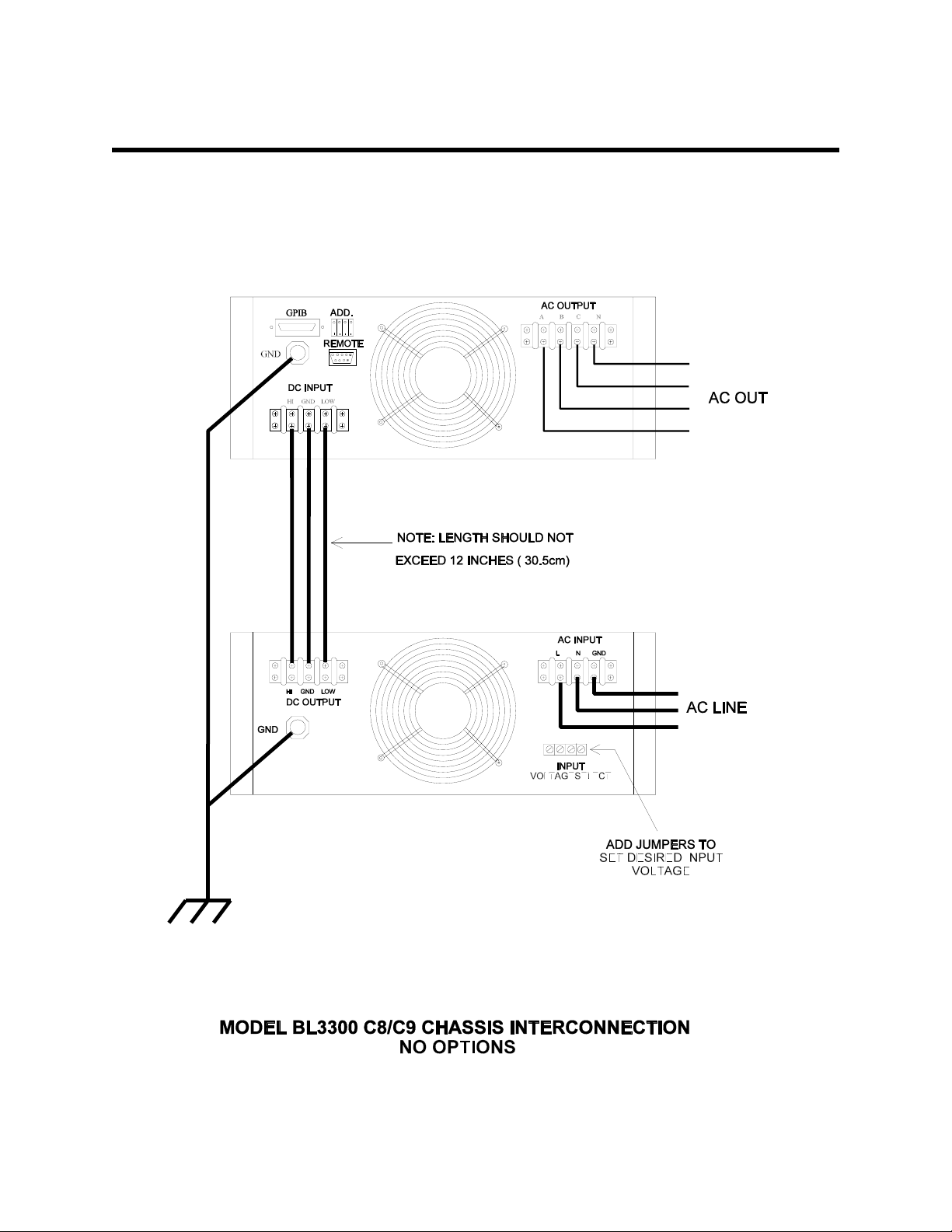
2.5.1 SETTING THE INPUT VOLTAGE RANGE
This device is equipped with a dual primary input transformer. These windings may be series
connected for a 240 nominal input or in parallel for a 120 nominal input. Internal taps allow finer
adjustment and are set at the factory. The diagram below illustrates the voltage selecting terminals
located on the rear of the single phase input power chassis. Replace safety covers after wiring.
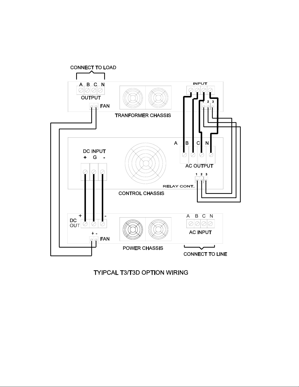
2.6 UNITS WITH T3 OR T3D OPTIONS
The diagram of figure 2-2 on the following page illustrates chassis inter-connection for units provided
with the T3 or T3D options. The T3D units are dual range versions of the standard T3 type. As shown
in figure 2-2 , this option includes an additional 3.5 inch high chassis to house the external
transformers and range relay for T3D units. This is referred to as the transformer chassis. The output
relay that controls application of power to the load is also moved to the transformer chassis. Additional
inter-wiring is required to bring relay and fan power to the transformer chassis. Units supplied with T3
options will include additional terminal blocks with 6/32 hardware for this purpose. The location may
vary for special units
Units supplied with T3 options may vary slightly depending on actual customers requirements.
Units with a 0 to 270 Vac or 0 to 300 Vac are considered standard. Units supplied with other
voltages will be assigned a 4 digit engineering number. T3 units require some special operating
considerations. Refer to section 3 of this manual for additional operating consideration for T option
units.
11
BL3300 SERIES MANUAL 01/28/2013
FIGURE 2-2

12
BL3300 SERIES MANUAL 01/28/2013
SECTION 3
OPERATION
!WARNING
This equipment involves the use of voltages and currents that can be hazardous. Only qualified
personnel should be allowed to operate or service it. The top cover(s) must always be in place
during operation.
3.1 CONTROLS AND INDICATORS
Table 1 lists the controls and indicators used on the different models of the AC Source. The table also
includes their function. Figure 3-1 locates these front panel controls and indicators. Also shown are
the rear panel REMOTE PRGM connector, two terminal strips, cooling fan, and a GND stud.
3.2 TO OPERATE THE EQUIPMENT
1) Ensure that line circuit breaker and OUTPUT switch are set to OFF.
2) Connect suitable load across output terminals. (Do not exceed rating of unit.)
3) Set line circuit breaker of power chassis to ON (cooling fan noise should become evident).
4) Rotate VOLTS control to desired voltage. ( for T3D units, set the range switch as required ).
5) Rotate FREQ control to desired frequency.
6) Set OUTPUT switch to ON to energize load.
NOTE
It is permissible to energize a load gradually by setting the OUTPUT
switch ON and rotating the VOLTS control from zero or a low voltage
position up to the voltage desired.
3.3 SHUTDOWN PROCEDURE
1) Set OUTPUT switch to OFF.
2) Set VOLTS control fully counter- clockwise.
3) Set the line circuit breaker to OFF. NOTE: once turned off, a period of 30 seconds is required to
reset the soft start circuit. Failure to do so may blow input fuses due to high in-rush current
when power is reapplied.
3.4 ADJUSTMENT OF LINE DROP COMPENSATION AND PHASE ANGLES
The BL series of power supplies provide a means to compensate for load related effects and a means
to trim the phase angles. A “Line Drop Comp” trim is provided for each phase. Phase trim pots are
provided to adjust the angle from phase A to Phase B ( A-B ) and between phase B and phase C (B-
C).The setting of the line drop comp is done at the factory with a full resistive load. The phase angles
are factory set so the B lags A by 120 electrical degrees and C lags B by 120 electrical degrees.
These adjustments should be periodically confirmed. See section 4.2.10 for adjustment procedures.

13
BL3300 SERIES MANUAL 01/28/2013
Table 3-1 Controls and Indicators
REF# CONTROL / INDICATOR FUNCTION / DESCRIPTION
1LINE CIRCUIT BREAKER Located on input chassis, applies or removes input
line power.
2 CONSTANT CURRENT indicator L.E.D. indicates protective circuit is activated to
limit output current.
3FREQcontrol Multi-turn control provides continuous adjustment
of output frequency.
4OUTPUTswitch Controls internal relay to connect and dis-connect
output voltage to load.
5 OVERLOAD LATCH indicator L.E.D. indicates protective circuit is activated due
to output short circuit. Line power must be cycled of
for 30 seconds to reset power supply.
6 OVER TEMP indicator. L.E.D. indicates protective circuit is activated due
to excessive internal temperature. automatic reset
once temperature return to a safe value.
7Digital Panel Meters VOLTS: displays output voltage (RMS)
AMPS: displays output current (RMS)
FREQ: displays output frequency (Hz)
8 VOLTS control Multi-turn control provides continuous adjustment
of output voltage.
9 LINE DROP COMP. trim pots Allows for correction of output voltage that is
proportionate to current. Used to trim out resistive
drops due to load wiring. See text.
10 RANGE switch Optional for units with T3D option only. select one
of two output voltage ranges.
11 TB1 DC power connector Connects to +/- 250Vdc from input chassis.
DC inter-connect wires supplied with unit.
12 TB2 AC output connector terminal block for connection to output load.
Requires 1/4" hardware.
13 REMOTE PRGM connector Optional computer interface. May be either RS-232
( DB9 ) or IEEE-488 type connector.
14 GND ( Protective Earth ) 1/4 “ stud for connecting safety earth. ( a.k.a.P.E.)

14
BL3300 SERIES MANUAL 01/28/2013
Table of contents
Other BEHLMAN Power Supply manuals

BEHLMAN
BEHLMAN P1351 Use and care manual

BEHLMAN
BEHLMAN PF1350 Series Use and care manual

BEHLMAN
BEHLMAN PF1352 Series User manual

BEHLMAN
BEHLMAN BL20000 Series Use and care manual

BEHLMAN
BEHLMAN BL10000 Series Use and care manual

BEHLMAN
BEHLMAN BL5000 Series Use and care manual

BEHLMAN
BEHLMAN BL15000 Series Use and care manual

BEHLMAN
BEHLMAN P1350 Use and care manual


