Beissbarth Start Line MT 601 D User manual
Start Line MT 601 D
Radwuchtmaschinen
Wheel Balancers
de
Originalbetriebsanleitung
Radauswuchtmaschine
en
Original instructions
Wheel Balancing Machine
fr
Notice originale
Banc d‘équilibrage de roues
es
Manual original
Máquina de equilibrado de ruedas
it
Istruzioni originali
Equilibratrice per ruote
pt
Manual original
Máquina de balanceamento de rodas

1 695 600 538 2016-07-27|
| Start Line MT 601 D | 23 en
Contents English
1. Symbols used 24
1.1 In the documentation 24
1.1.1 Warning notices -
Structure and meaning 24
1.1.2 Symbols in this documentation 24
1.2 On the product 24
1.3 Safety Instructions 24
2. User information 25
2.1 Important notes 25
2.2 Safety instructions 25
2.3 Electromagnetic compatibility (EMC) 25
3. Product description 25
3.1 Intended use 25
3.2 Prerequisites 25
3.3 Device description 26
3.4 Accessories supplied 26
4. Initial commissioning 27
4.1 Unpack the MT 601 D 27
4.2 Setting up the MT 601 D 27
4.3 Fitting the wheel-guard hood 27
4.4 Power socket 28
4.5 Checking direction of rotation 28
4.6 MT 601 D calibration 28
5. Fitting and removing flange 29
5.1 Fitting flange 29
5.2 Removing flange 29
6. Fitting and removing wheel 29
6.1 Clamping the wheel 29
6.1.1 Clamping on correct side 29
6.1.2 Clamping on opposing side 30
6.1.3 Clamping with special flange 30
6.2 Removing the wheel 30
7. Program layout 31
7.1 Display 31
7.2 Control buttons 31
7.3 Keystroke combination for changing between
functions 32
7.4 Balancing programs 32
7.5 Standard program for input of rim data 32
7.6 Input of rim data for ALUS 34
8. Balancing the wheel 34
8.1 Occupied area 34
8.2 Measuring imbalance 35
8.3 Attaching balance weights 35
8.3.1 Standard procedures for clip-on weights
and adhesive weights 35
8.3.2 ALUS balancing mode 35
8.3.3 Splitting the balance weights (HID
program) 35
8.4 Attaching the clip-on weights 36
8.5 Attaching adhesive balance weights 36
9. Imbalance minimization 37
10. Adjustment 37
11. Faults 38
12. Service 39
12.1 Cleaning and Maintenance 39
12.2 Spare and wearing parts 39
12.3 Self-calibration 39
12.3.1 Self-calibration of system 39
12.3.2 Automatic self calibration of the rim-
distance gage 39
12.4 Self-inspection 40
12.5 Structure and setting of pressure sensor 40
12.6 Adjusting the belt tension 40
12.7 Changing the fuse 40
13. Decommissioning 41
13.1 Temporary shutdown 41
13.2 Change of location 41
13.3 Disposal and scrapping 41
13.3.1 Substances hazardous to water 41
13.3.2 MT 601 D and accessories 41
14. Technical parameters 41
14.1 MT 601 D 41
14.2 Size and weight 41
14.3 Operating range 41
14.4 Temperatures and operating range 41

1 695 600 538 2016-07-27|
24 | Start Line MT 601 D | Symbols useden
1.3 Safety Instructions
Please read the manual before operation.
Please wear eye protection.
Rotating equipment, exercise caution.
1. Symbols used
1.1 In the documentation
1.1.1 Warning notices -
Structure and meaning
Warning notices warn of dangers to the user or people
in the vicinity. Warning notices also indicate the con-
sequences of the hazard as well as preventive action.
Warning notices have the following structure:
Warning
symbol
KEY WORD – Nature and source of hazard!
Consequences of hazard in the event of fail-
ure to observe action and information given.
¶Hazard prevention action and information.
The key word indicates the likelihood of occurrence and
the severity of the hazard in the event of non-observance:
Key word Probability of
occurrence
Severity of danger if in-
structions not observed
DANGER Immediate impend-
ing danger
Death or severe injury
WARNING Possible impending
danger
Death or severe injury
CAUTION Possible dangerous
situation
Minor injury
1.1.2 Symbols in this documentation
Symbol Designation Explanation
!Attention Warns about possible property damage.
iInformation Practical hints and other
useful information.
1.
2.
Multi-step
operation
Instruction consisting of several steps.
eOne-step
operation
Instruction consisting of one step.
Intermediate
result
An instruction produces a visible inter-
mediate result.
"Final result There is a visible final result on com-
pletion of the instruction.
1.2 On the product
!Observe all warning notices on products and ensure
they remain legible.
Information on the rating plate
Product designation, 10-digit material number; volt-
age (V), setting (Hz), installed load (kW); current (A),
maximum supply pressure (kPa), protection class (IP);
year of manufacture; CE mark; 13-digit material num-
ber and machine model; barcode.
Disposal
Dispose of used electrical and electronic
devices, including cables, accessories and
batteries, separately from household waste.
Prescribed voltage supply
Information on the voltage set and safety warning.
DANGER – Exposure of live parts on open-
ing the MT 601 D!
Risk of (fatal) injury or heart failure from
electric shocks on contact with live compo-
nents (e.g. master switch, printed circuit
boards).
¶Work on electrical installations or equip-
ment is only to be performed by qualified
electricians or trained personnel under the
guidance and supervision of an electrician.
¶Disconnect the MT 601 D from the mains
before opening.
Direction of wheel rotation
Wheel must turn in direction indicated.
(see chapter "Checking the direction of
rotation")

1 695 600 538 2016-07-27|
User information | Start Line MT 601 D | 25 en
2. User information
2.1 Important notes
Important information on copyright, liability and warran-
ty provisions, as well as on equipment users and com-
pany obligations, can be found in the separate manual
"Important notes on and safety instructions for Beissbarth
Tire Equipment". These instructions must be
carefully studied prior to start-up, connection and opera-
tion of the MT 601 D and must always be heeded.
2.2 Safety instructions
All the pertinent safety instructions can be found in
the separate manual "Important notes on and safety
instructions for Beissbarth Tire Equipment". These
instructions must be carefully studied prior to start-up,
connection and operation of the MT 601 D and must
always be heeded.
2.3 Electromagnetic compatibility (EMC)
The MT 601 D satisfies the requirements of the EMC
directive 2004/108/EG.
iThe MT 601 D is a class/category A product as
defined by EN 61 326. The MT 601 D may cause
high-frequency household interference (radio inter-
ference) so that interference suppression may be
necessary. In such cases the user may be required to
take the appropriate action.
3. Product description
3.1 Intended use
The MT 601 D is a wheel balancing machine featuring
mechanical wheel clamping for the balancing of car,
light van and motorcycle wheels with a rim diameter of
10" - 27" and a rim width of 1" - 20".
The MT 601 D is to be used exclusively for this purpose
and solely for the range of applications specified in
these instructions. Any other purpose is not consistent
with the intended use and is therefore not permissible.
iThe manufacturer cannot accept any liability for pos-
sible damage arising from improper use.
3.2 Prerequisites
The MT 601 D must be installed on a flat surface
made of concrete or similar material and anchored in
position.
!An uneven or vibrating surface can lead to inaccu-
rate unbalance measurements.
!Any uneven floors or that do not meet the previously
expressed safety requisites relieve the manufactur-
er from any liability for damages to persons and/or
property.
!1) * These dimensions refer to standard rims (A); for
rims with a special shape (B - C), special accesso-
ries should be used.
A
B
C
Fig. 1: Rim types

1 695 600 538 2016-07-27|
26 | Start Line MT 601 D | Symbols useden
3.3 Device description
Fig. 2: Product introduction
Item Designation Function
1 Display panel Display of measuring results
2 Control panel Operation of the MT 601 D
3 Shelf Shelf for balance weights and accessories.
4 On/Off switch Switching power On/Off
5 Clamping tool holders Attaching spare parts and cones
6 Brake pedal Blocking of wheel while attaching or removing wheel weights
7 Retaining tabs For fastening to the floor
8 flange Fasten wheel.
9 Rim-distance gage
(electronic)
RRecords rim distance and rim diameter.
RDetermines positions for attachment of adhesive balance weights.
10 Wheel guard RProtects operator against flying particles (e.g. dirt, water).
RStarting and stoppin measurement
11 Cover plate Storing & reconditioning the weights
3.4 Accessories supplied
Name Order number
Large flange 0530201001
Small cone 0530201016
Cone 2 0530201037
Cone 3 0530201038
Cone 4 0530201039
Spacer plate, large 020601001
Quick-action clamping nut 020601003
Wrench, waf 12 022102001
Wrench, waf 6 022102002
Wrench, waf 4 022102003
Wrench, waf 3 022102004
Name Order number
Balance weight pliers 022102005
Spring 020701012
Weights100g 022102006
Weights50g 022102010
Weights35g 022102011
Weights10g 022102013
Weights5g 022102027
Measuring compass 020601004
Adhesive weights remover 020601105
Allen key 022102035
hexagon socket head bolt 030201064
1 695 600 538 2016-07-27|
Initial commissioning | Start Line MT 601 D | 27 en
4. Initial commissioning
4.1 Unpack the MT 601 D
1. Remove the steel band and fasteners.
2. Carefully lift off the packaging.
3. Remove the accessories and packaging material
from the packaging unit.
iCheck that the MT 601 D and the accessories are in
proper working order and that there are no visi-
ble signs of component damage. In case of doubt,
do not commission the unit and consult customer
service.
iDispose of the packaging material at an appropriate
collection site.
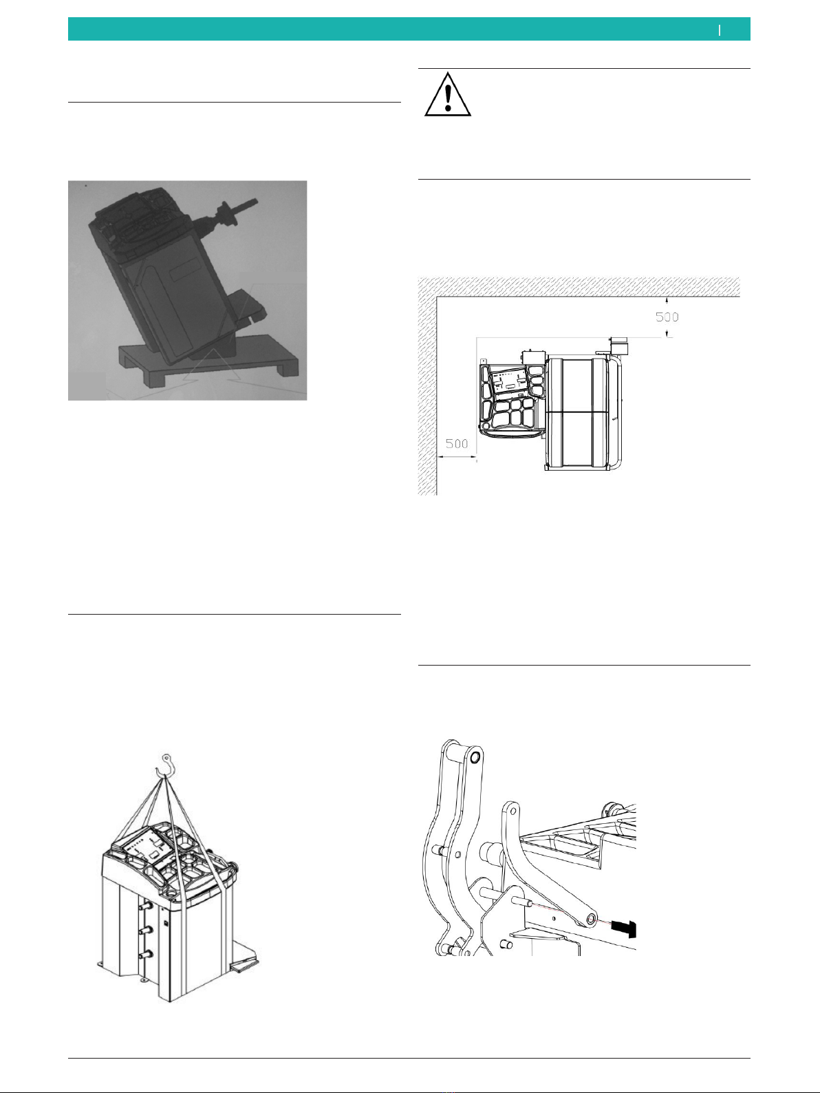
4.2 Setting up the MT 601 D
1. Unfasten locating screw on MT 601 D.
2. Attach hoisting strap as shown in illustration. The
hoisting strap must be at least the same length, and
must have enough load-bearing capacity (at least
100kg).
Fig. 3: Lifting the wheel balancer
Warning of damage or wrong lifting gear
Risk of injury if MT 601 D falls.
¶Please check hoisting strap before
attaching it.
¶Secure the hoisting strap.
¶Lift the MT 601 D carefully.
3. MT 601 D must never be lifted by the flange shaft.
After lifting, set down at prepared installation lo-
cation and pay attention to the minimum specified
distance.
Fig. 4: Wheel balancer installation location
iFor safety reasons, the installation location must be
500mm away from the wall.
4. MT 601 D must be secured to the ground with ex-
pansion bolts. Measuring errors will occur if it is not
fixed firmly.
4.3 Fitting the wheel-guard hood
1. Remove nut from support bracket on the 2 wheel-
guard hoods, then remove the support bracket.
Fig. 5: Unfastening the guard hood

1 695 600 538 2016-07-27|
28 | Start Line MT 601 D | Initial commissioningen
4.4 Power socket
!MT 601 D must not be connected to the power
supply unless its voltage is the same same as that
specified on the rating plate.
1. Check to ensure that power supply is at the same
voltage as specified on the rating plate.
2. Check the usual standard for machines and ensure
that the power connector and power port on cus-
tomer premises both comply with that standard.
3. Connect up to power supply.
4. Connect switch connector of wheel-guard cover.
Fig. 8: Connect switch connector of wheel-guard cover
2. Attaching the wheel-guard hood and hood bracket.
Fig. 6: Fitting the wheel-guard hood
3. Install wheel-guard hood in support and tighten the
screw.
4. Install support bracket 2, then install the plate as
shown in the following Figure.
Fig. 7: Installing the support bracket
4.5 Checking direction of rotation
1. Check whether the MT 601 D is properly connected
to the mains.
2. Switch on the MT 601 D at the on/off switch.
3. Close the wheel-guard hood.
Flange shaft rotates.
!If flange shaft does not rotate, press button <???>.
iIf the direction of rotation is incorrect the MT 601 D
comes to an immediate halt and the error message
ERR 3 is displayed.
4. Check direction of rotation of flange shaft.
iThe correct direction of rotation is indicated by a label
on the right side of the MT 601 D.
4.6 MT 601 D calibration
!Calibration must be performed after initial commis-
sioning.
1. Calibrate the flange.
2. Calibrate rim-distance gage.
3. Calibrate MT 601 D.
4. Perform reference measurement.
iThe calibration is described in the section "Calibra-
tion".

1 695 600 538 2016-07-27|
Fitting and removing flange | Start Line MT 601 D | 29 en
5. Fitting and removing flange
5.1 Fitting flange
1. Actuate pedal.
Flange shaft blocked.
2. Screw lead screw into flange shaft.
3. Install the M14 screw.
Fig. 9: Installing the lead screw
4. Use Allen key to tighten until there is no clearance
between lead screw and flange, i.e. until tight.
"Screw connection established
iInstall until "0" marks on flange shaft and lead screw
are aligned.
5.2 Removing flange
1. Actuate pedal.
Flange shaft blocked.
2. Turn wrench anti-clockwise until lead screw and
flange shaft disconnect from one another.
Fig. 10: Removing flange
6. Fitting and removing wheel
WARNING - wheel may slip!
Risk of crushing of fingers and other body
parts when attaching and removing wheel.
¶Wear protective gloves.
¶Wear safety shoes
¶Do not place finger(s) between wheel and
flange shaft.
¶Heavy wheels should always be handled
by two people.
6.1 Clamping the wheel
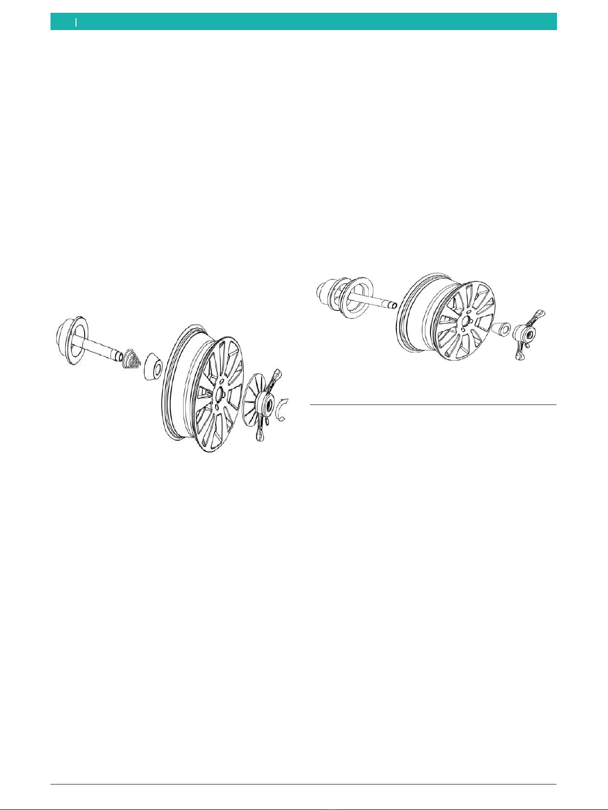
6.1.1 Clamping on correct side
iThe usual clamping method is with aligned sides, a
quick and easy operation suitable for normal steel
rims. This method can only be used on steel rims
where distortion is not serious.
1. Push wheel onto flange shaft with internal face onto
lead screw.
2. Fit suitable cone (small surface facing inwards).
3. Press quick-locking nut, then rotate quick locking
nut on the flange shaft.
4. Release clamping device, then rotate quick locking
nut clockwise.
Fig. 11: Install wheel on correct side
1 695 600 538 2016-07-27|
30 | Start Line MT 601 D | Initial commissioningen
6.1.2 Clamping on opposing side
iChoose opposing side for clamping if the wheel is
badly distorted outside its central holder because
this process assures precise clamping action be-
tween the internal face of the steel rim mounting
and the flange shaft. It is also suitable for alloy rims,
especially for thick rims.
1. Attach spring to flange shaft.
2. Install a suitable cone (small surface facing out-
wards).
3. Install tire on flange shaft (locating surface of wheel
rim facing outwards).
4. Install with quick locking nut and big spacer plate.
5. Press down quick clamping tool, and rotate quick
locking nut onto lead screw.
6. Release clamping device, then rotate quick locking
nut clockwise.
Fig. 12: Clamping with spacer plate (large)
6.1.3 Clamping with special flange
iThe clamping method is suitable for wheels on
which the centre bore diameter is larger than the
diameter of the shaft flange.
1. Secure the flange to the lead screw (in any posi-
tion).
2. Fit tire to lead screw (locating surface of wheel rim
facing inwards).
3. Install a suitable cone (small surface facing out-
wards).
4. Press down quick clamping tool, and rotate quick
locking nut onto lead screw.
5. Release clamping device, then rotate quick locking
nut clockwise.
Fig. 13: Locating the wheel with a special flange
6.2 Removing the wheel
1. Turn quick locking nut anti-clockwise.
2. Loosen and remove quick locking nut while holding
the tire.
3. Remove wheel.
1 695 600 538 2016-07-27|
Program layout | Start Line MT 601 D | 31 en
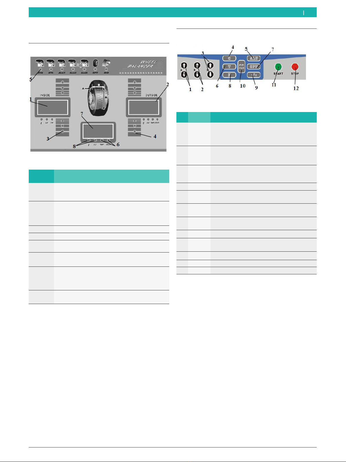
7.2 Control buttons
Fig. 15: Control buttons
No. Name Description
1 A Enter distance of wheel from MT 601 D by hand.
RArrow upwards, increase value,
RArrow downwards, reduce value.
2 B Enter rim width manually:
RArrow upwards, increase value,
RArrow downwards, reduce value.
3 D Enter rim diameter manually:
RArrow upwards, increase value,
RArrow downwards, reduce value.
4 C Calibration/reset button
5 ALU Dynamic imbalance measurement for alloy rims
(optional)
6 T Starting the self test to check the mainboard
(PCB)
7 OPT Starting the optimization process of tires and
rims
8 F Changeover between static / dynamic balancing
9 <5g Precision display of imbalance value below 5g
(0.3ounces)
10 mm/inch Changeover between millimetres/inches
11 START START button, start of measurement
12 STOP STOP button, stop measurement
!Only press key by hand. Do not press using sharp
objects.
7. Program layout
7.1 Display
Fig. 14: LED screen
No. Description
1 Left display panel A:
RDistance of rim to MT 601 D
RValue of imbalance on 1st balancing plane (inner)
2 Right display panel D:
RDiameter of rim
RValue of imbalance on 2nd balancing plane (out-
er)
3 Display of 1st balancing plane (inner)
4 Display of 2nd balancing plane (outer)
5 Display of balancing function and balancing method
6 Display of set unit
(millimetre or inch)
7 Average display panel B:
RWidth of rim
Rthe static value
RInstructions about the balancing weights
8 Display of set unit
(grams or ounces)
iAfter starting MT 601 D the screen displays the
machine code and three display windows show "8.0
5.7 14.0".

1 695 600 538 2016-07-27|
32 | Start Line MT 601 D | Program layouten
7.3 Keystroke combination for changing
between functions
Keystroke combination Description
+
Changing between grams and ounces
+
Automatic start of measurement
when closing the wheel-guard hood
+
Calibration, internal scales, A and D
values
+
Weight calibration
+
Calling up the "Attaching concealed
weights" program
iAfter the selected function has ended, the data are
retained.
7.4 Balancing programs
Symbol Description
DYN: Dynamic clip weights, on both
sides of the rim.
For the balancing of steel rims.
STA: Choose static balancing if no bal-
ancing weights are fitted to both sides
of a wheel or to the wheel(s) on a mo-
torbike.
ALU1: Balancing of light alloy rims by
attaching adhesive balance weights to
the inner and outer side of a rim.
ALU2: Attach clip-on balance weights
and adhesive balance weights to inside
of rim.
ALUS: Adhesive balance weights to any
locations on inside of rim
iWe recommend using the static balancing program
for wheel widths of less than 3.5inches (8.9cm).
For static balancing, to eliminate static imbalance,
adhesive balance weights can be attached to one
side of the rim or or adhesive balance weights can
be attached to the center of the rim. Only the di-
ameter is relevant to the imbalance result. No other
parameters are relevant.
iPress "F" to choose static balancing mode. Press
"ALU" to choose a different balancing mode.
"An LED displays the status of the balancing program.
iIn accordance with standard practice, the inside of
the tire faces the machine while the outside of the
tire faces away from the machine.
7.5 Standard program for input of rim
data
iThe form of input for rim data depends on the
choice of balancing program.
To balance a wheel successfully, please enter the fol-
lowing parameters:
¶Rim distance: Distance between wheel and
MT 601 D.
¶Rim diameter: The nominal diameter of the rim.
¶Rim width: In the standard program, to be read from
or measured on the rim.

1 695 600 538 2016-07-27|
Program layout | Start Line MT 601 D | 33 en
Automatic measurement of distance & diameter
1. Retract the rim-distance gage until the gage head is
close to the inner rim, and hold it there.
2. Whenever the warning tone sounds, return the
rim-distance gage to its starting position.
3. Read out test result from display window.
Fig. 16: Setting gage head for automatic measurement
iThe warning tone confirms the position.
"Left window shows A value (distance).
"Right window shows D value (rim diameter).
iEnter value for rim width manually.
Manual input of rim data.
1. Pull rim-distance gage onto rim.
2. Read off the scale value.
3. Using the "↑↓" keys, enter the relevant rim data for
A, B and D.
Fig. 17: Reading off scale value A (rim distance)
iThe rim width and rim diameter can also be read off
the rim.
Fig. 18: Measuring the rim diameter
iThe rim width and rim diameter can also be mea-
sured using a measuring compass.
Fig. 19: Measuring the rim width
"All data required are established and are keyed in.

1 695 600 538 2016-07-27|
34 | Start Line MT 601 D | Balancing the wheelen
7.6 Input of rim data for ALUS
iThe type of input for tire data depends on the choice
of balancing program. To balance a wheel success-
fully, please key in the following parameters.
RRim distance: Distance between wheel and machine
body.
RRim diameter: Nominal diameter of rim.
RRim width: The distance between inner and outer
balancing points.
!The balancing point depends on the choice of bal-
ancing program.
Automatic entry in ALUS balancing mode
1. Pull the rim-distance gage to inside of first adhesive
balance weight position and wait for warning tone to
confirm.
2. Pull in rim-distance gage to second inner adhesive
balance weight position and hold it there. After the
warning tone, return rim-distance gage to its starting
position.
Fig. 20: Automatic input in ALUS balancing mode
iAfter completing the process described above, the
ALUS balancing mode is selected automatically.
iThe ALUS balancing mode can also be selected
using the ALU key.
8. Balancing the wheel
WARNING – Incorrectly balanced wheels!
Risk of injury due to change in handling charac-
teristics of vehicle.
¶MT 601 D must stand on a flat surface and
must be secured.
¶Specified flange must be mounted on a
clean and grease-free flange shaft.
¶Use the specified accessories (cone, spac-
er rings).
¶Rim must contact flange accurately, re-
move any dirt.
¶Perform a reference measurement after
attaching balance weights.
8.1 Occupied area
CAUTION – Danger of injury if the wheel is
turning!
Danger of crushing of limbs when wheel is
turning for persons in the restricted area.
¶When the wheel is turning the operator
must stay in the work area.
¶There must be no persons in the restricted
area when the wheel is turning.
Fig. 21: Definition of working range
1 Area which can be occupied during the measurement
2 Area which must not be occupied during measurement

1 695 600 538 2016-07-27|
Balancing the wheel | Start Line MT 601 D | 35 en
8.2 Measuring imbalance
iThis measurement can be stopped at any time.
$Press the stop button.
$Raise wheel-guard hood.
iBefore measuring the imbalance, remove old bal-
ance weights, dirt etc. from the tire. Check to
ensure that tire is at its specified pressure. Check
locating surface of rim and distortion of installation
hole. Remove old balance weights.
1. Close the wheel-guard hood.
The dynamic mode is selected automatically.
Once the measurement is over, the value for im-
balance of the 1st balancing plane is displayed in
the left-hand display panel A and the 2nd balanc-
ing plane is displayed in the right-hand display
panel B.
2. Raise the wheel-guard hood once the measurement
process has ended.
8.3 Attaching balance weights
iAfter the balance weights have been attached, the im-
balance must be measured again to check the balance.
8.3.1 Standard procedures for clip-on weights and
adhesive weights
Attach balance weights to inside of rim, facing the ma-
chine.
1. Turn tire by hand.
The relevant indicator lights up and the warning
tone sounds once the balancing position has been
reached.
2. If a clip-on balance weight is selected, a balance
weight is fitted in the 12 o"clock position (see left-
hand display panel A for value). For adhesive balance
weights, use the automatic rim-distance gage.
Fit balance weights to outside of rim.
1. Turn tire by hand.
The relevant indicator lights up and the warning
tone sounds once the balancing position has been
reached.
2. Attach clip-on weight or adhesive balance weight in
the 12 o"clock position (see right-hand display panel D
for value).
Fig. 22: Attaching balance weights
8.3.2 ALUS balancing mode
iThe position of the adhesive balance weights is de-
termined by the automatic rim distance gage.
iThe left-hand display panel A shows the 1st bal-
ancing plane, while display panel D shows the 2nd
balancing plane.
1. Turn tire by hand.
The relevant indicator lights up and the warning
tone sounds once the imbalance point is reached.
2. Actuate pedal to hold the flange shaft.
3. Fit the required adhesive balance weights to the
head of the rim-distance gage.
4. Pull out the rim-distance gage.
5. If the left-hand window displays "――口" and if the
warning tone sounds, the point directly on the head
of the rim-distance gage is the balancing position.
iIn this way, attach weights to both balancing planes
of the wheel. The pedal light lights up while the ped-
al is being depressed to hold the flange shaft firmly.
8.3.3 Splitting the balance weights (HID program)
iFor ALUS, the balance weights can be split to con-
ceal them behind the spokes.
iAfter measurement, to split the balance weights,
please press "T+OPT". If Hide lights up, this means
that the HID function can be used.
1. Press the "T+OPT" key.
Indicator panel B displays 12o"clock.
2. Rotate tire until corresponding position on outer
side lights up. Press "ALU" key for confirmation
purposes.
3. Indicator panel B displays "-1-". Rotate tire, move
left-hand spoke with imbalance point to 12o"clokc
position on the flange shaft. To confirm, press "ALU"
key.
4. Indicator panel B displays "-2-". Rotate tire, move
left-hand spoke with imbalance point to 12o"clokc
position on the flange shaft. To confirm, press "ALU"
key.
5. Indicator panel B displays "SPD". On the outside of
the tire are two split balancing points. Correspond-
ing position on the outer side lights up, actuate
pedal to hold flange shaft in place.
6. Fit the required adhesive balance weights to the
head of the rim-distance gage.

1 695 600 538 2016-07-27|
36 | Start Line MT 601 D | Balancing the wheelen
8.4 Attaching the clip-on weights
iTo attach the clip-on weights, you need to use coun-
terweight pliers.
Fig. 23: Balance weight pliers
a. Balance hammer jaw
b. Hammerhead
c. Hook rolling groove
d. Metal shears for removal of metal
1. Find balancing position, then take off clip-on
weights.
2. Fixed the clip-on weights to rim with hammerhead.
iThe pliers end of the counterweight pliers is needed
to remove balance weights.
iCarefully remove the tire on completion of all bal-
ancing work to prevent collision impact with flange
shaft.
8.5 Attaching adhesive balance weights
!Remove all weights using adhesive balance weight
remover. To prevent damage to the rim, do not use
any other sharp objects for this job.
1. Set required number of balance weights on head of
rim-distance gage.
2. Extract rim-distance gage once window B displays
"――口" and the warning tone sounds.
3. Rotate rim-distance gage, fit it closely to the tires,
then attach weights to the rim.
4. Repeat process for the adhesive balance weight and
repeat the 2nd balancing plane.
Fig. 24: Balancing plane 1 – Attach the adhesive balance weights
Fig. 25: Balancing plane 2 – Attach the adhesive balance weights
7. Pull out the rim-distance gage. If window B displays
"――口" and if the warning tone sounds, the point
directly on the head of the rim-distance gage is the
balancing position.
8. Continue rotating tire manually to secure other bal-
ance weights behind the spokes.
Repeat steps 5 and 6.

1 695 600 538 2016-07-27|
Imbalance minimization | Start Line MT 601 D | 37 en
9. Imbalance minimization
If great wheel imbalance is measured (e.g. static im-
balance greater than 50g), it is advisable to perform
wheel matching by using the imbalance of the rim to
provide compensation for the static imbalance of the
tire (imbalance minimization). The first step involves
rotating the tire 180 degrees on the rim. Additional
minimization can then be achieved by rotating the tire
further. The matching program provides assistance with
this minimization process.
!Work as accurately as possible throughout the entire
procedure.
1. After measurement and running a balance cycle, if
the result is over 50g, press "OPT" button to call up
the function.
2. Rotate wheel to inner imbalance position, press
"OPT" button, then monitor displays "180".
3. Make double mark, on tire and rim (external side 12
o"clock position).
4. To achieve even greater precision, also make marks
on cone and shaft at 12 o"clock position.
5. Remove wheel.
6. Pull tire off rim using tire changing machine.
7. Mount tire again, but this time with mark on tire in
position 180 degrees directly opposite to the mark
on the rim.
8. Inflate tires and clamp back onto MT 601 D.
9. This time, marks on rim, cone and flange shaft
should all be at 12 o"clock position while mark on
tire should be at 6 o"clock position.
10.Switch on MT 601 D by pressing START button, or by
lowering the wheel-guard hood.
11.If MT 601 D stops rotating, turn wheel to position of
inner imbalance and only apply a mark to the rim.
Outer face at 12 o"clock position.
12.Rotate wheel to outer imbalance position, make an-
other new mark, this time only on the tire, outer side
at 12 o"clock position.
13.Remove wheel.
14.Pull tire off rim using tire changing machine.
15.Mount tire again but this time with new mark on tire
precisely aligned with new mark on rim.
"Minimization of imbalance is now finalized.
10. Adjustment
Operator error or other reasons may give rise to a
fault or malfunction. With the following adjustments,
theMT 601 D can be put back into service.
iTo set up MT 601 D, the correct parameters must
be used to assure the balancing precision of the
MT 601 D.
1. Press and hold down the C-key then, half a second
later, also press the T-key. The indicator panel dis-
plays "CAL CAL CAL", and the LED for the relevant
window flashes. If LED stops flashing, release the
keys.
2. Press A key "↑", A key "↓", and ALU key, window
now shows "re""05".
"Left and right windows now display symbols and
values.
Function Key
Change of setting/value B-key "↑""↓"
Perform next setting A-key "↑"
Adjustment Left-
hand
window
Right-
hand
window
Description
Residual imbal-
ance
re 05 Setting of residual imbal-
ance not displayed
External gage
On/Off
aut On or
Off
Adjustment of external
gage On/Off
Compensation,
internal gage
da-1 000 Adjustment of compensa-
tion value on internal gage
Compensation,
external gage
db-1 000 Adjustment of compen-
sation value for external
gage
iThe value displayed in the right-hand window is the
normal stored value.
iIn the event of data loss or replacement of the
computer PCB, the standard memory must always
be calibrated in accordance with the details on the
label inside the machine.
!If above operation is not successful, please contact
Customer Service.

1 695 600 538 2016-07-27|
38 | Start Line MT 601 D | Faultsen
11. Faults
!If the error message persists, contact customer service.
iOther possible malfunctions are primarily of a technical nature and are to be checked and if necessary recti-
fied by a qualified engineer. Please always contact the Customer Service of the dealer authorized to trade in
Beissbarth-workshop equipment.
iFor rapid assistance it is important to quote the details on the rating plate (label on MT 601 D) and the nature
of the problem when calling.
Fault Cause Remedy
No display when powering up RFuse defective
RSwitch defective
RChanging the fuse
RReplace switch
"Err1" appears on screen display Press START key and keep it held down Contact customer service
"Err2" appears on screen display RNo wheel installed in machine
RMount flange and check lead screw for back-
lash.
RWheel incorrectly installed and not secured.
RMotor belt too loose or too tight
RClamp tire and try once again
RReinstall flange
RReinstall the wheel according to 6.1
"Err3" appears on screen display Imbalance value of tire is too high To check, replace wheel and, if necessary,
perform a self check.
"Err4" appears on screen display Position sensor error Contact customer service
"Err5" appears on screen display Wheel-guard hood not closed Close wheel-guard hood
"Err7" appears on screen display Stored data missing Enter memory values and repeat self-calibra-
tion
Only 00-00 is displayed. No other
value.
RSensor head wire is broken or has a loose
contact
RStored data missing
Contact customer service
Every rotational value range has
been exceeded
RThe tire is dirty or the center contact surface
on the rim is distorted
RThe sensor head has become damp
RThe quick locking nut is not securely mount-
ed
RPower supply is too weak
RTire pressure is too low
RMachine not fixed
RReplace wheel
RReset sensor head
RUse stable power supply
RInflate tire to correct pressure.
RSecure machine to a flat concrete floor
with an expansion bolt.
Powers down within 10 seconds. RPower supply connection is loose
RFault
RCheck power connector
RRestart after powering down
The imbalance value is not correct.
Faults on left and right and very dif-
ficult to achieve imbalance of 00.
RSensor head defective
RProgram error
RRepeat self-calibration
Does not brake as soon as value is
displayed
RBrake system defective
RExternal fault
RRestart the machine
Second imbalance value exceeds 10g. RInside of rim hole not regular.
RLead screw incorrectly installed.
RTo check, replace wheel
RReinstall flange (see Chapter 5.1)
Self-calibration shows "Err8" RNo 100g self-calibration weight
RPower wire on pressure sensor is broken
RComputer PCB is defective
RPower supply PCB is defective
RAdd 100g weights
RCheck cable and connect it securely
100g is displayed as an error value RStored parameter is impaired.
RTire error value is too high
RKey in data again from label inside ma-
chine.
RTo check, replace wheel

1 695 600 538 2016-07-27|
Service | Start Line MT 601 D | 39 en
12. Service
12.1 Cleaning and Maintenance
!Before cleaning and servicing, switch off the
MT 601 D and disconnect mains plug.
!Do not use any solvent-based cleaning agents. Use
alcohol or similar cleaning agents to clean plastic
parts.
For perfect operation and to guarantee the perfor-
mance capability of MT 601 D, the following work must
be carried out at the intervals indicated:
Scope of service work
Weekly
Semi-annually
Treat and clean moving mechanical parts with spray oil
or kerosene and lubricate with engine oil or a suitable
grease.
x
Performing the check measurement x
Tab. 1: Maintenance and calibration intervals
12.2 Spare and wearing parts
The manufacturer cannot accept any liability for dam-
age arising from the use of non-genuine replacement
parts.
Designation Order number
Centering flange 1 695 602 400
Centering cone 42 - 65mm 1 695 632 500
Centering cone 54 - 80mm 1 695 652 862
Centering cone 75 - 110mm 1 695 605 600
Balance weight pliers 1 695 606 500
Manual vernier caliper 1 695 629 400
Measuring compass 1 695 602 700
Balance weight 1 695 654 377
Balance weights, calibrated 1 695 654 376
Label, electrical power supply 230 V 1 695 101 269
Label, electrical power supply 110 V 1 695 100 854
Direction of wheel rotation label 1 695 653 878
Tab. 2: Spare and wearing parts
12.3 Self-calibration
12.3.1 Self-calibration of system
1. Press and hold down the C-key then, half a second
later, also press the T-key. The indicator panel dis-
plays "CAL CAL CAL". All LEDs light up and flash. If
LED stops flashing, release the keys.
2. Press START key and start the test. When the indi-
cator panel displays "ADD" "12H", then press ALU to
confirm.
3. Whenever the indicator panel displays "100" "ADD",
then attach 100g weights to any desired positions
on outside face of wheel.
4. Start test run by pressing START key.
5. Whenever the indicator panel displays "ADD" "100",
then attach 100g weights to any desired positions
on inside face of wheel.
6. Press START key and start the test. Indicator panel
displays "END" "CAL".
7. Press START key and start the test.
8. Check result.
Description Result
Value is dis-
played
If "00""100" is displayed, ±4g deviation is
allowed.
Phase differ-
ence
All outside indicators light up, 100g
weights underneath flange shaft, ±4° error
is permitted.
"System self-calibration is now finalized.
iAfter replacement of computer PCB or pressure
sensor, the system must be recalibrated.
12.3.2 Automatic self calibration of the rim-distance
gage
1. Ensure that rim-distance gage is in starting position.
Press STOP and "<5g". The indicator panel displays
"CAL" "100".
2. Extract rim-distance gage 100mm. Press ALU key to
confirm. Indicator panel displays "CAL" "215".
3. Pull rim-distance gage out to 215mm, let head of
rim-distance gage make contact with top of inside of
tire. Press ALU key to confirm.
4. Check the result.
Description Result
The values "000" "000" "000"
are displayed
Calibration successful
"CAL" "100" is displayed Repeat self-calibration

1 695 600 538 2016-07-27|
40 | Start Line MT 601 D | Faultsen
12.4 Self-inspection
1. Press T-key. Displays light up one after the other,
from left to right. After the system test of the LEDs,
[ ][POS][ ] appears on the display screen.
2. Rotate tires until LED starts to flash. If the single
tooth on the flange shaft passes the sensor, the
display screen shows [ ][POS][ 0 ].
3. With each round, [ 0 ] appears once in the right-
hand window. When rotated in the opposite direc-
tion, the ALUS LED starts to flash.
iThe self-test program tests the position sensor and
checks that the LED is functioning normally.
12.5 Structure and setting of pressure
sensor
1. Unfasten nuts 2, 3, 4 and 5.
2. Unfasten nut1, unscrew and remove vertical rod.
3. Remove or replace pressure sensor for checking
purposes.
4. Place the measuring sensors longitudinally on the
vertical rod and transversely on the horizontal rod.
The positive terminals on both measuring sensors
should point downwards.
5. After connecting horizontal and vertical rods, screw
vertical rod into iron beam 1-1.5cm.
6. Visually check to ensure that flange shaft and ma-
chine body are perpendicular. If necessary, use nut 2
or 3 to adjust its position.
7. Tighten nut 4 by hand, then tighten for one half turn.
Then tighten nut 5 with a wrench.
8. Tighten nut 2 by hand, then tighten for one half turn.
Then tighten nut 3 with a wrench.
9. After installation, use an iron wire to short-circuit
connector on pressure sensor to discharge it.
12.6 Adjusting the belt tension
1. Remove the cover panel.
2. Unfasten motor screw, turn motor until belt tension
is OK, at which point it should be possible to press
down belt by up to 4mm.
3. Retighten motor screw then install cover.
12.7 Changing the fuse
iInstall two fuses in the power supply board and
always replace them after every malfunction.
iBefore maintenance on the pressure sensor, the ma-
chine must be powered down because the computer
PCB may otherwise burn out during removal of the
sensor head. After maintenance work on the pres-
sure sensor, perform an endurance test.
iIf the size of the clamped tire exceeds 15", bridge
pins 1 and 4 on the computer PCB. Let the machine
run continuously in extended automatic operating
mode for about 15 minutes. Then turn off the power
for about 30 minutes. Then switch the machine back
on again. Perform the endurance test 5 times or
more.
Table of contents
Other Beissbarth Wheel Balancer manuals


Popular Wheel Balancer manuals by other brands

Unitrol
Unitrol AT-26 Instruction booklet

John Bean
John Bean B 2000P Operator's manual

Snap-on Equipment
Snap-on Equipment JohnBean B2000P Series Operator's manual

Aston Global
Aston Global ADP-2000L user manual

Mondolfo Ferro
Mondolfo Ferro MT 2450 Operator's manual

Sicam
Sicam SBM V655 Original instructions

M&B Engineering
M&B Engineering WB 355 Original instruction manual

Central Machinery
Central Machinery 47211 Assembly and operation instructions

Atlas Equipment
Atlas Equipment Edge 401 unpacking instructions

Endo
Endo SBS3W instruction manual

Cormach
Cormach TOUCH MEC 1000 SONAR Technical support manual

Eagle
Eagle EB-1200 Instruction & maintenance manual