Aston Global ADP-2000L User manual

Aston Technologies Inc. www.astontechusa.com
- 1 -
Wheel Balancer User’s Manual
Model# ADP-2000L

Aston Technologies Inc. www.astontechusa.com
- 2 -
INDEX
1. INTRODUCTION ........................................................................................... 3
1.1 FUNCTION...............................................................................................................................3
1.2 PERFORMANCE AND FEATURES...........................................................................................3
1.3 TECHNICAL DATA ..................................................................................................................3
2. TRANSPORTATION AND INSTALLATION .....................................................3
2.1 WHEEL BALANCER TRANSPORTATION AND INSTALLATION .............................................3
2.2 MAIN SHAFT INSTALLATION ................................................................................................4
2.3 WARNING ..............................................................................................................................4
3. CONTROL PANEL GRAPHICS: ...................................................................... 5
4. WHEEL BALANCING OPERATION PROCESS ................................................6
4.1 ELECTRICAL CONNECTION ...................................................................................................6
4.2 WHEEL MOUNTING ..............................................................................................................6
4.2.1 Tire mounting............................................................................................................6
4.2.2 Tire mounting with special flange .....................................................................7
4.3 DIMENSION INPUT................................................................................................................7
4.4 BALANCING MODES ............................................................................................................. 8
4.5 BALANCING WHEELS............................................................................................................9
5. MAINTENANCE .......................................................................................... 10
5.1 SELF-CALIBRATION.............................................................................................................10
5.1.1 Self-calibrating with a tire balanced ............................................................... 11
5.1.2 Self-calibrating with a tire unbalanced.......................................................... 11
5.1.3 Self-calibration trouble shooting...................................................................... 11
5.3 TROUBLE SHOOTING .......................................................................................................... 13
6. STRUCTURE OF PRESSURE SENSOR AND STEPS OF ADJUSTMENT ...........15
7. ACCESSORIES............................................................................................. 16

Aston Technologies Inc. www.astontechusa.com
- 3 -
1. INTRODUCTION
Thank you for your purchasing the computer wheel balancer.
1.1 Function
Unbalance wheel results in steering wheel joggling, reduces adhesion force
of vehicle, makes the wheels jump and damages tires, shock-absorbers and
steering parts. This influences riding comfort and controlling stability and
increases oil wear, so that directly influences on vehicle’s economical
efficiency index. Balancing tire will avoid its disadvantageous effects and loss.
1.2 Performance and Features
-Automatic pneumatic brake system, manual brake position.
-It is easy to lift large sized tire with pneumatic lift.
-This machine adopts imported computer parts, it has world-advanced
electric drive system, and its life can be up to ten years.
-High strength protective cover (optional), it accords with national safety
operating procedure.
-Under the emergent circumstances, press the key STOP to stop rotating the
wheel.
-Having automatic dynamic and static balancing detecting functions.
-Having the functions that balancing three kinds of aluminum alloy rim.
-Balancing precision is up to ±1g, balancing time is very short.
-Having self-calibration and automatic diagnostic functions
1.3 Technical data
Fit for model 1200 downwards
Rim width
1.5″-20″(38.1-508mm)
Rim diameter
13″-24″(330.2-609.6mm)
Maximum wheel diameter
51"(1300mm)
Maximum wheel weight
331 lbs. (150Kg)
Air pressure
6 - 8 bar
Power supply
380V or 220V(optional)
Sound pressure level during work cycle
≤65dB
Temperature
0℃-45℃
Floor space
45"x33"x47"(3000×2500mm)
Net weight
618 lbs. (280kg)
-The Max. Weight of wheel can’t exceed 95kg when using 220v motor.
-If exceed 95kg,the motor will damage or burn.
2. Transportation and Installation
2.1 Wheel balancer transportation and Installation
-Only lift the balancer’s chassis, under any circumstances, do not lift
balancer by the main shaft. Pay attention to carry lightly.
-The machine can be installed on any firm and level ground and there is

Aston Technologies Inc. www.astontechusa.com
- 4 -
enough space around (not less than 500mm). There are screw holes on the
chassis of the machine, fix the machine into the concrete floor with expansion
bolts. And fixing it unstably will produce measurement error.
2.2 Main shaft installation
Before installing, clean up the centre hole of main shaft and connecting
piece using alcohol or gasoline, tighten the screw mandrel tightly on the main
shaft with spanner.
2.3 Warning
-Ii is recommended that regulated power supply is adopted in the unstable
power zone.
-Please read the operation manual carefully before using the machine. If in
doubt, do not use the machine and contact its manufacturer.
-Do not remove or replace parts of the machine, otherwise influence normal
work of the machine.
-Do not use strong jet of compressed air for cleaning.
-Clean the plastic panel and plastic frame with abstergent termly.
-Do not wear neck cloth and loose clothing with long fair; when the tire
rotates, operator should stand on both sides of the machine, and non-operator
cannot stand nearby.
-Do not exceed the using range of the machine during the operation process.
-All the electric appliances are installed by professional electrician.
-It is required that the machine is connected with the ground wire. When
maintaining the machine, power supply should be turned off.
-Working environment: temperature 0-50℃, in a dry and well airiness area.

Aston Technologies Inc. www.astontechusa.com
- 5 -
3. CONTROL PANEL GRAPHICS:
ⅠDisplay unbalancing value inside the
wheel edge
ⅡDisplay unbalancing value outside the
wheel edge
ⅢDisplay unbalancing position inside the
wheel edge
ⅣDisplay unbalancing position outside the wheel edge
ⅤDisplay balancing modes
ⅥIndicator for selected small sized and
large sized tire balance
A—Function key for manual input the
distance between wheel and balancer
B (L)—Function key for manual input of rim
width

Aston Technologies Inc. www.astontechusa.com
- 6 -
D—Function key for manual input of rim
diameter
Select small sized and large sized tire balance
RESET and ADJUSTMENT key
STOP key
Selected key of balancing mode
START key
<5g high accuracy balancing key (car)
<5g high accuracy balancing key (truck)
Caution: Only press the keys with hands, and do not press the keys using
clamp and any other sharp things.
4. WHEEL BALANCING OPERATION PROCESS
4.1 Electrical connection
Open the power switch, and then display the memory logo on the panel,
display “-A-”, “8.0” in a few seconds; it proves that the machine is normal.
4.2 Wheel mounting
Preparation before testing: check and clean away dust and clay on the tire,
metals and stones in the tire; check whether tire pressure accords with the
regular value; check whether the locating surface of rim and mounting hole
have deformed, and check if there are any sundries inside the tire; remove old
balancing weights.
4.2.1 Tire mounting
①Fix the screw mandrel on the
main shaft.
②Install the tire tested on the
main shaft beside the adapter.
③Select the proper cone to fit

Aston Technologies Inc. www.astontechusa.com
- 7 -
over on the main shaft.
④Tighten with lock washer nut.
4.2.2 Tire mounting with special flange
①Install the flange on the
adapter, tighten it with bolt.
②Fix the screw mandrel on
the main shaft.
③Select the proper cone to fit
over on the main shaft.
④Tighten with lock washer
nut.
Caution: 1. When fasten the large sized tire, rotate the tire 180°, fasten it
again to make sure the centre of tire positions are accurate.
2. Inner plane of special flange must accord with adapter.
4.3 Dimension input
ⅠFirst input dimension
“A”
● Measure the distance value
“A” from on the inside of rim
to the machine body with the
distance finding ruler of

Aston Technologies Inc. www.astontechusa.com
- 8 -
machine itself.
Press 〖△〗, the value increases.
Press 〖▽〗, the value reduces.
Until display the value “A” that is measured.
ⅡThen input dimension
“L” (B)
● Measure the width value
“L” (B) of rim with width
calipers.
Press 〖△〗, the value
increases.
Press 〖▽〗, the value
reduces.
Until display the value “L” (B) that is measured.
ⅢThen input dimension
“D”
● Find the nominal diameter
value “D” on the tire.
Press 〖△〗, the value
increases.
Press 〖▽〗, the value
reduces.
Until display the value
“D” that is measured.
4.4 Balancing modes
According to wheel material and rim structure, select different balancing
modes and the position of balancing weight is also placed differently.
Continuously press the key F, select balancing modes based on the state of
balancing mode indicator LEDs. When the machine is switched on every time,
the system can enter automatically dynamic balancing mode, and need not
select.
Dynamic balancing—Balance steel or
aluminum alloy rim by clipping the wheel
weights onto the rim edges.

Aston Technologies Inc. www.astontechusa.com
- 9 -
Static balancing—STATIC correction is
required for motorcycle wheels or when it is
impossible to place the weights on both
sides of the rim. The adhesive position of
wheel weights as shown in left Figure.
ALU1—Balance alloy rim by placing the
adhesive weights onto the rim shoulders.
The adhesive position of wheel weights as
shown in left Figure.
ALU2—Balance alloy rim by placing the
adhesive weights that are hidden on the
outside. The adhesive position of wheel
weights as shown in left Figure.
ALU3—Balance alloy rim by clipped the
wheel weights on the inside and placing the
adhesive weights on the outside (the position
of wheel weights on the outside as shown in
ALU2’s figure). The adhesive position of
wheel weights as shown in left Figure.
4.5 Balancing wheels
Giving an example as
follows:
1. Press startup key START,
automatic brake is displayed in
8 seconds, show in Fig.1
40 is unbalancing value inside the tire.
10 is unbalancing value outside the tire.
2. Rotate the tire slowly, when
all the inner indicator LEDs
light, shown in Fig.2, place 40g
lead block at twelve o’clock
position on the inside of rim.
Continue to rotate the tire until
a zero (0) appears in the inner
LEDs window, as Fig.3 shown.

Aston Technologies Inc. www.astontechusa.com
- 10 -
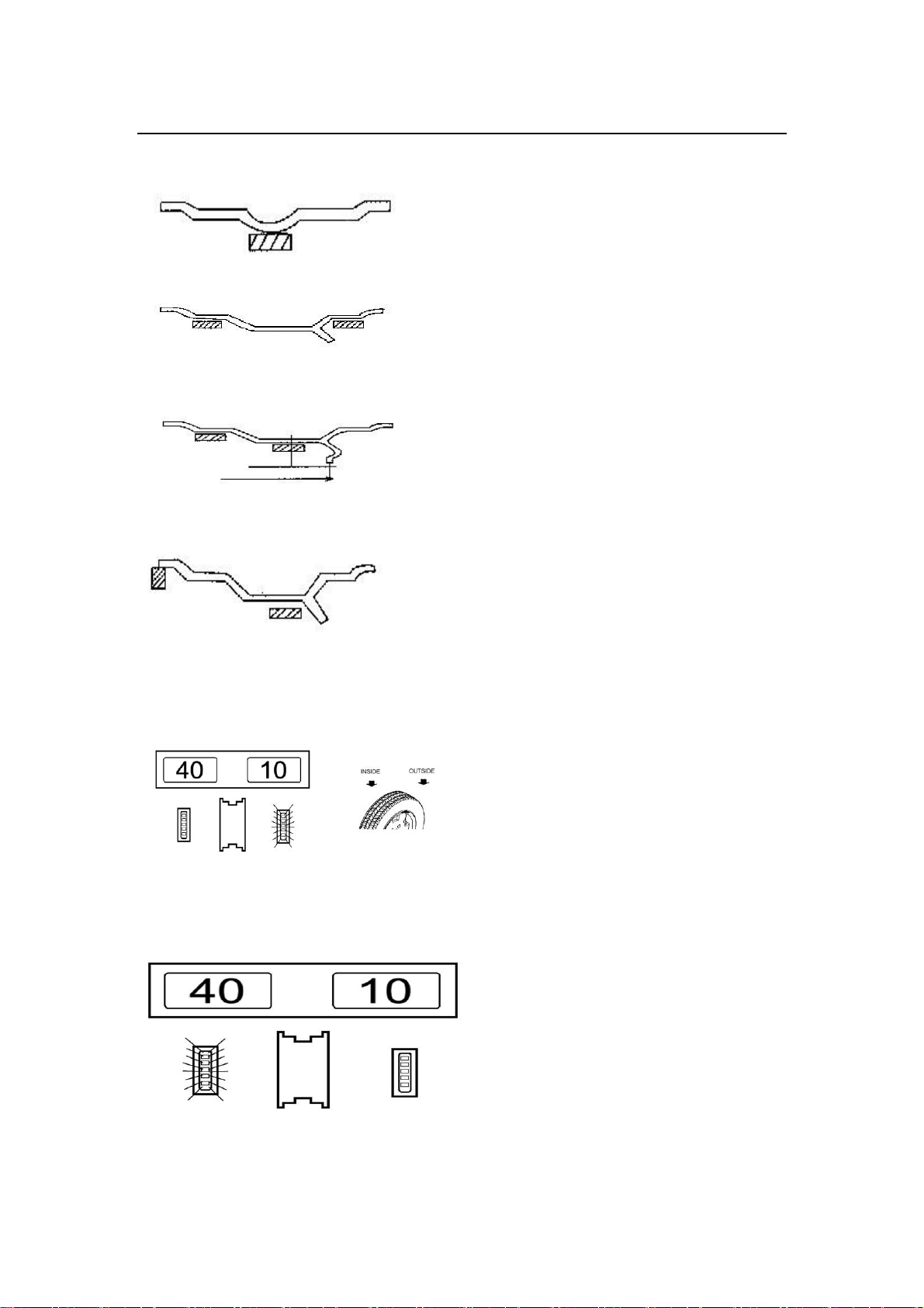
3. Rotate the tire slowly,
when all the outer indicator
LEDs light, shown in Fig.4,
place 10g lead block at twelve
o’clock position on the outside
of rim.
4. Continue to rotate the
tire again until a zero (0)
appears in the outer LEDs
window. After balancing
ends, demount the tire. If
testing the tire again, do not
turn off power supply.
Caution: 1. when the single-phase power is turned on, rotate the tire by hand
to extend the motor life.
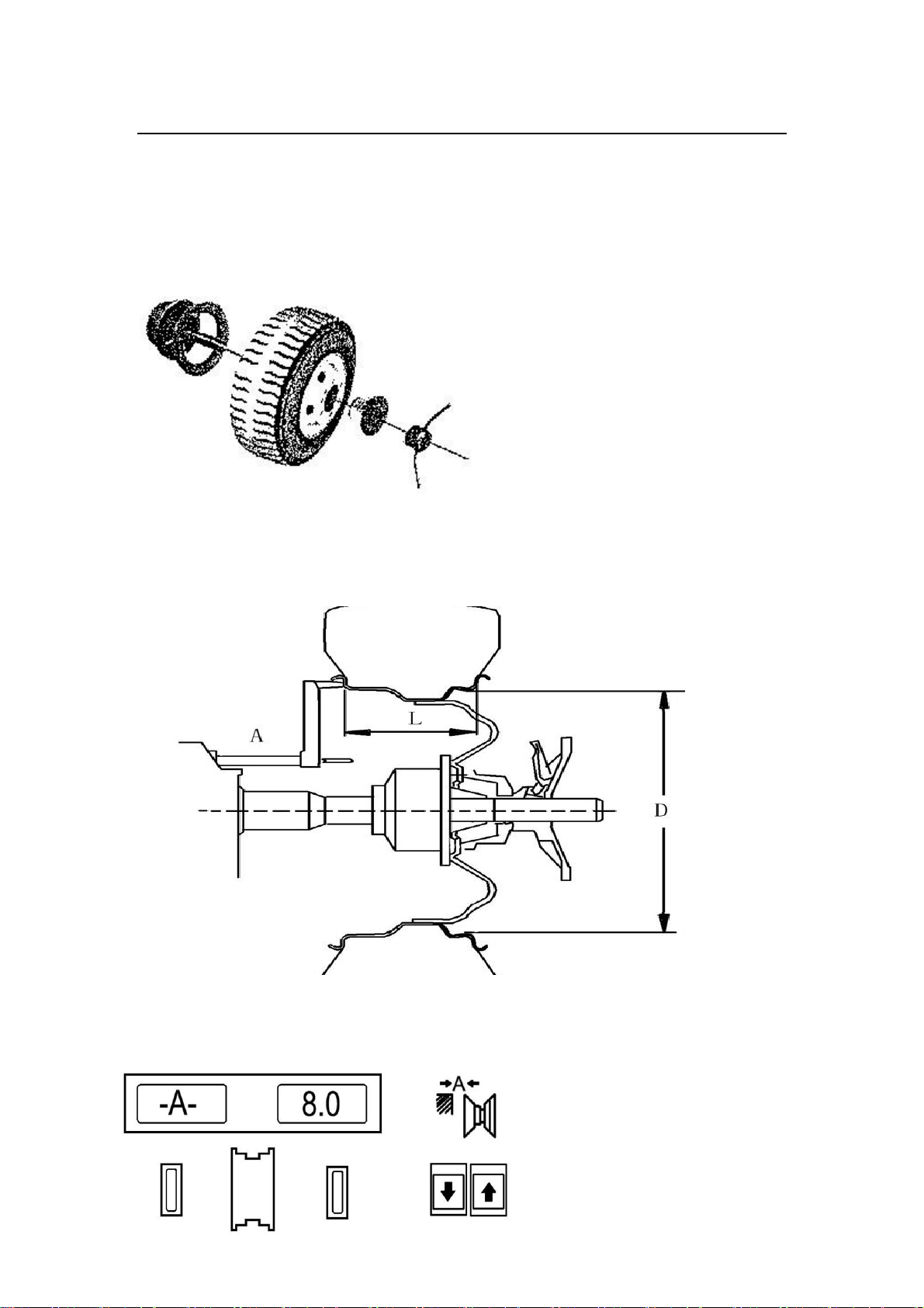
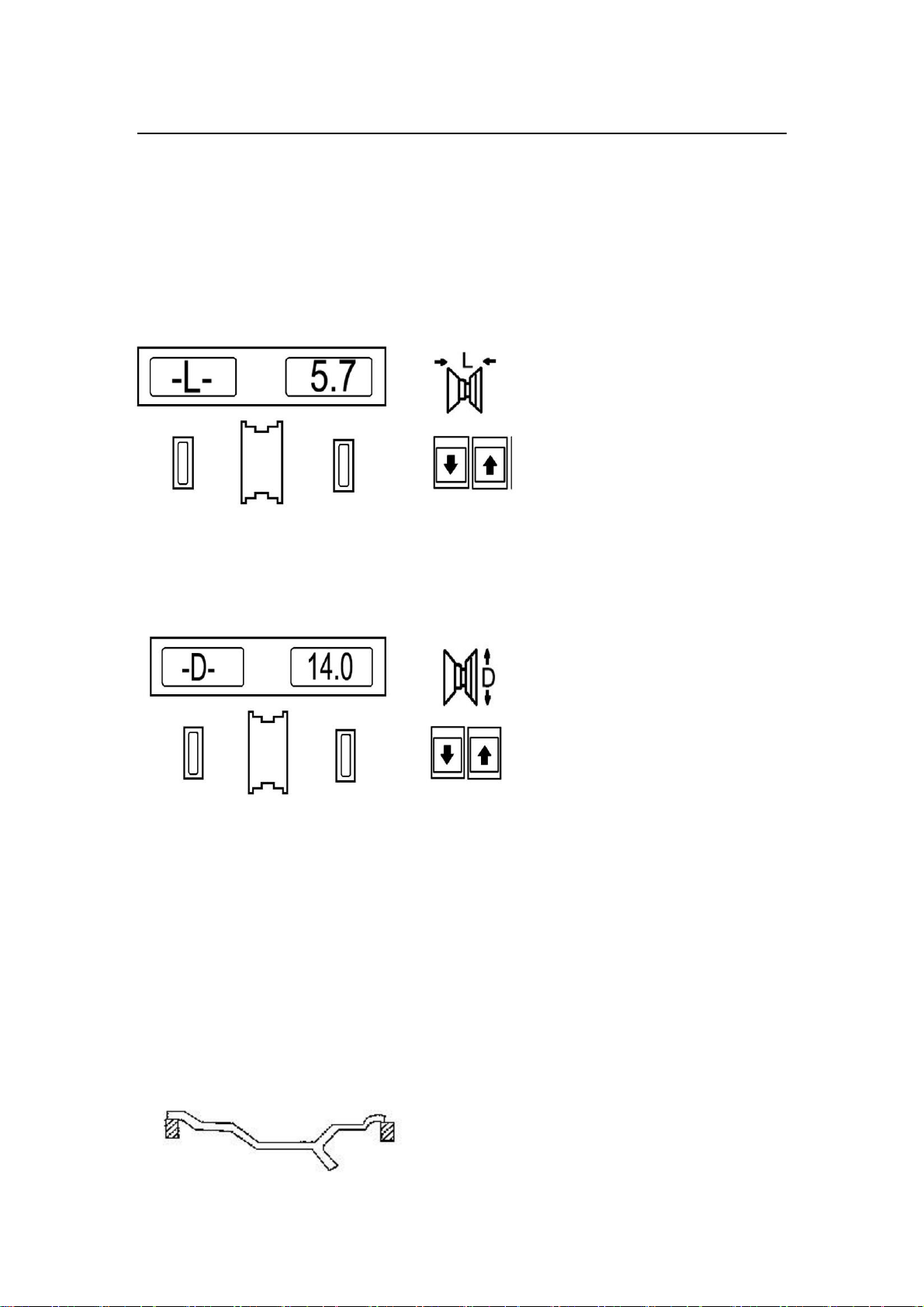
2. Check whether input dimension is wrong, press the key R to
automatically defect the value A, L, D.
3. Check whether balancing modes accord with the tire structure.
(See detailed 4.4 balancing modes)
4. Check whether the lock washer nut is tightened.
5. When dismount the tire, care is taken to carry the tire lightly and
do not impact the main shaft.
6. When balancing using balancing block with clamp, nail lightly with
balance weight on the tire edge. After balancing ends, knock it on
the floor and do not knock hard on the main shaft to avoid
damaging the sensor.
5. MAINTENANCE
5.1 Self-calibration
Self-calibration is completed in the factory. When using the machine many
years later and replace the parts of machine or doubt that balancing error is
much greater, self-calibrate over again. Select a medium-sized tire (13 inches
or 14 inches), install it on the main shaft, input the value A, L, D of this tire.
Caution: Select the better tire to self-calibrate, input the correct dimension,
or else result in calibrating inaccurately.

Aston Technologies Inc. www.astontechusa.com
- 11 -
5.1.1 Self-calibrating with a tire balanced
1. First press the keys R & START, the
display board displays “CAL”--“CAL”. Indicator
LEDs blink, release the keys after indicator
LEDs go out.
2. Then press the key START, the wheel
rotates and automatically brakes, the display
board displays “ADD”--“100”, place 100g
balancing weight at any position on the outside
of the wheel and the rim edge .
3. Then press the key START, the wheel
rotates and automatically brakes, the display
board displays “END”--“CAL”, which indicates
that self-calibration ends.
4. Press the key START again, if displaying
“00”--“100” (±4g) and outer indicator LEDs
blink, 100g balancing weight should be beneath
the main shaft (allow having ±4° error), which
indicates that self-calibration succeeds.
Judging self-calibration accuracy
1. Display numerical value accurately (allow having ±4° error).
2. Display phase position accurately (outer indicator LEDs blink,100g
balancing weight is beneath the main shaft and allow having ±4° error).
5.1.2 Self-calibrating with a tire unbalanced
1. Repeat the operation 5.1.1, 100g lead block is not beneath the main shaft,
the value displayed has error.
2. Remove 100g lead block, balance the wheel (see chapter 4.5), until a
zero (0) appears in the inner and outer LEDs window.
3. Repeat the operation 5.1.1 again, if displaying “00”--“100” (±4g) and
outer indicator LEDs blink, 100g balancing weight should be beneath the
main shaft (allow having ±4° error), which indicators that self-calibration
succeeds.
5.1.3 Self-calibration trouble shooting
Troubles
Reasons
Solutions
Display Err, -8-
1. Do not place 100g
lead block.
1. Place 100g lead block.
2. Check and connect.

Aston Technologies Inc. www.astontechusa.com
- 12 -
2. Lead wire of pressure
sensor breaks.
3. Main board goes
wrong.
3. Replace main board.
Error is much greater
after self-calibrating.
1. May be error of tire
itself is much greater.
2. Three memory
parameters confuse.
1. Replace a balanced
standard tire.
2. Adjust three memory
parameters and
self-calibrate.
The value 100g that is
displayed is inaccurate,
the position of lead
block is not beneath the
main shaft, and the tire
can be balanced with
many lead blocks.
1. The tire is not
standard or there are
sundries in the tire
2. Memory values dis
and SFA do not adjust
well.
3. The value that is
display is inaccurate.
1. Replace a standard
tire.
2.1 If the displayed value
is high, reduce the value
dis.
2.2 If the displayed
value is low, increase the
value dis.
2.3 When lead block is
away from the operator,
increase the value SFA.
2.4 When lead block is
back from the operator,
reduce the value SFA.
3. Shoot according to
trouble shooting.
If do not resolve by the above methods, please contact the manufacturer.
Caution: After replacing main board, power panel, phase position and
pressure position, self-calibration must be carried out over again. When
replace main board, setup its parameters according to original parameters, the
method sees 5.2. And self-calibrate over again after modifying.
5.2 Correcting memory data
Because incorrect operations and other reasons result in losing memory
parameters, adjust as follows and make the computer return normal work.
Correct parameter setup can guarantee its balancing precision.
Trouble: After self-calibrating, the phase position is inaccurate or the error
is too greater.
Correcting method as follows:
1. First press the keys R & START, the
display board displays “CAL”--“CAL”.
Indicator LEDs of phase position blink,
release the keys after indicator LEDs go
out.
Left Window Right Window

Aston Technologies Inc. www.astontechusa.com
- 13 -
Fig.1
2. Continuously press the keys ▽, △and F
of distance dimension A, shown in Fig.2, if
the value displayed is not correct, press
the keys △and ▽of width dimension L to
adjust.
Fig.2 Standard Memory
Correcting the degree of accuracy of value
3. Press the key △of distance dimension A,
as Fig.3 shown, which is that adjusting
static balancing parameters. When offset
data are too many, adjust to shown in
Fig.3.
Fig.3 Standard Memory
Correcting value 100g of inner of static balancing
4. Then press the key △, as Fig.4 shown,
if the value displayed is not correct,
press the keys △and ▽of width
dimension L and adjust.
Fig.4 Standard Memory
Correcting the error of degree
5. Return by pressing the key △of
distance dimension A.
6. After correcting, self-calibrate again,
see 5.1, or else correct ineffectively.
5.3 Trouble shooting
Troubles
Reasons
Solutions
Do not display after starting.
1. Check outer circuit.
2. Check whether the
switch is damaged.
3. Main board and
power panel are
damaged.
1. Check it with multi-meter.
2. Replace it.
3. Replace it.
Display after starting but do
not work and buzz, display
Err1.
Capacitor of motor did
not work.
Replace a 20UF/400V
capacitor.

Aston Technologies Inc. www.astontechusa.com
- 14 -
1. Display Err1 and do not
rotate.
2. Display Err1 and rotate.
1. Starting delay is
damaged.
2. Phase position
generator goes wrong
and main board is
damaged.
3. Power supply voltage
is much lower.
1. Replace delay or power panel.
2. Adjust photoelectric tube
shelf, replace main board.
3. Boost voltage.
Display Err2 and rotate.
1. Do not install the
wheel.
2. Only install rim but
not tire.
3. Temperature indoors
is much lower, wheel
inertia is not good.
1. Install wheel.
2. Install tire.
3. Make sure that temperature
indoors is more than 5℃.
Display Err3
Unbalance amount of
wheel is much greater.
Replace wheel or self-calibrate
over again.
Display Err4
1. If reversal, phase
position is connected
incorrectly.
2. If corotation, the
position of sensor goes
wrong.
1. Change the phase sequence of
three phases.
2. Adjust the position again or
replace it.
Display Err7
1. Memory is damaged.
2. Signal loses.
1. Replace X24C45.
2. Self-calibrate over again.
Only display invalid value
00-00.
1. Memory X24C45 is
damaged.
2. Lead wire of sensor
breaks or is loose
contact.
3. Memory value loses.
1. Replace it
2. Connect over again.
3. Input over again.
The value of changed range
every rotation is more than
5g.
1. There are sundries in
the tire.
2. Sensor is affected
with damp.
3. The machine is place
unsteadily.
4. Harmful flow disturbs
the machine such as
electric portable drill
and electric welding
machine.
1. Replace tire.
2. Drying it and adjust again.
3. Tighten fang bolts.
4. Eliminate disturb and try
again.
The value of changed range
1. There are sundries in
1. Replace tire.

Aston Technologies Inc. www.astontechusa.com
- 15 -
every rotation is more than
dozens of grams.
the tire.
2. Main board or power
panel goes wrong.
3. Sensor is placed
unsteadily.
4. Outer power voltage
is lower.
2. Replace it.
3. Check sensors and
connecting line.
4. Examine and repair or install
the manostat.
Non-stopping time is more
than 10s.
1. Power supply is loose
contact.
2. Disturb.
1. Check outer power circuitry
or replace power supply.
2. Shut down and start again.
Balancing inaccurately and do
not up to 00
1. Sensor is affected with
damp.
2. Mainboard goes
wrong.
3. Program is
disordered.
1. Adjust again, drying it and
self-calibrate.
2. Replace mainboard.
3. Self-calibrate over again.
Display value but not brake.
1. Brake system is
damaged.
2. External disturbs.
1. Replace power panel.
2. Start over again.
Twice dismounting error is
more than 10g.
1. The inner hole of
wheel is not regular.
2. Adapter is installed
improperly.
1. Replace the wheel.
2. Check the assembly surface
over again.
Self-calibration displays Err8.
1. Power panel goes
wrong.
2. Lead wire of sensor
fall back.
1. Replace wheel and try again.
2. Connect it.
Display error value of several
hundred grams
1. Three memory
parameters is
disordered.
2. Tire error is much
greater.
3. Mainboard goes
wrong.
1. Input over again.
2. Replace a tire.
3. Replace mainboard.
6. Structure of pressure sensor and steps of adjustment
During the transportation or operation process, pressure sensors are affected
with damp, which results in balancing the tire inaccurately. Then drying
pressure sensors. Operate the machine after calibrating.

Aston Technologies Inc. www.astontechusa.com
- 16 -
Steps:
1. Loosen nuts ①, ②, ③, ④.
2. Drying sensors ⑤, ⑥.
3. First tighten nut ①, and then tighten nut ②.
4. First tighten nut ③, and then tighten nut ④.
Caution: The screw mandrel cannot touch the whole edge in the board.
7. Accessories
Number
Name
Quantity
TD01
Lock washer bolt
1

Aston Technologies Inc. www.astontechusa.com
- 17 -
TD02
Calipers
1
TD03
Balancing pliers
1
TD04
Screw mandrel
1
TD05
Flange 1#
1
TD06
Flange 2#
1
TD07
Cone 1#
1
TD08
Cone 2#
1
TD09
Cone 3#
1
TD10
Cone 4#
1
TD11
Cone 5#
1
Accessories figure as follows:
WHEEL BALANCER
No.
Name
Qty.
No.
Name
Qty.

Aston Technologies Inc. www.astontechusa.com
- 18 -
101
Bearing
B5
Hexangular screw M8×30
102
Phase disc
B6
Elastic ring 8
103
Circircle
B7
Flat washer 8
104
Driven pulley
B8
Screw M4×10
105
Belt
B9
Screw M3×10
106
Mainshaft
B10
Screw with flat washer M3
×10
107
Shaft disc
B11
Nut M12
108
Big adapter
B12
Flat washer 12
109
Small adapter
B13
Belleville washer 12
110
Terminal
B14
Block washer(for shaft)
10
111
Support
B15
Flat washer 10
112
Position pick-up holder
B16
Screw M10×20
113
Complete position pick-up
board
B17
Elastic washer 10
114
Draw pole
B18
Screw M6×16
115
Threaded rod M12
B19
Key (type A)4×18
116
Washer for Belleville
washer 12
117
Sensor assembly
201
Control box body
118
Cone
202
Counterweight head
119
Cone
203
Screw M5
120
Cone
204
Adaptor carrying pin
121
Cone
205
Adaptor carrying pin
bushing
122
Cone
206
Wrest switch
123
Locknut
207
Aerodynamic button
124
Lock handle
208
Base
125
Balance hammer
209
Side panel
126
200g balance block
210
Bar plate
127
100g balance stick-up
slice
211
Brake slice
128
balance stick-up slice
212
Brake plate
129
Calipers
213
Spring
129.1
Calipers body
214
Inner valve
129.2
Connection post
215
Outer valve
130
Motor
216
Oil-water segregator
131
Small belt
217
Power line
132
Shaft mat for motor
218
Power line jacket
133
Washer for Belleville
washer 10
219
Support beam

Aston Technologies Inc. www.astontechusa.com
- 19 -
220
Panel connection board
B1
Bearing 6006 13×30×
55
221
Panel back cover
B2
Block ring(for shaft)30
222
Computer board
B3
Bearing 6005 12×25×
47
223
Insulation mat 3
B4
Block ring(for shaft)25
224
Panel scaleboard
WHEEL BALANCER)
225
panel
327
Connection line
328
filter
B20
Hexangular bolt M6×20
329
Aerodynamic control
valve
B21
Nut M6
330
Relay base
B22
Hexangular boltM6×10
B23
Screw M10×30
B40
Block ring(for shaft)
B24
Nut M10
B41
Elastic connector
B25
Hexangular bolt M4×10
B50
Screw M3×30
B26
Hexangular bolt M5×10
B51
Quick-insert joint
B27
Quick-wrest straight
terminal joint
B52
muffler
B28
Y-circle
B53
Screw M4×30
B29
Screw M8×20
B54
Elastic washer 6
B30
Block ring(for shaft)16
B55
Flat washer 6
B31
Hexangular bolt M8×20
B56
Screw M4×8
B32
Nut M4
B57
Screw M4×10
B33
Elastic washer 4
B58
Screw M3×12
B34
Flat washer 4
B35
Nut M3
350
Big plastic cover
B36
Elastic washer 3
351
Small plastic cover
B37
Flat washer 3
352
Support
B38
Screw M4×35
353
support
B39
Screw M3×30
354
Support for guard shaft
355
Connection rod
301
Gauge handle
356
Nylon washer
302
Distance gauge rod
357
Washer for Belleville
washer
303
Graduated strip
358
Connection rod bolt
304
Spring
359
Spring
305
Long bushing for gauge
360
Spring post
306
Short bushing for gauge
361
Plastic bushing
320
Power panel
362
Cam bushing

Aston Technologies Inc. www.astontechusa.com
- 20 -
321
Power main board
363
Washer for Belleville
washer
322
Aluminium spacer
323
Plastic support
B60
Screw
324
Aluminium alloy plate
325
Transformer
326
Relay
Table of contents
Other Aston Global Wheel Balancer manuals