Beissbarth MT ZERO 6 LCD Quick guide

MT ZERO 6 LCD
MT ZERO 6 LCD OEM
MT ZERO 6 LCD BMW
Radauswuchtmaschinen
Wheel Balancers
Radauswuchtmaschinen Wheel balancer
Equilibratrici per ruote
de
Betriebsanleitung
en
Operating instructions
fr
Mode d’emploi
Equilibreuses de roue
es
Manual de istrucciones
Máquinas de equilibrado de ruedas
it
Istruzioni originali
Manuale operatore
Übersetzung der
Originalbetriebsanleitung
Translation of the original
operating instructions
Traduction du manuel d'utilisation
d'origine
Traducción de las instrucciones
originales

1 695 600 968 2019-01-28| Beissbarth GmbH
68 | MT ZERO 6 LCD |
1. Symbols used 70
1.1 In the documentation 70
1.1.1 Warning notices -
Structure and meaning 70
1.1.2 Symbols in this documentation 70
1.2 On the product 70
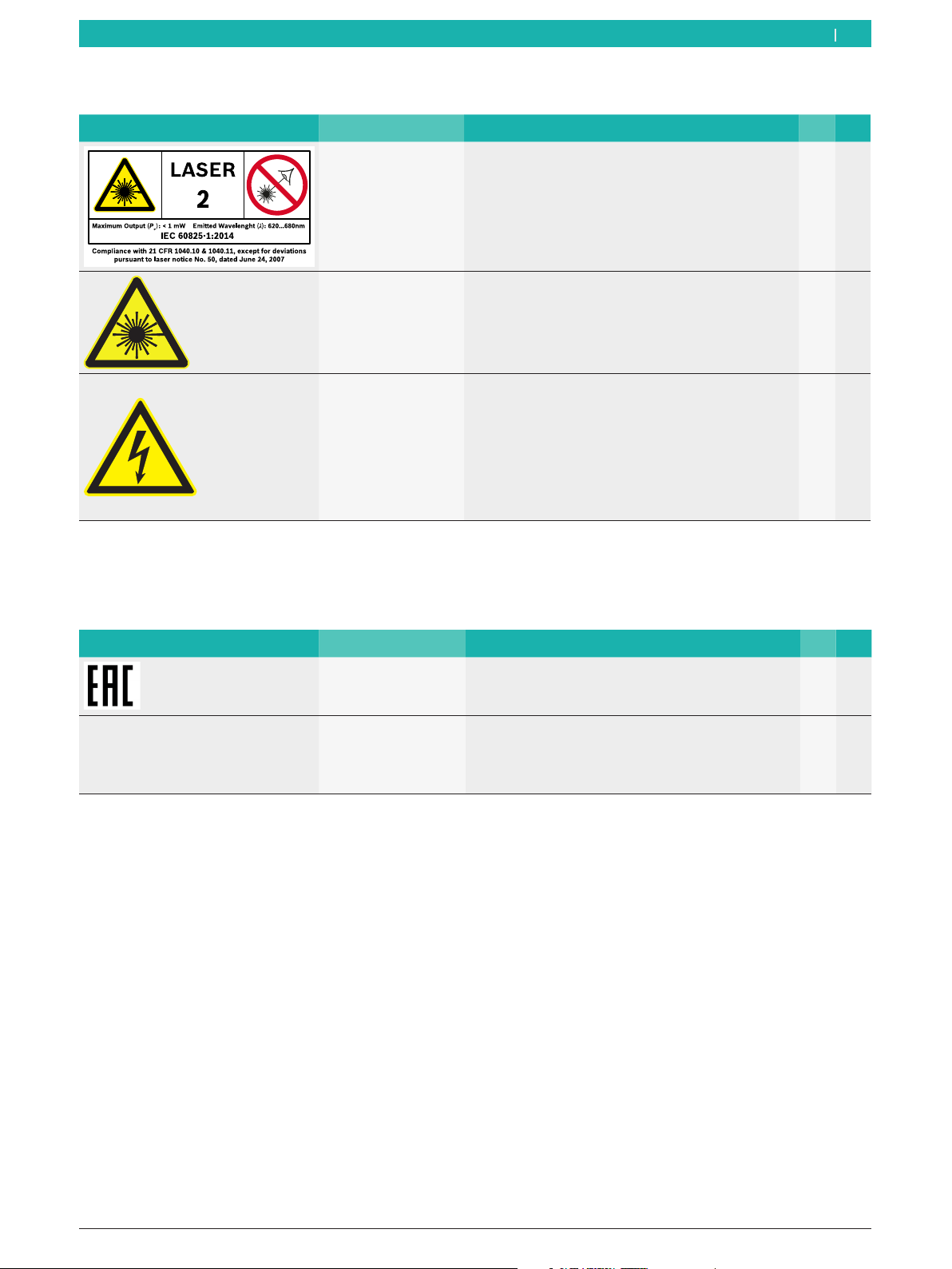
1.2.1 Safety symbols 71
1.2.2 Certification symbols 71
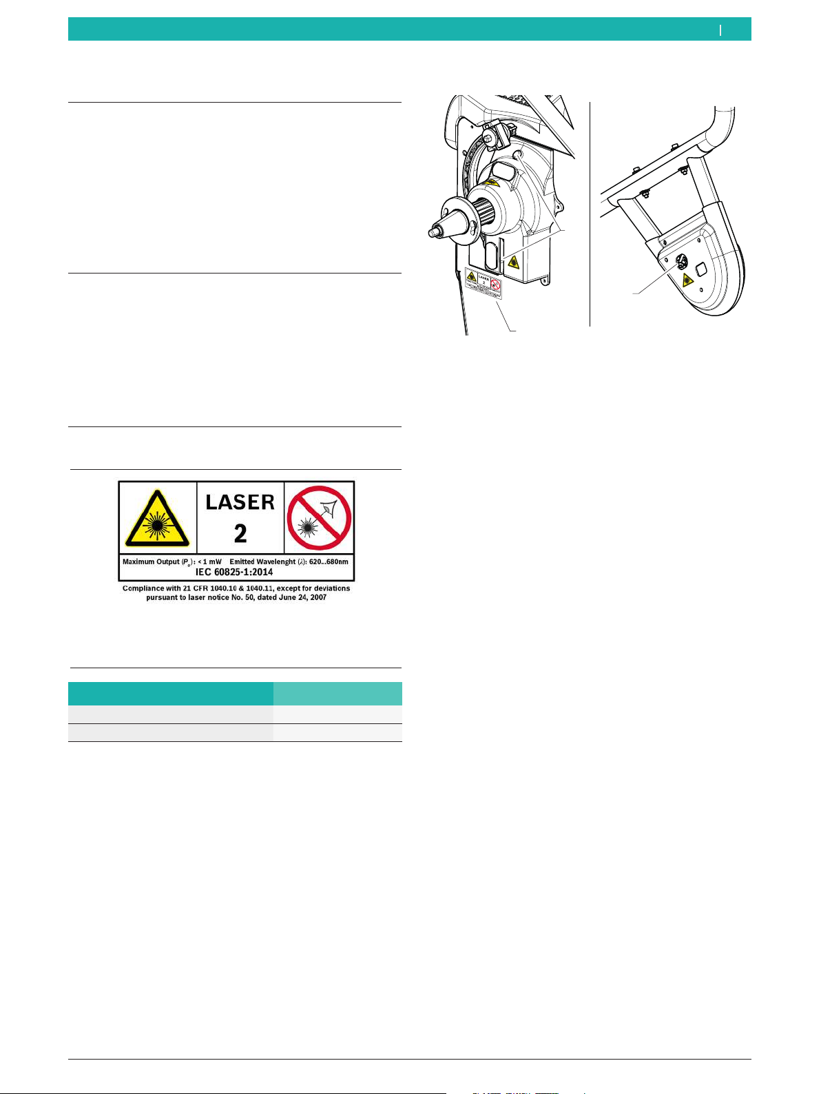
1.2.3 Symbols on the product 72
2. User information 73
2.1 Important notes 73
2.2 Safety instructions 73
3. Product description 74
3.1 Intended use 74
3.2 Prerequisites 74
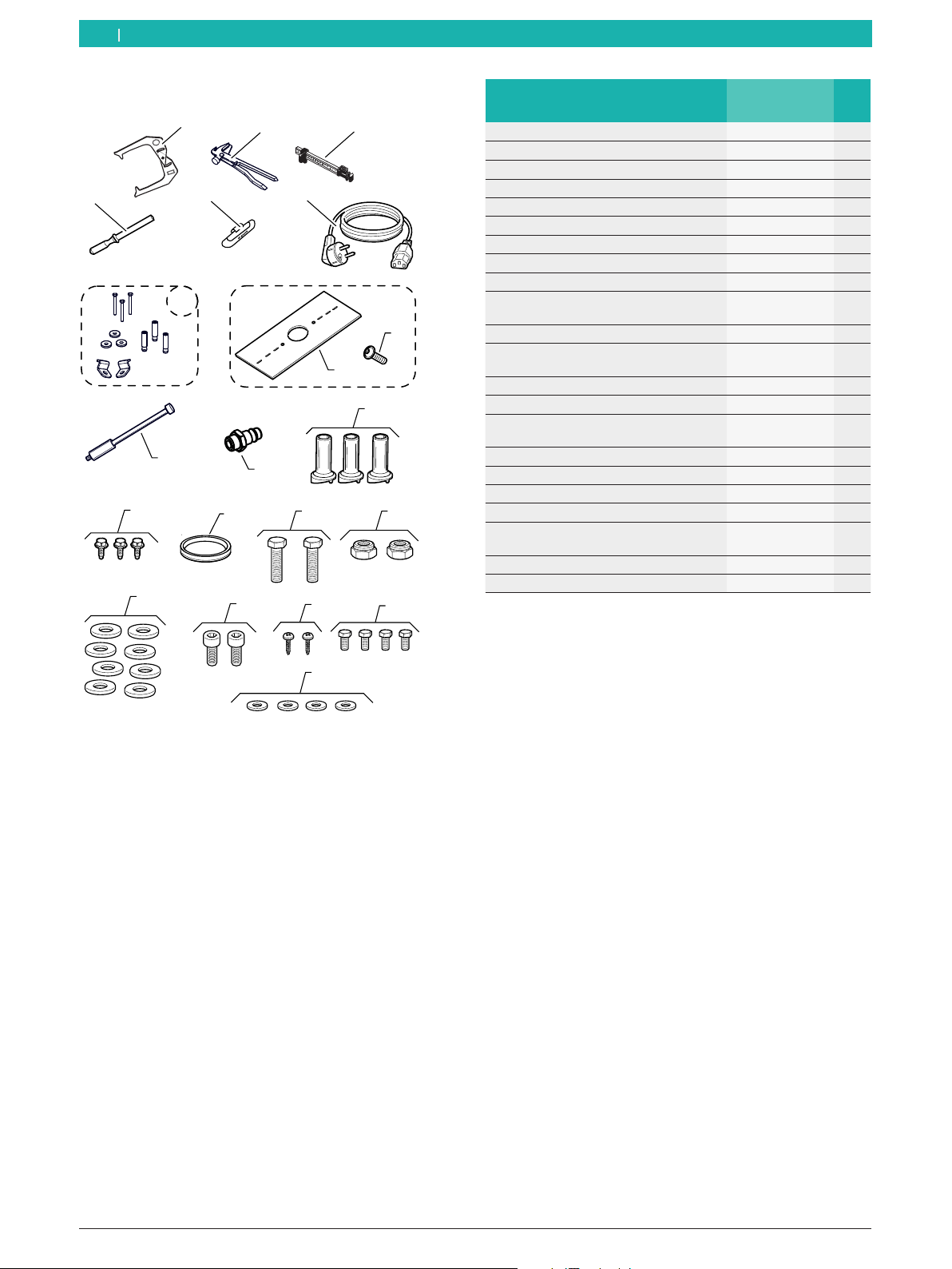
3.3 Scope of delivery 74
3.3.1 MT ZERO 6 LCD 74
3.3.2 Parts set, mechanical quick-action
clampxxx 75
3.3.3 Mechanical quick-action clamp (NA)
parts set 75
3.3.4 Parts set, pneumatic quick-action
clamp 75
3.3.5 Equipment 76
3.4 Special accessories 77
3.5 Component description 78
4. Initial commissioning 80
4.1 Unpacking 80
4.2 Transporting an handling the wheel balancing
machine 80
4.3 Floor mounting 81
4.4 Installing the wheel guard moving unit 81
4.5 Installing the support frame with sonar 83
4.6 Installing the wheel guard 84
4.7 Preparing the electrical connectors 84
4.8 Mounting the digital control panel 86
4.9 Digital control panel connections 87
4.10 Installing the clamping tool holders 88
4.11 Connecting the compressed air 88
4.12 Electrical connection 89
4.13 Ignition 89
4.14 MT ZERO 6 LCD calibration 89
5. Fitting and removing the flange 90
5.1 MT ZERO 6 LCD AWx 90
5.1.1 Removing the flange 90
5.1.2 Fitting the flange 90
5.2 MT ZERO 6 LCD AWxP 91
5.2.1 Removing the flange 91
5.2.2 Fitting the flange 91
6. Attaching and removing a wheel 92
6.1 MT ZERO 6 LCD AWx 92
6.1.1 Attaching a wheel 92
6.1.2 Removing a wheel 92
6.2 MT ZERO 6 LCD AWxP 93
6.2.1 Attaching a wheel 93
6.2.2 Removing a wheel 93
6.2.3 Wheel removal in the event of faults 93
7. Operation 94
7.1 Control keys 94
7.2 Display 94
7.2.1 Basic balancing screen 94
7.2.2 Data collection screen 95
8. Balancing the wheel 95
8.1 Important notes on balancing 95
8.2 Working range 96
8.3 Basic wheel balancing procedure 96
8.4 Selecting the type of vehicle 96
8.5 Balancing programs overview 97
8.6 Automatic balancing program selection 98
8.7 Manual balancing program selection 100
8.8 Acquiring rim data automatically 100
8.8.1 Standard, ALU1 (PAX1), ALU4, ALU5 and
all static balancing programs 100
8.8.2 ALU2 (PAX2) and ALU3 101
8.9 Manual rim data measurement 101
8.9.1 Standard, ALU1 (PAX1), ALU4, ALU5 and
all static balancing programsxxx 101
8.9.2 ALU2 (PAX2), ALU3 102
8.10 Measuring imbalance 103
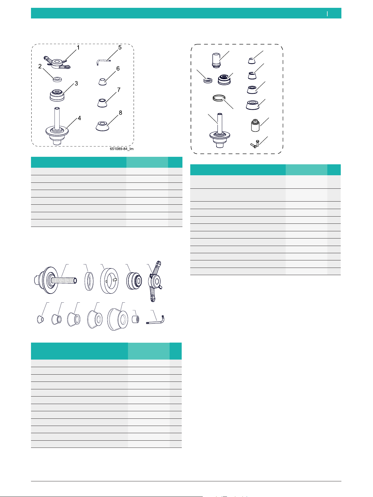
8.11 Attaching balance weights 103
8.11.1 Overview of tools for attaching the
balance weights 103
8.11.2 Positioning the wheel 104
8.11.3 Splitting balance weights (split
program) 106
en
Contents English

1 695 600 968 2019-01-28|Beissbarth GmbH
| MT ZERO 6 LCD | 69
8.12 Attaching the clip-on balance weights 108
8.13 Attaching adhesive balance weights 109
8.13.1 Overview of tools used 109
8.13.2 With the electronic rim distance
gauge 109
8.13.3 With manual vernier caliper 110
8.14 Attaching adhesive balance weights by laser
indicator 111
9. Imbalance minimization 112
10. Menu navigation 114
10.1 Menu access 114
10.2 Settings menu 114
10.3 Calibration menu 114
10.4 Statistics menu 114
10.5 Aids menu 115
10.6 Service menu 115
10.7 User Diagnostics menu 115
11. Faults 116
12. Maintenance 118
12.1 Cleaning and maintenance 118
12.2 Service intervals 118
12.3 Spare and wearing parts 118
12.4 Maintenance work 118
12.4.1 Removing condensate 118
12.4.2 Recommended oil mist lubricator
lubricants 118
12.4.3 Topping up the oil in the oil mist
lubricator 118
12.4.4 Changing the oil in the oil mist
lubricator 119
12.4.5 Setting the lubricating oil flow 119
12.5 Diagnosis 119
12.6 Calibration 119
12.6.1 Calling up the calibration menu 119
12.6.2 Calibrating the flange 119
12.6.3 Calibrate the electronic rim-distance
gauge and the sonar probe. 120
12.6.4 Calibrating by wheel and balance
weight 121
12.6.5 Reference measurement 122
12.6.6 External laser indicator calibration 123
13. Decommissioning 126
13.1 Temporary shutdown 126
13.2 Change of location 126
13.3 Disposal and scrapping 126
13.3.1 Substances hazardous to water 126
13.3.2 MT ZERO 6 LCD
and accessories 126
14. Technical data 127
14.1 MT ZERO 6 LCD 127
14.2 Temperatures 127
14.3 Working range 127
14.4 Dimensions and weights 127
en

1 695 600 968 2019-01-28| Beissbarth GmbH
70 | MT ZERO 6 LCD | Symbols used
1.2 On the product
!Observe all warning notices on products and ensure
they remain legible.
1. Symbols used
1.1 In the documentation
1.1.1 Warning notices - Structure and meaning
Warning notices warn of dangers to the user or people
in the vicinity. Warning notices also indicate the
consequences of the hazard as well as preventive action.
Warning notices have the following structure:
Warning
symbol KEY WORD – Nature and source of hazard!
Consequences of hazard in the event of
failure to observe action and information
given.
¶Hazard prevention action and information.
The key word indicates the likelihood of occurrence and
the severity of the hazard in the event of non-observance:
Key word Probability of
occurrence
Severity of danger if
instructions not observed
DANGER Immediate impending
danger
Death or severe injury
WARNING Possible impending
danger
Death or severe injury
CAUTION Possible dangerous
situation
Minor injury
1.1.2 Symbols in this documentation
Symbol Designation Explanation
!Attention Warns about possible property damage.
iInformation Practical hints and other
useful information.
1.
2.
Multi-step
operation
Instruction consisting of several steps.
eOne-step
operation
Instruction consisting of one step.
Intermediate
result
An instruction produces a visible
intermediate result.
"Final result There is a visible final result on
completion of the instruction.
en

1 695 600 968 2019-01-28|Beissbarth GmbH
Symbols used | MT ZERO 6 LCD | 71 en
1.2.1 Safety symbols
Symbols Description Definition M1P2
WARNING
There are devices fit-
ted to the product
that use laser beams!*
Indicates the type and properties of the laser
equipment used on the product and the immediate
risks of exposure.
X X
WARNING
Source of the laser
beam!*
Indicates the positions of the laser devices. X X
DANGER – live parts
when opening the
MT ZERO 6 LCD!
Risk of injury, heart failure or death from electric shock
when touching live parts (e.g. main switch, circuit
boards).
RWork on electrical systems or equipment must only
be performed by qualified electricians or trained
personnel under the guidance and supervision of an
electrician.
RDisconnect the MT ZERO 6 LCD from the mains
voltage system before opening.
X X
* Version with positioning laser only
1M = MT ZERO 6 LCD AWx
2P = MT ZERO 6 LCD AWxP
1.2.2 Certification symbols
Symbols Description Definition M1P2
EAC identification Confirms the suitability of the machine for Russia. X X
Type plate Machine model, 10-digit ID number, voltage (V),
frequency (Hz), connected load (kW), amperage (A),
max. supply pressure (kPa), degree of protection
(IP), year of manufacture, CE mark, EAC mark, serial
number of the machine, barcode.
X X
1M = MT ZERO 6 LCD AWx
2P = MT ZERO 6 LCD AWxP

1 695 600 968 2019-01-28| Beissbarth GmbH
72 | MT ZERO 6 LCD | Symbols useden
1.2.3 Symbols on the product
Symbols Description Definition M1P2
Direction of wheel
rotation
The wheel must turn in the direction of rotation
indicated (see sec. "Checking the direction of
rotation").
X X
Compressed-air
supply
After the compressed-air supply has been
disconnected, the machine parts under pressure will
move to their resting positions automatically.
X
Start/stop balancing Adhesive label on the wheel protection casing.
Indicates the direction for starting and stopping the
rotation of the flange (wheel).
X X
Intended voltage
supply
Information on the voltage set and safety warning X X
Releasing the
pneumatic flange
In case of a faulty compressed-air valve, proceed as
specified to remove the wheel.
X
STOP! Using the pedal with
single function
Adhesive label on the body above the pedal.
Indicates the functions depending on how it is used.
RPedal down:
lock shaft/wheel.
X
STOP! Using the pedal with
double function
Adhesive label on the body above the pedal.
Indicates the functions depending on how it is used.
RPedal up:
lock/release the pneumatic flange.
RPedal down:
lock shaft/wheel.
X
1M = MT ZERO 6 LCD AWx
2P = MT ZERO 6 LCD AWxP

1 695 600 968 2019-01-28|Beissbarth GmbH
User information | MT ZERO 6 LCD | 73
2. User information
2.1 Important notes
Important information on copyright, liability and
warranty provisions, as well as on equipment users
and company obligations, can be found in the separate
manual "Important notes on and safety instructions
for Beissbarth Tire Equipment". These instructions must
be carefully studied prior to start-up, connection and
operation of the MT ZERO 6 LCD and must always be
heeded.
2.2 Safety instructions
All the pertinent safety instructions can be found
in the separate manual "Important notes on and
safety instructions for Beissbarth Tire Equipment". These
instructions must be carefully studied prior to start-up,
connection and operation of the MT ZERO 6 LCD and
must always be heeded.
Safety standards for the use of the position indicator
with laser beam
LASER RADIATION
DO NOT DIRECTLY LOOK INTO THE BEAM
LASER-CLASS-2 DEVICE
Function Specification
Radiated wave length 620 nm - 680 nm
Maximum laser radiation output < 1 mW
¶The laser beam of the lighting system and the
sonar probe only serves as a position indicator for
attaching the balance weights. Any use other than
the intended use will be considered non-compliant.
The manufacturer rejects any responsibility for
improper use of the device.
Positions of the laser sources
2
1
651127-45_BM
3
Fig. 1: Positions of the laser sources
1 Main information plate position
2 Laser sources on the lighting system
3 Laser sources on the probe
Safety instructions
¶Severe eye injury from exposure of the eyes to the
laser beam (more than 0.2 seconds).
Do not look directly into the laser source and do not
expose eyes to laser beam.
¶Never direct the laser beam toward people or
animals, and do not look directly into the laser beam
or its reflection.
The laser beam may blind people, resulting in
accidents or eye injury.
¶In case the laser beam hits your eyes, immediately
close your eyes and remove your head from the laser
beam.
¶Never use laser goggles as safety goggles.
Laser goggles are used to better visually detect
the laser beam and not as protection from laser
radiation.
¶Never use laser goggles as sun glasses or behind the
wheel when driving.
Laser goggles do not offer complete protection from
UV beams and limit the perception of differences in
color.
¶Do not modify the laser equipment.
¶Switch off the wheel balancing machine before
performing any maintenance work, particularly if
work is to be performed in the immediate vicinity of
the laser sources or of areas directly exposed to the
laser beams.
¶The laser equipment must be repaired by trained
and briefed personnel using only original spare
parts. This enables the laser equipment to be used
safely.
en

1 695 600 968 2019-01-28| Beissbarth GmbH
74 | MT ZERO 6 LCD | Product description
3.2 Prerequisites
The MT ZERO 6 LCD must be installed on a flat surface
made of concrete or similar material and anchored in
position.
!An uneven or vibrating surface can lead to
inaccurate imbalance measurements.
!Any non-contiguous floor covering or deviation from
the above-mentioned safety requirements releases
the manufacturer from all liability for damage to
objects and/or personal injury.
3. Product description
3.1 Intended use
The MT ZERO 6 LCD is a wheel balancing machine
with mechanical (MT ZERO 6 LCD AWx) or pneumatic
(MT ZERO 6 LCD AWxP) wheel clamping. The
MT ZERO 6 LCD can be used to balance passenger
car, small van and motorcycle wheels with a rim
diameter between 10'' - 30'' and a rim width between
1'' - 15''1) .
The MT ZERO 6 LCD is to be used exclusively for
this purpose and solely for the range of applications
specified in these instructions. Any other purpose is not
consistent with the intended use and is therefore not
permissible.
iThe manufacturer does not accept any liability for
possible damage arising from improper use.
!1) * These dimensions refer to standard rims (A);
for rims with a special shape (B - C), special
accessories should be used.
A
B
C
Fig. 2: Rim types
¶Do not use the laser equipment in areas exposed to
explosion hazards or environments with flammable
liquids, gases or dust.
Sparks may form in the laser equipment and ignite
dust or vapors.
¶Protect the laser equipment from warmth as well as
continuous solar irradiation, fire, water and moisture.
Explosion hazard.
en
3.3 Scope of delivery
3.3.1 MT ZERO 6 LCD
651127-04_BM
41
7
2
3
5
6
Denomination Order
number
Qty.
1 Wheel guard 1 695 600 809 1
2 Wheel guard moving unit - 1
3 Mechanical quick-action clamp
parts set1)
1 695 602 400 1
3* Mechanical quick-action clamp
(NA) parts set1)
1 695 655 837 1
3** Parts set, pneumatic quick-action
clamp 1)
1 695 655 602 1
3*** Pneumatic quick-action clamp
parts set, L = 130mm1)
1 695 601 006 1
4 Support frame with sonar - 1
5 Digital control panel - 1
6 Holder for digital control panel - 1
7 Equipment - 1
Operating instructions 1 695 600 968 1
Instructions for tire service devices 1 695 000 006 1
¹)May be included in the scope of delivery depending on the version
ordered

1 695 600 968 2019-01-28|Beissbarth GmbH
Product description | MT ZERO 6 LCD | 75
3.3.2 Parts set, mechanical quick-action clampxxx
Designation Order number Qty.
1 Quick locking nut 1 695 616 200 1
2 Spacer ring 1 695 616 100 1
3 Concave socket 1 695 616 500 1
4 Basic centering flange - 1
5 Allen key 1 695 635 000 1
6 Centering cone 42 – 65mm 1 695 632 500 1
7 Centering cone 54 - 80mm 1 695 652 862 1
8 Centering cone 75 - 110mm 1 695 605 600 1
3.3.4 Parts set, pneumatic quick-action clamp
651115-17_BM
1
23
4
5
6
7
8
9
10
11
Designation Order number Qty.
1 Wheel locking sleeve
L=100mm1)
1 695 653 212 1
1* Wheel locking sleeve
L=130mm1)
1 695 600 999 1
2 Spacer ring 1 695 616 100 1
3 Concave socket 1 695 616 500 1
4 Rubber cap 1 695 624 800 1
5 Basic centering flange - 1
6 Centering cone 42 – 65mm 1 695 632 500 1
7 Centering cone 54 - 80mm 1 695 652 862 1
8 Centering cone 75 - 110mm 1 695 605 600 1
9 Centering cone 120 - 174mm 1 695 606 300 1
10 Basic centering flange 1 695 653 255 1
11 Hexagon bolt ISO 4017 MA8x30 1 695 020 514 2
¹)May be included in the scope of delivery depending on the version
ordered
en
3.3.3 Mechanical quick-action clamp (NA) parts set
651113-46_BM
1 2 3 4 5
67 8 9 10
11 12
Denomination Code for
ordering
No.
1 Basic centering flange - 1
2 Rubber cap 1 695 624 800 1
3 Spacer ring 1 695 655 316 1
4 Concave sleeve 1 695 616 500 1
5 Quick-locking nut - 1
6 Centering cone, 42–65mm 1 695 632 500 1
7 Centering cone, 60–74mm 1 695 655 841 1
8 Centering cone, 72–94mm 1 695 655 840 1
9 Centering cone, 89–132mm 1 695 653 449 1
10 Centering cone, 90–112mm 1 695 655 839 1
11 Spacer ring 1 695 654 895 1
12 Allen key 1 695 635 000 1

1 695 600 968 2019-01-28| Beissbarth GmbH
76 | MT ZERO 6 LCD | Product descriptionen
3.3.5 Equipment
8
9
7
45
32
1
11
12
13
10
15 16
17 18 19 20
21
14
6
651127-57_BM
Denomination Code for
ordering
Qty.
1 Measuring compass 1 695 602 700 1
2 Balance weight holder 1 695 606 500 1
3 Weight positioning gauge 1 695 629 400 1
4 Plastic spatula 1 695 656 585 1
5 60-g balance weight 1 695 654 377 1
6 230-V power supply cable1) 1 695 652 991 1
6* 110-V power supply cable1) 1 695 042 146 1
7 Floor mounting parts set 1 695 655 582 1
8 Calibration plate 1 695 600 938 1
9 Hex socket head cap screw
ISO7380 M8x20
1 695 042 418 1
10 Calibrating pin 1 695 656 719 1
11 Quick-release coupling –
MT ZERO 6 LCD AWxP1)
1 695 042 398 1
12 Cone holder 1 695 627 500 3
13 Self-tapping screw 6.3x16 1 695 041 397 3
14 Rubber cap –
MT ZERO 6 LCD AWx1)
1 695 624 800 1
15 Screw M8x50 ISO4017 1 695 040 041 2
16 Low nut M8 EN ISO10511 1 695 002 003 2
17 Washer M8 ISO7089 1 695 002 101 8
18 Screw M8x25 ISO4762 1 695 030 504 4
19 Self-tapping screw 4.2x16
UNI6947
1 695 000 307 4
20 Screw M5x12 ISO4017 1 695 000 410 4
21 Washer M5 ISO7089 1 695 040 163 4
¹)May be included in the scope of delivery depending on the version
ordered

1 695 600 968 2019-01-28|Beissbarth GmbH
Product description | MT ZERO 6 LCD | 77
3.4 Special accessories
Designation Code for
ordering
Cone ø 89–132 inside 40mm 1 695 653 449
Fourth centering cone Ø 120 to 174mm
1 695 606 300
Rim spacer ring 1 695 606 200
Three-arm flange for light commercial vehicles
1 695 653 420
Infinitely variable universal flange for
passenger cars
(3-4-5-hole flange)
1 695 654 043
Quick-release coupling for flange (3-4-5-hole)
kit
1 695 612 100
60-g balance weight, Zn-certified 1 695 654 376
Duo Expert centering system (3 sleeves in
carrying case, 54–78mm)
1 695 656 698
Adapter for standard rims kit 1 695 655 294
Adapter for standard rims with 4 holes 1 695 655 295
Adapter for standard rims with 5 holes 1 695 655 296
Adapter for standard rims with 6 holes 1 695 655 297
Adapter mount 1 695 655 298
DEMOBOX KIT FOR PASSENGER CARS 1 695 656 570
Quick release motorcycle wheel flange 1 695 654 039
Clamping kit for swinging arms (Ø 19mm) 1 695 654 060
Wheel lift 1 695 911 173
Positioning laser with light ring 1 695 654 994
Adapter kit for Daimler Sprinter and VW
Crafter
1 695 000 074
Centering kit for light trucks 1 695 656 783
Weight scraper 1 695 656 585
Designation Code for
ordering
Spacer plate 1 695 600 061
Large-diameter spacer plate 1 695 653 888
Rubber ring 1 695 624 800
Centering kit for GM/Opel 1 695 655 323
Centering kit for GM/Opel Expert 1 695 655 324
Three-way centering kit (42–111.5mm) 1 695 654 851
Four-way centering kit (42–111.5mm) 1 695 655 293
Centering kit for Daimler/Smart 1 695 655 326
Centering kit for BMW 1 695 656 822
Centering kit for Daimler 1 695 654 919
Centering cone for Peugeot and others
(58/65mm)
1 695 655 780
Centering cone for PSA/Renault and others
(50/60/65mm)
1 695 655 781
Centering cone for Mini Countryman and
others (72.5mm)
1 695 000 007
Centering cone for VW and others (65–
84mm)
1 695 000 073
Centering cone (50–60 / 66 / 71mm) 1 695 656 571
Centering cone for light trucks (122–174mm) 1 695 654 627
Centering cone for light trucks (88–174mm) 1 695 654 849
Spacer sleeve for off-road wheels 1 695 901 667
Printer 1 695 042 875
Shelf for printer and special accessories 1 695 656 409
Bike ECO centering kit 1 695 654 718
Clamping tool holder 1 695 107 499
en

1 695 600 968 2019-01-28| Beissbarth GmbH
78 | MT ZERO 6 LCD | Product descriptionen
3.5 Component description
12
13
1
3
2
6
14
651127-05_BM
5
7
4
8
9
10
11
15
27
26
Fig. 3: MT ZERO 6 LCD AWx
1
3
2
6
14
651127-06_BM
5
7
4
8
9
10
11
1516
17
18
26
27
Fig. 4: MT ZERO 6 LCD AWxP
19 2120 2522
23
24
651127-07_BM
Fig. 5: Accessories

1 695 600 968 2019-01-28|Beissbarth GmbH
Product description | MT ZERO 6 LCD | 79 en
Item Denomination Function
1 Wheel guard RProtecting the operator from ejected objects (e.g. dirt, water).
RStarting and stopping measurement.
2 Sonar probe RDetermines the rim width by means of the probe.
RLaser beam for indicating where to attach the clip-on balance weight on the
outside of the wheel.
3 Rim-distance gauge (electronic) RRecords rim distance and rim diameter.
RDetermines the positions for attaching the adhesive balance weights.
4 Cone of drive shaft Flange mount
5 Laser If the Easyfix® function is switched off, the position of the adhesive balance
weights is indicated by a laser beam as soon as the correct balancing position is
reached
Lighting Always switched on whenever the electronic rim-distance gauge is in use.
6 Pedal MT ZERO 6 LCD AWx
Locking the shaft/wheel
MT ZERO 6 LCD AWxP
Pedal up
Pedal down
Locking/releasing the pneumatic flange
Locking the shaft/wheel
7 Digital control panel Command interface for use of the wheel balancing machine.
8 Shelf RStorage of cones and tools.
RShelf for balance weights and accessories.
9 Mains socket Connection for power supply cable.
10 On/off switch Switching the wheel balancing machine on and off.
11 Interface card Internal interface card for connecting the measurement system.
12 Quick-locking nut MT ZERO 6 LCD AWx: centering and securing the wheel on the cone
13 Centering flange MT ZERO 6 LCD AWx: centering and securing the wheel on the cone
14 Securing cone Centering the wheel on the flange shaft.
15 Clamping tool holder Storing accessories
16 Oiler regulator filter unit for processing
the compressed air with pneumatic
connection
MT ZERO 6 LCD AWxP:
RChecking/setting the operating pressure
RRemoving dirt
RSupplying oil to compressed-air system
17 Spacer plate MT ZERO 6 LCD AWxP: centering and securing the wheel on the cone.
18 Centering flange with tie rod MT ZERO 6 LCD AWxP: centering and securing the wheel on the cone
19 Weight positioning gauge Manual measurement of the width and positioning of the adhesive balance
weights with the programs ALU2, ALU3, adhesive balance weight statics, PAX2.
20 Balance weight holder Removing the wheel weights from the rim.
21 Measuring compass Manual measurement of rim width and rim diameter.
22 Concave socket For use with quick-locking nut with outside cone attachment.
23 Spacer ring Used in combination with the quick-locking nut to secure the wheels if a cone is
used on the flange.
24 Rubber cap For protective purposes when clamping aluminum rims.
25 Plastic spatula For removing adhesive balance weights
26 USB port For updating the software.
27 Connector plate For protecting the connections used to connect the digital control panel

1 695 600 968 2019-01-28| Beissbarth GmbH
80 | MT ZERO 6 LCD | Initial commissioning
4.1 Unpacking
1. Place the packed goods near the installation
location.
iUse an appropriate fork lift or a pallet truck (with
a minimum load capacity of 400kg) to move the
packed machine. Insert the forks between the
support legs of the palette and lift the packaging.
2. Remove the strap and retaining clamps from the
pallet and the packaging carton.
3. Carefully lift off the packaging.
4. Take the standard accessories and the packaging
material out of the transport crate.
iCheck if the MT ZERO 6 LCD and the accessories
are in proper working order and that there are
no visible signs of component damage. In case of
doubt, do not commission the device and consult
customer service.
iDispose of the packaging material at an appropriate
collection site.
4.2 Transporting an handling the wheel
balancing machine
iOn delivery, the machine is fastened to the pallet.
651127-08_BM
Fig. 6: MT ZERO 6 LCD on pallet
1. Remove fastening screws.
2. Move the machine from the pallet to a suitable
position intended for installation.
iAt least 2 people are needed for this job.
!Do not lift the machine for transport by the shaft
or measurement system. That area must not be
subjected to impacts or potential damage.
651127-01_BM
Fig. 7: Places by which the machine must not be lifted for
transport
!Do not hold the machine by the plastic covers
for moving or lifting. Otherwise, there is a risk of
damage during handling or transport.
3. Carefully position the first side of the machine and
make sure that the machine is in balance and cannot
tip over.
651127-02_BM
Fig. 8: First step of setup
4. Pull out the pallet from under the machine, and
position the machine carefully.
651127-03_BM
Fig. 9: Second step of setup
en
4. Initial commissioning

1 695 600 968 2019-01-28|Beissbarth GmbH
Initial commissioning | MT ZERO 6 LCD | 81
3. The wheel balancing machine must be secured to
the ground at a minimum of 3 places with screws
and dowels.
1
2
M8x70
8,5x24x4
n°3
n°3
3
Ø8
n°3
651127-11_BM
1
2
3
1
2
3
Fig. 12: Securing the MT ZERO 6 LCD
4. Insert the dowels provided, insert the washers
in between, and fully tighten them with a torque
wrench at a tightening torque of 25Nm.
5. Set up the machine in the intended area, paying
attention to the specified safe distances.
iFor safe and ergonomic operation of the wheel
balancing machine, it is advisable to set it up at a
distance of 500mm from the nearest wall.
500 mm
500 mm
651115-08_BM
Fig. 10: Safe distances
4.3 Floor mounting
Warning – danger of tipping!
Considerable forces are involved in the wheel
balancing process.
¶Before using the machine, it is essential
to fasten it to the ground according to the
manufacturer's specifications.
1. Place the MT ZERO 6 LCD on the ground at the
intended final location. Use the bore holes in the
base of the machine for orientation.
651127-10_BM
Fig. 11: Overview of mounting holes
2. Position a power drill with a 14-mm bit, and drill
holes 65mm deep.
!We recommend cleaning the hole carefully before
inserting the dowel.
4.4 Installing the wheel guard moving
unit
iThe screws for securing the unit are already
attached to the MT ZERO 6 LCD.
1. Remove the screws for securing the cover of the
unit's casing.
2. Remove the cover.
651127-12_BM
Fig. 13: Removing the cover
en

1 695 600 968 2019-01-28| Beissbarth GmbH
82 | MT ZERO 6 LCD | Initial commissioning
3. Remove the screws from the bottom holes on the
back of the casing.
651127-42_BM
Fig. 14: Removing the bottom screws
4. Position the screws and washers on the top
holes leaving at least 5mm of space between the
structure's wall and the washer.
≥5mm
651127-13_BM
Fig. 15: Positioning the top screws
5. Anchor the protective hood of the moving unit by
aligning the top holes of the unit with the screws
previously put in place.
!Make sure not to crush the cables extending from
the bottom of the unit.
6. Push the unit down, and make sure the screws are
positioned correctly and as far in the holes as they
will go.
iThe unit must be parallel to the structure.
651127-14_BM
Fig. 16: Anchoring the moving unit
7. Position the screws and washers previously removed
on the bottom holes, but do not tighten them yet.
651127-15_BM
Fig. 17: Positioning the bottom screws
8. Tighten the top screws on the holes in the unit with
the tool.
651127-16_BM
Fig. 18: Tightening the top screws
en

1 695 600 968 2019-01-28|Beissbarth GmbH
Initial commissioning | MT ZERO 6 LCD | 83
9. Tighten the bottom screws.
!Make sure the unit is parallel to the structure.
"This concludes the installation of the moving unit of
the protective hood.
4.5 Installing the support frame with
sonar
1. Remove the support frame taking care not to
damage the cables extending from it.
iThe number of cables extending from the frame
varies depending on the machine's version. On the
wheel balancing machine with sonar functions and
laser, 2 cables are routed from the frame, while
there is just one cable on the version with sonar
only.
2. Position the support frame on the machine shaft
extending from the wheel guard moving unit.
3. Position the extending cables inside the receptacle
of the machine shaft extending from the unit.
651127-17_BM
Fig. 19: Preparation for installation
4. Connect the frame to the machine shaft. Proceed
with caution.
!Make sure not to crush the cables between the
machine shaft and the frame.
651127-18_BM
Fig. 20: Installing the support frame
5. Attach the screw set included in the scope of
delivery to the bottom hole.
iSee the figure for the direction of installation.
651127-20_BM
1
2
M8x50
Ø8
n°1
1
n°1
2
Fig. 21: Fitting the bottom screw
en

1 695 600 968 2019-01-28| Beissbarth GmbH
84 | MT ZERO 6 LCD | Initial commissioning
6. Screw the screw set included in the scope of
delivery into the threaded bore hole at the top.
iSee the figure for the direction of installation.
651127-19_BM
1
2
M8x50
Ø8
n°1
1
n°1
2
Fig. 22: Fitting the top screw
7. Fit the screw set included in the scope of delivery
for attaching the frame on the machine shaft, but do
not tighten it yet.
651127-21_BM
1
2
M8
Ø8
n°2
1
1
n°2
2
2
Fig. 23: Fitting the fastening screws
!Perform a visual inspection to make sure the
support frame is parallel to the floor of the
structure.
Fig. 24: Ensuring the parallel alignment of the support frame
iThe coupling for attaching the frame has some play.
If necessary, use it to set the correct position.
8. Tighten the screw set.
4.6 Installing the wheel guard
1. Remove the wheel guard.
2. Position the wheel guard on the frame in such a way
that the holes in the protective hood are aligned
with the holes in the frame.
3. Use the screw set included in the scope of delivery
to secure the wheel guard.
651127-22_BM
1
4,2x16
1
n°4
1
1
Fig. 25: Installing the wheel guard
4.7 Preparing the electrical connectors
iDuring this phase, the machine must not yet be
connected to the voltage supply.
1. Remove the grommet from the wheel guard moving
unit.
651127-23_BM
Fig. 26: Position of the grommet
en

1 695 600 968 2019-01-28|Beissbarth GmbH
Initial commissioning | MT ZERO 6 LCD | 85
2. Place the cables extending from the support frame
into the receptacle of the grommet, and position the
grommet as specified by the dimensions listed here.
651127-24_BM
200 mm
Fig. 27: Dimensions for positioning the grommet
3. Position the cables in the receptacle of the
grommet, and guide them towards the bottom until
they extend from the casing of the unit.
4. Position the grommet in its receptacle again.
651127-25_BM
Fig. 28: Routing the cable through the unit
5. Uninstall the plate of the interface card.
Fig. 29: Uninstalling the plate of the interface card
6. Connect the connectors shown in this figure, and
position the cables in the notches on the interface
card plate.
iInsert the washers for routing the cables into the
notches of the plate.
651127-37_BM
1 2 3
3
2
1
Fig. 30: Interface card connections
1 Micro-switch cable
2 Magnetic-sensor cable
3 Sonar cable
iIf present, connect the laser cable to the extension
inside the machine.
7. Connect the laser cable.
651127-63_BM
Fig. 31: Connecting an external laser cable
8. Position the washer for routing the cable in the
notch of the plate.
651127-64_BM
Fig. 32: Positioning the laser cable
en

1 695 600 968 2019-01-28| Beissbarth GmbH
86 | MT ZERO 6 LCD | Initial commissioning
9. Install the interface card plate on the machine.
Proceed with caution.
!Make sure not to crush the cables between the
structure and the plate.
651127-38_BM
Fig. 33: Installing the interface card plate
!To avoid damaging the cables, make sure the
cables are not excessively taut and have freedom of
movement in their notches.
10.After completion of the connections described,
install the cover of the wheel guard moving unit.
651127-27_BM
Fig. 34: Installing the cover
4.8 Mounting the digital control panel
1. Remove the holder for the digital control panel.
2. Use the screw set included in the scope of delivery
to install the mount on the back of the casing.
651127-28_BM
12
M8x25 Ø8
n°4
n°4
1
1
2
12
2
12
Fig. 35: Mounting the holder for the digital control panel
3. Remove the digital control panel.
4. Insert the cable into the holder and route it out of
the base.
651127-29_BM
Fig. 36: Cable penetration
en
This manual suits for next models
2
Table of contents
Other Beissbarth Wheel Balancer manuals