Central Machinery 47211 Parts list manual

ELECTRONIC WHEEL BALANCER
Model
47211
ASSEMBLY AND OPERATION INSTRUCTIONS
Due to continuing improvements, actual product may differ slightly from the product described herein.
3491 Mission Oaks Blvd., Camarillo, CA 93011
Visit our website at: http://www.harborfreight.com
TO PREVENT SERIOUS INJURY, READ AND UNDERSTAND
ALL WARNINGS AND INSTRUCTIONS BEFORE USE.
Copyright©2005 by Harbor Freight Tools®. All rights reserved. No portion of this
manual or any artwork contained herein may be reproduced in any shape or form
without the express written consent of Harbor Freight Tools.
For technical questions or replacement parts, please call 1-800-444-3353.
Brought to You By Augusta Flint

Page 2SKU 47211 For technical questions, please call 1-800-444-3353.
SPECIFICATIONS
Electrical Requirements 220 V / 60 Hz / Single Phase
220 Volt Electrical Power Cord Plug (Not Provided)
Product Compatibility For Most Passenger Car And Light Truck Wheels
Maximum Tire Diameter Capacity 31.5”
Maximum Tire Width Capacity 20”
Minimum/Maximum Rim Diameter Capacity 10” - 24”
Minimum/Maximum Rim Width Capacity 1.5” – 20”
Maximum Tire/Rim Weight Capacity 143 Pounds
Balancing Speed 200 RPM
Tire/Rim Balancing Modes Normal, ALU1, ALU2, ALU3, Static
Cycle Time 10 Seconds
Type of Data Entry Keypad w/L.E.D. Display Indicators
Self-Calibrating Function Semi-Automatic, User-Assisted Data Entry
(1st Set-Up, Or When Desired)
Automatic Start Feature Starts When Safety Guard Is Closed
Brake Type Automatic
Wheel Stops At Top
Weight/Length Selections Ounce And Gram / Inch And Millimeter
Balancing Accuracy .035 Ounce (1 Gram)
Overall Dimensions 52” W x 40” L x 65” H (Safety Guard Open)
52” W x 38” L x 50-1/4” H (Safety Guard Closed)
Weight 265 Pounds
Save this Manual
You will need this manual for the safety warnings and precautions, assembly, oper-
ating, inspection, maintenance and cleaning procedures, parts list and assembly diagram.
Keep your invoice with this manual. Write the invoice number on the inside of the front
cover. Keep this manual and invoice in a safe and dry place for future reference.
GENERAL SAFETY WARNINGS AND PRECAUTIONS
KEEP WORK AREA CLEAN AND DRY. Cluttered, damp, or wet work areas invite
injuries.
KEEP CHILDREN AWAY FROM WORK AREA. Do not allow children to handle
this product.
STORE IDLE EQUIPMENT. When not in use, tools and equipment should be stored
in a dry location to inhibit rust. Always lock up tools and equipment, and keep out
of reach of children.
DO NOT USE THIS PRODUCT IF UNDER THE INFLUENCE OF ALCOHOL OR
DRUGS. Read warning labels on prescriptions to determine if your judgement or
reflexes are impaired while taking drugs. If there is any doubt, do not attempt to
use this product.
1.
2.
3.
4.
Brought to You By Augusta Flint

Page 3SKU 47211 For technical questions, please call 1-800-444-3353.
USE EYE PROTECTION. Wear ANSI approved safety impact eyeglasses when
using this product. ANSI approved safety impact eyeglasses are available from
Harbor Freight Tools.
DRESS SAFELY. Do not wear loose clothing or jewelry, as they can become
caught in moving parts. Wear a protective hair covering to prevent long hair from
becoming caught in moving parts. If wearing a long-sleeve shirt, roll sleeves up
above elbows.
DO NOT OVERREACH. Keep proper footing and balance at all times to prevent
tripping, falling, back injury, etcetera.
INDUSTRIAL APPLICATIONS MUST FOLLOW OSHA REQUIREMENT.
STAY ALERT. Watch what you are doing at all times. Use common sense. Do not
use this product when you are tired or distracted from the job at hand.
CHECK FOR DAMAGED PARTS. Before using this product, carefully check that
it will operate properly and perform its intended function. Check for damaged parts
and any other conditions that may affect the operation of this product. Replace or
repair damaged or worn parts immediately.
REPLACEMENT PARTS AND ACCESSORIES: When servicing, use only identical
replacement parts. Only use accessories intended for use with this product. Ap-
proved accessories are available from Harbor Freight Tools.
MAINTAIN THIS PRODUCT WITH CARE. Keep this product clean and dry for
better and safer performance.
MAINTENANCE: For your safety, service and maintenance should be performed
regularly by a qualified technician.
USE THE RIGHT TOOL FOR THE JOB. Do not attempt to force a small tool or
attachment to do the work of a larger industrial tool. There are certain applications
for which this tool was designed. It will do the job better and more safely at the
rate for which it was intended. Do not modify this tool, and do not use this tool for
a purpose for which it was not intended.
WARNING: The warnings, precautions, and instructions discussed in this manual
cannot cover all possible conditions and situations that may occur. The operator
must understand that common sense and caution are factors, which cannot be built
into this product, but must be supplied by the operator.
SPECIFIC PRODUCT WARNINGS AND PRECAUTIONS
MAKE SURE THIS MACHINE IS USED ON A DRY, FLAT, LEVEL, OIL/GREASE
FREE, CONCRETE SURFACE capable of supporting the weight of the Wheel Bal-
ancer, the tire being balanced, and any additional tools and equipment.
5.
6.
7.
8.
9.
10.
11.
12.
13.
14.
15.
1.
Brought to You By Augusta Flint

Page 4SKU 47211 For technical questions, please call 1-800-444-3353.
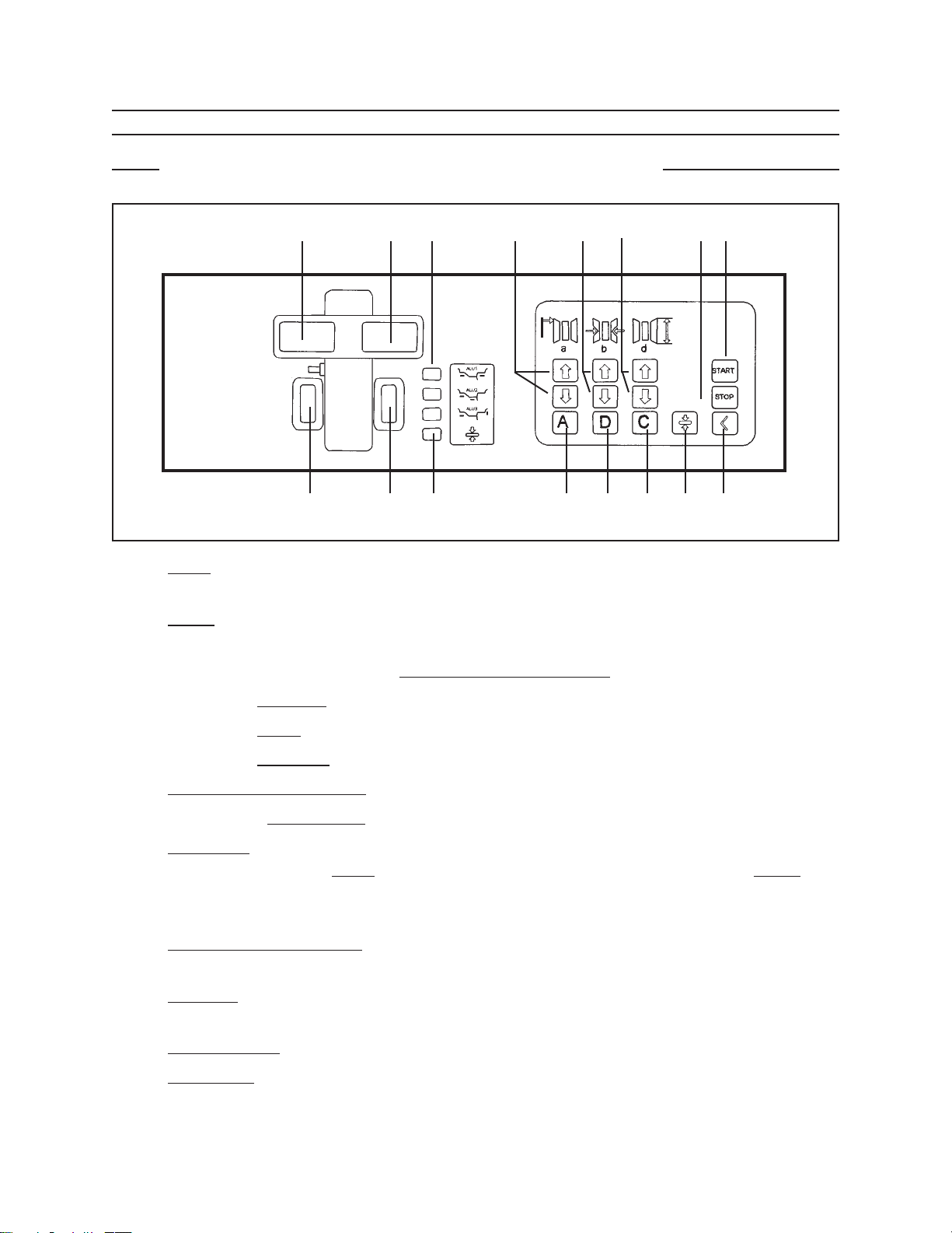
BEFORE EACH USE, ALWAYS EXAMINETHEWHEEL BALANCER FOR STRUC-
TURAL CRACKS AND BENDS, DAMAGE TO THE SAFETY GUARD (504) AND
ELECTRICAL WIRING, AND ANY OTHER CONDITION THAT MAY AFFECT THE
SAFE OPERATION OF THE MACHINE. Do not use the Wheel Balancer even if
minor damage appears. (See Figure E.)
MAINTAIN A SAFEWORKING ENVIRONMENT. Keep the work area well lit. Make
sure there is adequate surrounding workspace. Always keep the work area free of
obstructions, grease, oil, trash, and other debris. Do not use the Wheel Balancer
in a damp or wet location. Do not use the Wheel Balancer in areas near flammable
chemicals, dusts, and vapors.
THIS WHEEL BALANCER IS DESIGNED FOR USE WITH MOST PASSENGER
CAR AND LIGHT DUTYTRUCKWHEELS. Do not attempt to exceed this machine’s
maximum wheel diameter capacity of 31-1/2” or the maximum wheel width capacity
of 20”.
PRIOR TO BEGINNING A JOB, MAKE SURE THE SAFETY GUARD (504) IS IN
THE PROPER LOWERED POSITION. DO NOT RAISE THE SAFETY GUARD
UNTIL THE SPINNING WHEEL COMES TO A COMPLETE STOP.
(See Figure E.)
ALWAYS KEEP HANDS, FINGERS, AND FEET AWAY FROMTHE MOVING PARTS
OF THE WHEEL BALANCER WHILE THE MACHINE IS IN USE. Remain clear of
the spinning wheel while it is being balanced.
NEVER LEAVE THE WHEEL BALANCER UNATTENDED WHEN IT IS RUNNING.
After completing a wheel balancing job, always turn the Power Switch (523) to its
“OFF” position, and wait until the machine comes to a complete stop before leav-
ing. (See Figure E.)
MAKE SURETO READ AND UNDERSTAND ALL INSTRUCTIONS AND SAFETY
PRECAUTIONS AS OUTLINED IN THE MANUFACTURER’S MANUAL FOR THE
WHEEL YOU ARE BALANCING, AND THE VEHICLE THE WHEEL IS TO BE
USED ON.
BEFORE TURNING THE MACHINE ON, MAKE SURE TOOLS, TOOL TRAYS,
WHEELWEIGHTS, AND ALL OTHER PARTS AND EQUIPMENT ARE REMOVED
FROMTHE IMMEDIATELY VICINITY OF THE MOUNTED WHEEL THAT ISTO BE
BALANCED.
NEVER STAND OR ALLOW AN OBSERVER TO STAND IN LINE WITH THE
SPINNING WHEEL.
THE WHEEL BALANCER DOES NOT COME EQUIPPED WITH AN ELECTRI-
CAL POWER PLUG. Prior to using, this machine requires the attachment of a
grounded, 3-prong, 220 volt, Power Plug to its Power Cord (519). For your safety,
only a qualified, certified electrician should attach the Power Plug onto the Power
2.
3.
4.
5.
6.
7.
8.
9.
10.
11.
Brought to You By Augusta Flint

Page 5SKU 47211 For technical questions, please call 1-800-444-3353.
Cord. Never remove the grounding prong or modify the Plug in any way. Do not
use adapter plugs with the Power Plug. To comply with the National Electric Code,
and to provide additional protection from the risk of electrical shock, the Power Plug
should only be connected to a 220 Volt, 3-hole electrical outlet that is protected by
a Ground Fault Circuit Interrupter (GFCI). (See Assy. Diagram E.)
RECOMMENDED MINIMUM WIRE GAUGE FOR EXTENSION CORDS*
(120 OR 240 VOLT)
NAMEPLATE
AMPERES
(at full load)
EXTENSION CORD LENGTH
25 Feet 50 Feet 75 Feet 100 Feet 150 Feet
0 – 2.0 18 18 18 18 16
2.1 – 3.4 18 18 18 16 14
3.5 – 5.0 18 18 16 14 12
5.1 – 7.0 18 16 14 12 12
7.1 – 12.0 18 14 12 10 -
12.1 – 16.0 14 12 10 - -
16.1 – 20.0 12 10 - - -
TABLE A * Based on limiting the line voltage drop to five volts at 150% of the rated amperes.
IF AN EXTENSION CORD (not provided) IS USED, MAKE SURE TO USE ONLY
UL APPROVED CORDS HAVING THE CORRECT GAUGE AND LENGTH.
(See Table A.)
ALWAYS UNPLUG THE WHEEL BALANCER FROM ITS ELECTRICAL SUPPLY
SOURCE BEFORE PERFORMING ANY INSPECTION, MAINTENANCE, OR
CLEANING PROCEDURES.
WARNING: This product contains or produces a chemical known to the State of
California to cause cancer and birth defects (or other reproductive harm).
(California Health & Safety Code § 25249.5 et seq.)
WARNING: People with pacemakers should consult their physician(s) before using
this product. Operation of electrical equipment in close proximity to a heart pace-
maker could cause interference or failure of the pacemaker.
UNPACKING
When unpacking, check to make sure all the parts shown on the Parts Lists are
included. If any parts are missing or broken, please call Harbor Freight Tools at the number
shown on the cover of this manual as soon as possible.
12.
13.
14.
15.
Brought to You By Augusta Flint

Page 6SKU 47211 For technical questions, please call 1-800-444-3353.
INSTALLATION AND ASSEMBLY INSTRUCTIONS
Note: For additional references to the parts listed below, refer to the Assembly Diagrams
near the end of this manual.
To Determine The Proper Location For The Wheel Balancer:
WARNING: Make sure this machine is used on a dry, oil/grease free, flat, level,
CONCRETE surface capable of supporting the weight of the Wheel Balancer, the
wheel being balanced, and any additional tools and equipment.
The Wheel Balancer is designed for indoors use only. Do not install or use the
Wheel Balancer outdoors, or in damp or wet locations.
Make sure to check the desired location for possible obstructions such as a low ceil-
ing, overhead lines, adequate working area, access ways, exits, etcetera. The Wheel
Balancer should be located in an area free of flammable materials and liquids.
To Mount The Wheel Balancer On A Floor Surface:
With assistance, and with the use of a lifting device, stand the Wheel Balancer in its
upright position in the desired work location. Use the three, 1/2” machine mounting
holes located at the base of the Body (501) as a template to mark the points where
three floor anchor holes will be drilled in the floor surface. Then, temporarily remove
the Wheel Balancer. (See Figure B, next page, and Assy. Diagram D.)
Where previously marked on the concrete floor surface, drill three 1/2” diameter,
minimum 4” deep, anchor holes. NOTE: Be sure to blow out the cement dust from
the drilled holes.
Move the Wheel Balancer back to the desired location, and align the three machine
mounting holes at the base of the Body (501) with the three previously drilled floor
anchor holes. If necessary, level the Wheel Balancer by inserting steel shims be-
tween the base of the machine and the concrete floor surface. Do not exceed more
than 1/2” thickness of shims.
1.
2.
3.
1.
2.
3.
Brought to You By Augusta Flint

Page 7SKU 47211 For technical questions, please call 1-800-444-3353.
1/2” ANCHOR BOLT, WASHER, NUT
(NOT PROVIDED)
FRONT
VIEW
TOP
VIEW
1/2” MACHINE
MOUNTING HOLE
CONCRETE
FLOOR SURFACE
FLOOR
ANCHOR HOLE
FIGURE B
Secure the Wheel Balancer to the concrete floor surface, using three 1/2” diameter
concrete anchor bolts of appropriate length, three washers, and three nuts (not
provided). (See Figure B.)
To Attach The Safety Guard To The Wheel Balancer:
Slide the Sheath (106) onto the Shaft (108). Align the mounting hole of the Sheath
with the rear mounting hole of the Shaft. Then, secure the Sheath to the Shaft,
using the Screw (107). (See Assy. Diagram B.)
Slide the mounting hole of the Safety Guard (504) onto the Shaft (108). Make sure
to position the mounting hole of the Safety Guard against the pre-attached Sheath
(106). (See Assy. Diagram B.)
Slide the Plastic Lip (104) onto the exposed end of the Shaft (108). Align the mount-
ing hole of the Plastic Lip with the remaining mounting hole of the Shaft. Then,
secure the Plastic Lip to the Shaft, using the Screw (105). Attaching the Safety
Guard (504) to the machine is now completed. (See Assy. Diagram B.)
The Safety Guard (504) must always be in place while the Wheel Balancer is in
operation.
4.
1.
2.
3.
4.
Brought to You By Augusta Flint

Page 8SKU 47211 For technical questions, please call 1-800-444-3353.
CONTROL BOARD FEATURES
Note: For additional references to the parts listed below, refer to the Assembly Diagrams
near the end of this manual.
A B C D E F H G
P O N M L K J I
FIGURE C
Inner side UNBALANCE VALUE digital display. Indicates what size weight to attach
on inside edge of wheel rim.
Outer side UNBALANCE VALUE digital display. Indicates what size weight to attach
on outside edge of wheel rim.
Display showing the type of ALU balancing procedure selected.
Wheel rim distance calibration key.
Wheel rim width calibration key.
Wheel rim diameter calibration key.
START measuring cycle key.
Emergency STOP cycle key.
Threshold key. Use when the machine is at a standstill (not spinning), and only when
the readings on the Inner side UNBALANCE VALUE digital display and Outer side
UNBALANCE VALUE digital display must indicate an unbalance reading of below
0.2 ounces (5 grams).
Unbalance optimization key. Allows you to reduce the amount of weight to add to
the wheel rim in order for it to be balanced.
Numeric key. Allows you to display all readings in ounces/inches, or grams/mm.
Self-calibrating.
Recalculation key. Allows you to cancel some or all previously entered values.
Correcting key. Allows you to select the type of value correction to be made (i.e.,
distance, width, diameter).
A.
B.
C.
D.
E.
F.
G.
H.
I.
J.
K.
L.
M.
Brought to You By Augusta Flint

Page 9SKU 47211 For technical questions, please call 1-800-444-3353.
Unbalance optimization display. Indicates the STATIC balancing procedure has
been selected.
Outer side UNBALANCE POSITION display. Indicates the weight must be attached
at the top of the wheel rim when all LED’s are illuminated.
Inner side UNBALANCE POSITION display. Indicates the weight must be attached
at the top of the wheel rim when all LED’s are illuminated.
FIGURE D
N.
O.
P.
Brought to You By Augusta Flint

Page 10SKU 47211 For technical questions, please call 1-800-444-3353.
GENERAL OPERATING INSTRUCTIONS
Note: For additional references to the parts listed below, refer to the Assembly Diagrams
near the end of this manual.
To Mount A Wheel Onto The Balancer:
Connect the Plug (not provided) of the Power Cord (519) into a properly grounded,
3-hole, 220 volt, electrical receptacle. (See Assy. Diagram E.)
SAFETY GUARD
(504)
POWER SWITCH
(523)
RIM DISTANCE
POINTER
(202)
FLANGE (23)
TRANSMISSION SHAFT (24)
CONE (18)
THUMB LOCK
ADJUSTABLE
NUT
(16)
INNER
SIDE
OUTER
SIDE
WHEEL
FIGURE E
Raise the Safety Guard (504) to its full “UP” position.
(See Figure E, and Assy. Diagram E.)
Insert the center hole of the wheel rim (not provided) onto the Transmission Shaft
(24). Make sure to position the inner side of the wheel rim against the Flange (23).
(See Figure E, and Assy. Diagram A.)
1.
2.
3.
Brought to You By Augusta Flint

Page 11SKU 47211 For technical questions, please call 1-800-444-3353.
Select the proper size Cone diameter (18) that will ensure the wheel rim is tightly
secured (no wheel wobble) to the Transmission Shaft. Insert the Cone onto the
Transmission Shaft and partially through the center hole of the wheel rim.
(See Figure E, and Assy. Diagram A.)
Hold the Adjustable Nut (16) with both hands. While doing so, use your thumb to
move the Thumb Lock on the Adjustable Nut to the right. While holding the Thumb
Lock in position, slide the Adjustable Nut onto the Transmission Shaft (24) and firmly
against the Cone (18). Then, release the Thumb Lock and allow it to lock the wheel
rim in place on the Transmission Shaft. (See Figure E, and Assy. Diagram A.)
To Make Wheel Measurements:
NOTE: Though the Wheel Balancer may be programmed to input numeric values
and display numeric values in ounces/inches or grams/mm, this manual will use
ounces/inches numeric values for ease of instruction. For instructions on how to
select and change numeric values in ounces/inches or grams/millimeters.
(See Figure D.)
Remove all old weights, dirt, and debris from the wheel that is to be measured and
balanced.
Turn the Power Switch (523) to its “ON” position.
(See Figure E, and Assy. Diagram E.)
RIM DISTANCE
POINTER
(202)
TIRE
RIM DISTANCE
GAUGE (208)
WHEEL
RIM FIGURE F
Measure the wheel rim distance (reading a) by pulling the Rim Distance Pointer
(202) horizontally to the right until its tip touches the top/inner edge of the wheel
rim. (See Figures E, F, and Assy. Diagram B.)
4.
5.
1.
2.
3.
4.
Brought to You By Augusta Flint

Page 12SKU 47211 For technical questions, please call 1-800-444-3353.
Attached to the Rim Distance Pointer (202) is the Rim Distance Gauge (208) which
indicates the numeric value (in inches or millimeters) to enter for the wheel rim
distance. (See Figure F, and Assy. Diagram B.)
Make sure to move the Rim Distance Pointer (202) away from the wheel rim and
back to its original position. Then, enter the distance numeric value that was shown
on the Rim Distance Gauge (208) by following the instructions in Figure D.
RIM
CALIPER
WEIGHT
PLIERS
FIGURE G
Wheel rim manufacturers usually indicate the wheel rim width (reading b) by
stamping the width numeric value into the top/outer edge of the wheel rim. Locate
the manufacturer’s stamped width numeric value on the wheel rim. NOTE: If the
manufacturer does not indicate the width, use the Rim Caliper that is provided
with the Wheel Balancer. To do so, position one tip of the Rim Caliper against the
top/inner edge of the wheel rim. Place the other tip of the Rim Caliper against the
top/outer edge of the wheel rim. The gauge on the Rim Caliper will indicate the
proper width. (See Figure F, and Figure G.)
Enter the width numeric value shown on the wheel rim (or Rim Caliper) by following
the instructions in Figure D.
Tire manufacturers usually indicate the tire diameter (reading d) by stamping the
diameter numeric value into the outer edge of the tire. Locate the manufacturer’s
stamped diameter numeric value on the tire. (See Figure F.)
Enter the diameter numeric value shown on the tire by following the instructions in
Figure D.
The Wheel Balancer is now calibrated, and ready to perform the measuring
cycle.
5.
6.
7.
8.
9.
10.
11.
Brought to You By Augusta Flint

Page 13SKU 47211 For technical questions, please call 1-800-444-3353.
To Perform The Measuring Cycle:
Close the Safety Guard (504). (See Figure E, and Assy. Diagram D.)
Press the “START” key. (See Figures C, and D.)
The wheel will automatically accelerate to the balancing speed, and then automati-
cally brake (stop spinning).
Display A will indicate in numeric terms the inner side UNBALANCE VALUE, or
the amount of weight in ounces or grams that will be required to balance the inner
side of the wheel. (See Figure C.)
Display B will indicate in numeric terms the outer side UNBALANCE VALUE, or
the amount of weight in ounces or grams that will be required to balance the outer
side of the wheel. (See Figure C.)
NOTE: An UNBALANCE VALUE reading below 0.4 to 0.5 ounces (10-12 grams) is
normally sufficient for proper balancing. If a more precise reading is required (for
special wheels) the Threshold key may be used to reduce the reading below 0.2
ounces (5 grams) with the machine at a standstill.
To do so, refer to Figures C, and D.
Display P will indicate the correct location at which the weight should be attached
to the inner side of the wheel rim. If all the LED’s are illuminated in Display P, the
weight must be attached at the top of the vertical axis of the wheel rim. If not all
LED’s are illuminated, manually turn the wheel slightly to the right or left until all
the LED’s illuminate. Then, attach the weight at the top of the vertical axis of the
wheel rim. (See Figure C.)
Display O will indicate the correct location at which the weight should be attached
to the outer side of the wheel rim. If all the LED’s are illuminated in Display O, the
weight must be attached at the top of the vertical axis of the wheel rim. If not all
LED’s are illuminated, manually turn the wheel slightly to the right or left until all
the LED’s illuminate. Then, attach the weight at the top of the vertical axis of the
wheel rim. (See Figure C.)
Manufacturers of wheel rim weights typically stamp on the weight itself the amount
of weight in ounces and grams. Select the weight(s) (not provided) with the same
numeric values as are shown on Displays P and Display O. Then attach the corre-
sponding weight(s) respectively to the desired locations on the inner side and outer
side of the wheel rim, using the Weight Pliers provided with the Wheel Balancer.
(See Figures G, and H.)
1.
2.
3.
4.
5.
6.
7.
8.
9.
Brought to You By Augusta Flint

Page 14SKU 47211 For technical questions, please call 1-800-444-3353.
To Perform The Self-Calibration Process:
Note: The 100 gram wheel weight (included) must be attached to the rim when doing
the self calibration.
Mount a balanced, or unbalanced, wheel with “normal” dimensions onto the Wheel
Balancer. (See Figure E.)
Make the wheel distance, width, and diameter measurements on the wheel, and
enter the numeric values. (See Figures D, and F.)
At the same time, press and hold down the keys “C” and “START.” Make sure not
to release pressure on either key. (See Figure D.)
On the inner side UNBALANCE VALUE digital display (A on the Control Board)
will appear the flashing letters “CAL” which indicates the machine is asking for
confirmation of the request for self-calibration. NOTE: If you wish to continue the
self-calibration process you must keep the two keys mentioned in Step #3 pressed
down until the letters “CAL” stop flashing. (See Figures C, and D.)
When the letters “CAL” stop flashing, release the keys “C” and “START.” Then, de-
press the “START” key only, and immediately release pressure on the “START” key,
to begin the first cycle of self-calibration. (See Figures C, and D.)
At the end of the first cycle of self-calibration, add a 100 gram weight. At the
same time, the outer side UNBALANCE VALUE digital display LED’s will flash (B
on the Control Board). At this time, use the correct keys to enter a weight of 3.5
ounces (or 100 grams) to the outer side UNBALANCE VALUE.
(See Figures C, and D.)
Depress the “START” key only, and immediately release pressure on the “START’
key. The machine will now be fully calibrated at the end of this cycle, and on the
inner side UNBALANCE VALUE digital display (A on the Control Board) will ap-
pear the flashing letters “END CAL” which indicates the self-calibration process is
completed. (See Figures C, and D.)
Note: The information that the Wheel Balancer records from the self-calibration process is
automatically stored and maintained in its memory bank. Even so, the self-calibration
process can be repeated as often as is desired or whenever the correct functioning
of the machine is in doubt.
1.
2.
3.
4.
5.
6.
7.
REV 05j
Brought to You By Augusta Flint

Page 15SKU 47211 For technical questions, please call 1-800-444-3353.
The Static And ALU Functions:
WHEEL RIM
STATIC WHEEL WEIGHT
NORMAL
ALU 1
ALU 2
ALU 3
FIGURE H
NORMAL: For balancing wheel rims made of steel or light alloy. Attach clip-on
weights to the edge of the wheel rim. (See Figure H.)
ALU 1: For balancing wheel rims made of light alloy. Attach adhesive weights to
the side of the wheel rim. (See Figure H.)
ALU 2: For balancing wheel rims made of light alloy. Attach hidden, external, ad-
hesive weights. (See Figure H.)
ALU 3: For combined balancing. Attach clip-on weight on the outer edge and ad-
hesive weight on the inner side. (See Figure H.)
STATIC: For balancing motorcycle wheels or when it is impossible to attach the
weights to both sides of the wheel rim. (See Figure H.)
NOTE: The ALU functions may be selected at any time to provide a reading of the
weights to be attached to different locations on the wheel rim if “NORMAL” is not
desired. Press key “A” to select the desired function (ALU 1, ALU 2, ALU 3). For
each different ALU function, the UNBALANCE VALUE displays will indicate the real
numeric values of the weight(s) based on the location of the weight. (See Figures
C, and D.)
1.
2.
3.
4.
5.
6.
Brought to You By Augusta Flint

Page 16SKU 47211 For technical questions, please call 1-800-444-3353.
The Optimizing Unbalance Process:
Note: The Optimizing Unbalance process allows you to reduce the amount of weight to
add to the wheel in order to balance it.
Mount the unbalanced wheel onto the Wheel Balancer. (See Figure E.)
Make the wheel distance, width, and diameter measurements on the wheel, and
enter the numeric values. (See Figures D, and F.)
Press the “OPT” key on the Control Board. The inner side UNBALANCE VALUE
digital display (A on the Control Board) will read, “r.S.” (See Figures C, and D.)
Press “START” so that the machine will begin a measuring cycle.
(See Figures C, and D.)
When the measuring cycle ends, the inner side UNBALANCE VALUE digital dis-
play (A on the Control Board) will give an instruction to turn the tire on the wheel
rim. Before doing so, make a reference mark with chalk on the Flange (23) of the
Wheel Balancer and the wheel rim in order to later match the exact points on the
wheel rim and tire bead when refitting. Then temporarily remove wheel from the
Wheel Balancer, deflate the tire, and use a tire remover (not provided) to rotate the
tire 180 degrees on the wheel rim. (See Assy Diagram A.)
Inflate the tire, and mount the wheel back onto the Wheel Balancer, using the chalk
mark in order to mount the wheel exactly as it was before. (See Figure E.)
Press “START” so that the machine will begin running a second measuring cycle.
(See Figures C, and D.)
When the measuring cycle ends, the outer side UNBALANCE VALUE digital display
(B on the Control Board) will read a numeric percent (%) which indicates a percent
of reduction in the UNBALANCE VALUE compared to the traditional method of ob-
taining the static UNBALANCE VALUE. At the same time, the inner side UNBAL-
ANCE VALUE digital display (A on the Control Board) will read the current static
UNBALANCE VALUE. This is the VALUE that can be reduced by the percentage
indicated on the outer side UNBALANCE VALUE digital display (B on the Control
Board). (See Figures C, and D.)
Press the “STOP” key to end the Optimizing Unbalance process. Repeat Step #3
above, and repeat the traditional measuring cycle process.
1.
2.
3.
4.
5.
6.
7.
8.
9.
Brought to You By Augusta Flint

Page 17SKU 47211 For technical questions, please call 1-800-444-3353.
INSPECTION, MAINTENANCE, AND CLEANING
WARNING! Always turn the Power Switch (523) to its “OFF” position and unplug the Power
Cord (519) from its electrical outlet before performing any inspection, maintenance,
or cleaning. (See Assy. Diagram E.)
BEFORE EACH USE, inspect the general condition of the Wheel Balancer. Check
for loose screws, loose floor bolts, misalignment or binding of moving parts, cracked
or broken parts, damaged electrical wiring, and any other condition that may affect
its safe operation. If abnormal noise or vibration occurs, have the problem corrected
before further use. Do not use damaged equipment.
PERIODICALLY, use a premium quality, lightweight oil to lubricate all moving
parts.
TO TIGHTEN OR REPLACE THE PULLEY BELT: Periodically, it may be neces-
sary to tighten the tension or replace the Pulley Belt (513). To do so, remove the
two Screws (505) on the front and two Screws (505) on the back of the Tool Tray
(506). Empty the Tool Tray of all weights, tools, etc., and remove the Tool Tray from
the rest of the machine. Loosen the four Nuts (531) so that the Motor (532) may be
moved horizontally forward and backward. To tighten the tension, move the Motor
backward until the Pulley Belt is tight to the touch and retighten the four Nuts. To
replace the Pulley Belt, move the Motor forward toward the Pulley (4). Remove the
Pulley Belt from the Motor and Pulley, and replace it with a new Pulley Belt. Then,
move the Motor backward until the Pulley Belt is tight to the touch and retighten the
four Nuts. Attach the Tool Tray back onto the machine, and secure it in place with
the two Screws previously removed on the front and two Screws previously removed
on the back of the Tool Tray. (See Assy. Diagrams D, E, and A.)
TO REPLACE THE FUSES: If it becomes necessary to replace the two electrical
circuit Fuses (415), remove the two Screws (505) on the front and two Screws (505)
on the back of the Tool Tray (506). Empty the Tool Tray of all weights, tools, etc.,
and remove the Tool Tray from the rest of the machine. Remove the two Fuses
from the Power Board (401), and replace them with two new Fuses. NOTE: Even if
only one Fuse is defective, it is recommended to always replace both Fuses at the
same time. (See Assy. Diagrams C, and D.)
With a soft brush, cloth, or vacuum, remove all debris from the Wheel Balancer.
When necessary, wipe with a damp cloth, using a mild detergent or mild solvent.
When storing, keep the Wheel Balancer covered with a clean cloth.
1.
2.
3.
4.
5.
6.
7.
Brought to You By Augusta Flint

Page 18SKU 47211 For technical questions, please call 1-800-444-3353.
Part Description Q’ty
1 Screw (M10 x 20) 1
2 Elastic Washer 1
3 Washer 1
4 Pulley 1
5 Screw (M3 x 5) 3
6 Seeger Ring 1
7 Toothed Ring 1
8 Bearing (6005) 2
9 Washer 4
10 Nut (M10) 5
11 Through Bolt (H) 1
12 Sensor Assembly 2
13 Washer 2
14 Butterfly Washer 4
15 Through Bolt (V) 1
16 Adjustable Nut 1
17 Screw (M10 x 160) 1
18 Cone Set (includes 18a-18d) 1
18a Cone (Ø 95 – 135) 1
18b Cone (Ø 70 – 98) 1
18c Cone (Ø 54 – 81) 1
18d Cone (Ø 41 – 62) 1
19 Threaded Hub 1
20 Seeger Ring 1
21 Plastic Lid 1
22 Spring 1
23 Flange 1
24 Transmission Shaft 1
25 Seeger Ring 1
26 Shaft Bracket 1
27 Washer 2
28 Screw (M4 x 10) 2
29 Screw (M3 x 10) 2
30 Washer 2
Part Description Q’ty
31 Support A 1
32 Support B 1
33 Cable Clamp 1
34 Position Pick-Up Board 1
35 Washer 1
101 Cover 1
102 Screw (M3 x 10) 3
103 Washer 3
104 Plastic Lip 2
105 Screw (M5 x 7) 1
106 Sheath 1
107 Screw (M5 x 7) 1
108 Shaft 1
109 Spring 1
110 Contact Switch 1
111 Support Shaft 1
201 Screw (M6 x 15) 1
202 Rim Distance Pointer 1
203 Rim Distance Bar 1
204 Pin 1
205 Plastic Bushing 2
206 Seeger Ring 2
207 Spring 1
208 Rim Distance Gauge 1
301 Display Panel Support 1
302 Cable (RVB 300/500) 1
303 Screw (M5 x 16) 3
304 Nut (M4) 8
305 Screw (M4 x 28) 4
306 Plastic Cover (1) 1
307 Screw (M5 x 16) 4
308 Electrotype 1
309 Screw (M4 x 15) 4
310 Display Fixed Plate 1
PLEASE READ THE FOLLOWING CAREFULLY
THE MANUFACTURER AND/OR DISTRIBUTOR HAS PROVIDED THE PARTS LIST AND ASSEMBLY
DIAGRAM IN THIS MANUAL AS A REFERENCE TOOL ONLY. NEITHER THE MANUFACTURER OR DIS-
TRIBUTOR MAKES ANY REPRESENTATION OR WARRANTY OF ANY KIND TO THE BUYER THAT HE
OR SHE IS QUALIFIED TO MAKE ANY REPAIRS TO THE PRODUCT, OR THAT HE OR SHE IS QUALIFIED
TO REPLACE ANY PARTS OF THE PRODUCT. IN FACT, THE MANUFACTURER AND/OR DISTRIBUTOR
EXPRESSLY STATES THAT ALL REPAIRS AND PARTS REPLACEMENTS SHOULD BE UNDERTAKEN
BY CERTIFIED AND LICENSED TECHNICIANS, AND NOT BY THE BUYER. THE BUYER ASSUMES
ALL RISK AND LIABILITY ARISING OUT OF HIS OR HER REPAIRS TO THE ORIGINAL PRODUCT OR
REPLACEMENT PARTS THERETO, OR ARISING OUT OF HIS OR HER INSTALLATION OF REPLACE-
MENT PARTS THERETO.
Note: Some parts are listed and shown for illustration purposes only, and are not available
individually as replacement parts.
PARTS LIST
REV 07f
Brought to You By Augusta Flint

Page 19SKU 47211 For technical questions, please call 1-800-444-3353.
PARTS LIST (cont.)
Part Description Q’ty
311 Screw (M5 x 16) 4
312 Plastic Cover (2) 1
313 Control Board 1
314 Plastic Cover (3) 1
401 Power Board 1
402 Capacitor (30/F) 1
403 Transformer (30W) 1
404 Screw (M4 x 16) 2
405 Washer 2
406 Screw (M3 x 10) 2
407 Resistor (32/50W) 1
408 Nut (M4) 2
409 Washer 2
410 Elastic Washer 2
411 Nut (M3) 2
412 Nut (M8) 1
413 Washer 1
414 Electric Board Support 1
415 Fuse (DM5X20-2A) 2
501 Body 1
502 Screw (M12 x 120) 2
503 Washer 2
504 Safety Guard 1
505 Screw (M5 x 15) 4
506 Tool Tray 1
507 Plate 1
Part Description Q’ty
508 Screw (M5 x 7) 2
509 Washer 2
510 Screw (M10 x 25) 2
511 Elastic Washer 2
512 Washer 2
513 Belt (380J) 1
514 Nut (M10) 1
515 Washer 1
516 Screw (M10 x 55) 1
517 Screw (M10 x 30) 3
518 Washer 3
519 Power Cord 1
520 Cable Circlip 1
521 Plastic Washer 3
522 Tools Hanger 3
523 Power Switch 1
524 Screw (M4 x 15) 4
525 Nut (M4) 4
526 Nut (M6) 6
527 Adjusting Plate w/Screw 1
528 Nut (M5) 2
529 Screw (M5 x 35) 2
530 Elastic Washer 4
531 Nut (M6) 4
532 Motor 1
Brought to You By Augusta Flint

Page 20SKU 47211 For technical questions, please call 1-800-444-3353.
ASSEMBLY DIAGRAM A
18a
18b
18c
18d
07h
Brought to You By Augusta Flint
Table of contents
Popular Wheel Balancer manuals by other brands

Snap-on Incorporated
Snap-on Incorporated EEWB314A Service manual

Snap-on Incorporated
Snap-on Incorporated MICROSCAN III quick start guide

Launch
Launch KWB-511 user manual

Hofmann
Hofmann geodyna 7300 Operation manual

HENNESSY INDUSTRIES
HENNESSY INDUSTRIES Coats IBS 2000 Service Manual and Troubleshooting Guide

CEMB
CEMB EZ10 installation manual