Beka-Mak BMSY 810CGH User manual
SEMI AUTOMATIC
TWIN PILLAR
BANDSAWING
MACHINES
BMSY 810CGH
2017
RUNNING VOLTAGE SERIAL NUMBER

Manufacturer / İmalatçi : Beka-Mak Makina Sanayi ve Tic. A,ş.
Address / Adres: İzmir Yolu Caddesi No:698 - 16370 Başköy-Nilüfer -Bursa/Türkiye
Telefon : 02244490361 (4 hat )
Fax : 02244490360 Nilüfer / Bursa
Http : // www.bekamak.com.tr
E-mail : bekamak@bekamak.com
Warranty
- The firm guarantees the machine described hereby, designed in compliance with all regulations
in force, in particular safety and health regulations; the machine has undergone successful
testing.
- The warranty covers a period of 12 months. İt doesn’t cover electrical motors and tools.
- The purchaser is entitled ‘replacement of faulty parts’. Shipping and packing costs are at his
expense.
- The warranty doesn’t cover the parts damaged by falls or careless handling of the machine,
incorrect operation, non-compliance with the maintenance rules. Any tampering with the
machine, especially with the safety devices automatically expires the warranty and the
manufacturer will be freed from any responsibility.
- Any kind of alteration on the machine ends the warranty and the manufacturer becomes free
from every kind of responsibility.
- No claim for damages shall be accepted in case the machine lays idle for a long period of time.
- Machine is designed to be run indoors. İt is not recommended to run the machine outdoors.
The serial number on the machine is a ‘main reference for the warranty’, instructions manual, after
sale service and identify the machine in case of need.
Important
Upon the delivery of the machine, the consumer must make himself sure that all
the devices indicated in the paragraph of the safety manual are present and working
correctly. Furthermore, he must mount in conformity with the instructions indicated those
devices which are not mounted at the time of delivery to facilitate transport.
When ordering spare parts
İt is necessary to state:
➢Machine model
➢Serial number and year of production
➢İtem reference number
Without serial number no spare parts will be delivered

General İnformation
- The machines are manufactured in compliance with the accident prevention rules in
force.
- Strictly comply with the instructions contained in this manual to obtain the best
performance from the machine. Strict compliance with the rules contained herewith will
ensure optimum results and avoid any inconvenience caused by the non-compliance of
operation and maintenance instructions.
- Closely follow the instructions given below to avoid contacting the manufacturer for the
problems which can be easily solved..
- If after having strictly compliance with the given instructions, the purchaser still needs
the help of our technical assistance service, he must supply all the technical indications
necessary to determine the type of problem and/or the parts which are not functioning
correctly. This will enable our technical assistance service to intervene quickly and
efficiently on the machine.
Copies of the instruction manual may be requested upon indication of the machine serial
number.
General Safety Notes
All installation work including the electrical connection must only be carried out by qualified
personnel.
The machine must only be operated by a technically trained and experienced operative who is
also instructed in ‘safety at work ’ procedures.
Any adjustments, cleaning, repairs or changing of the saw blade must under no circumstances be
performed unless the machine is fully isolated from the electrical power supply. Ensure the
emergency stop button on the control binnacle is pressed and the power supplies at the mains are
disconnected.”
The band saw must be regularly inspected and maintained in good serviceable condition. Eye
protection, ear protection, gloves and protective clothing must be worn when any of the above
procedures are being carried out, as well as when cutting fluid is prepared, introduced or displaced
from the band saw machine (the relevant environmental regulations must be observed in case of
the use and disposal of cutting fluid etc.)
The band saw must be installed on ground. Observe the permissible floor load. Than the band
saw machine has been properly bolt to ground securely.
Allow sufficient working space around the band saw of at least 1 meter. İnstallations of stock roller
conveyors require additional space and possibly a lifting mechanism for heavy work pieces.
Always ensure that the working area around the band saw is well lit.

Safety İnstructions
➢Be sure that electrical connection is made carefully. To avoid unwanted situations like electrical shock, protect the main supply cable with a holster.
➢Before running the machine, be sure that all of the protections are mounted properly and all the covers are closed.
➢Avoid from smoke and moisture.
➢Please use the parts and equipments which are recommended. Usage of unsuitable parts and materials which are bigger than the capacity of the machine can cause unwanted situations.
➢Check the machine and inform the defects everyday.
➢Don’t leave any material after chancing the band.
➢Do not hold the material while the machine is cutting. Always tighten the material by using essential parts.
➢Please pay attention to choose the area of the machine which doesn’t include anything that creates difficulties to control the machine
➢Please be sure that the teeth of the band are looking to correct direction.
•Don’t leave the band on the ground or any place that is dangerous for other people.
•Be careful when using the machine and keep the working area clean ( clean the saw dusts and oil traces )
•Pay attention to security instructions when using the machine.
•Don’t wear loose cloths when using the machine.
•Regardless use the protective gloves when using the machine.
•Don’t get close too much to the machine when running.
•Before carrying out any cleaning or maintenance procedure, disconnect the machine from main supply.
•İn some conditions, noise level can be about 85 db. Band choice and cutting speed is important factor for noise level.
•İllumination is an important factor for security.
•Ratio of coolant liquid is important for obtaining optimum lubrication.
•Never use the machine if you notice any fault of the machine or absence of any part of the machine.
- Control the emergency button at least once a week and be sure that it is working properly.

Definitions
(EN ISO 12100:2010)
User: the person, body or company who has bought or rented the machine and intends to employ it for the uses contemplated.
Operator: the physical person authorized by the user to operate the machine after having been suitable trained on the use and specific risks of the machine..
Authorized person: the skilled person, who is authorized by the user to carry out maintenance or setting-up operation of the machine.
Dangerous zone: anywhere inside and/or near a machine, which the presence of an exposed person represents a risk for his safety and health.
Exposed person: any person who finds himself in dangerous zone, either entirely or partially
Purpose of machine
This machine has been designed to be mainly used by light and medium structural steel industries.
This machine has been designed for the cutting of ferrous material and the other light materials with solid, hollow or cross section. Any other material use differing from the above mentioned
materials is to be considered inappropriate and prohibited.
The machine operator must be trained and informed of risks and must have the instruction manual at his disposal.
The operator must not work in the vicinity of the danger zone (cutting area) with any other people.
During the cutting process, the operator must never put hands or use tools in the cutting area

RELATED DIRECTIVES AND STANDARDS
DIRECTIVES
MACHINERY DIRECTIVE- 2006/42/EC
LOW VOLTAGE DIRECTIVE- 2006/95/EC
ELECTROMAGNETIC COMPATIBILITY DIRECTIVE- 2004/108/EC
STANDARDS
EN ISO 13857:2008; SAFETY OF MACHINERY-SAFETY DISTANCES TO PREVENT DANGER ZONES BEING REACHED BY UPPER LOWER LIMBS
EN ISO 4413:20106: HYDRAULIC FLUID POWER –GENERAL RULES AND SAFETY REQUIREMENTS FOR SYSTEMS AND THEIR COMPONENTS
EN ISO 13849-1:2008/AC:2009; SAFETY OF MACHINERY - SAFETY-RELATED PARTS OF CONTROL SYSTEMS - PART 1: GENERAL PRINCIPLES FOR DESIGN
EN 13898:2003+A1:2009/AC:2010: MACHINE TOOLS - SAFETY - SAWING MACHINES FOR COLD METAL
EN ISO 12100:2010; SAFETY OF MACHINERY - GENERAL PRINCIPLES FOR DESIGN –RISK ASSESMENT AND RISK REDUCTION.
EN 60204-1:2006/A1:2009; SAFETY OF MACHINERY - ELECTRICAL EQUIPMENT OF MACHINES - PART 1: GENERAL REQUIREMENTS
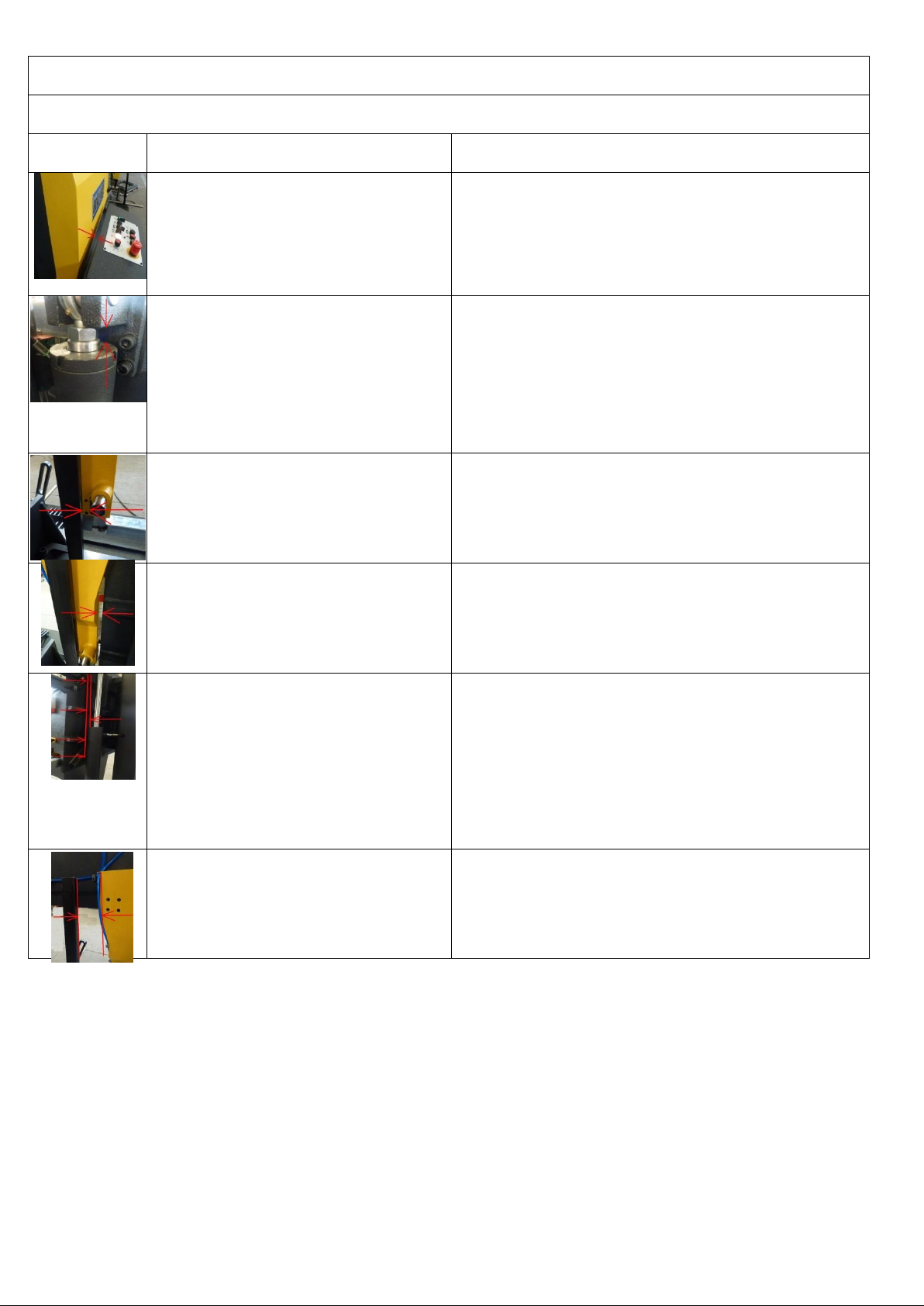
Residual Risks
Do Not Touch Below Mentioned Moving Or Movable Parts Of The Machine While İt Runs.
Mechanical Dangers
Residual Risks
There might be the risk of hand/arm
incerceration between wheel cover and
control panel.
Necessary warnings are mentioned in the manual.
There are warning signs on the machine.
There might be the risk of hand incerceration
between piston hose and piston when the
head is down.
There is necessary and enough warnings in the manual.
There is warning sign at first part. There is warning sign on the
cover.
There might be the risk of hand/arm
incerceration between movable vice profile
and arm withdraw point.
There is necessary and enough warnings in the manual.
Warning sign has been put at related section.
There might be the risk of hand/arm
incerceration between arm and ear when
movable arm is at last point
There is necessary and enough warnings in the manual.
Warning sign has been put at related section.
There might be the risk of hand/arm
incerceration between hydraulic lifting piston
pipe and lug support profile, movable arm
piston pipe and piston upper connection
block during the up and down movement of
bow .
There is necessary and enough warnings in the manual.
Warning sign has been put at related section.
There might be snipping risk between
movable vice profile and movable arm
There is necessary and enough warnings in the manual.
Warning sign has been put at related section.

Warning
This chapter outlining the safety devices and norms was drawn up bearing in mind the normal use
of the machine as stated in the chapter on the operation of the machine and the adequate
preparation of the operators as regards the specific risks linked to the operation of the machine.
İf the machine isn’t used according to instruction given in the ‘purpose of the machine’ chapter in
this manual, the manufacturer isn’t responsible for any damage caused to people and things.
Furthermore, the manufacturer isn’t responsible for any damage to people and things and things
resulting from the non-compliance with the following warnings.
A) Adopt all the necessary precautions during loading, calibration, part replacement,
cleaning, and repair or maintenance operations to prevent someone else from turning
the machine on.
B) Do not temper with the safety devices and guards on the machine.
C) Do not remove any of the safety devices and guards on the machine.
Always make sure that safety devices and guards are remounted after their temporary removal for
technical reasons ordered by the boss
Connection To The Electrical System
Control panel is mounted on the electric panel. Machine is connected to the main
supply in the electrical panel. R, s and t shows the phases, n is neuter and pe is
grounding. Connection will be from the 13(l1) klemens which is at right klemens group.
Check the voltage which is mentioned at the first page of the manuel before setting the
electrical connection of the machine.
İf the cable phase line is correct phase control led lightens in that way it is prevented to
motors move on wrong ways. Be sure that the out-put voltage at the power supply is 22 ~ 28
vdc.
The machine is protected against short circuit with interrupters and against high voltage with
thermal relays. Grounding and neutralizing have to be done to protect the machine .
Technical Data
TECNICAL DATA/TECHNISCE DATEN
BMSY 810CGH
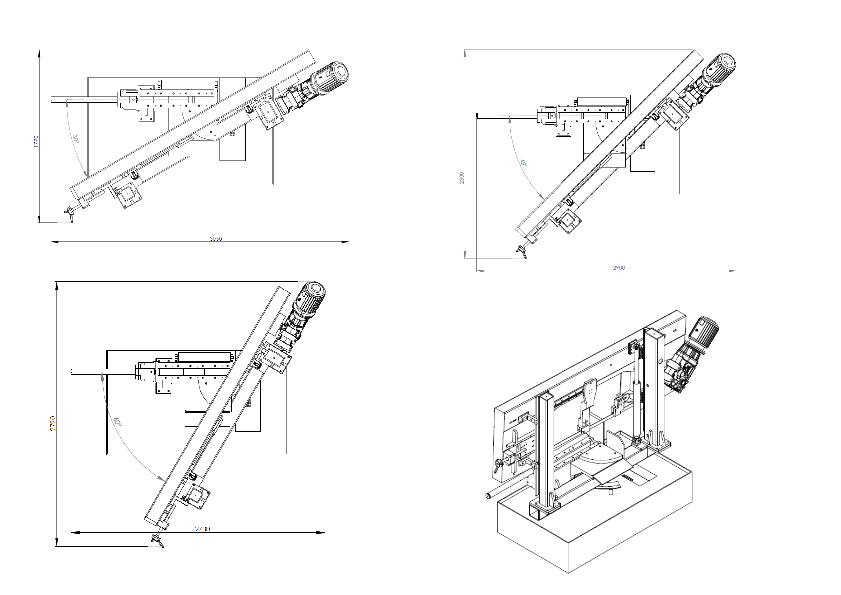
Cutting Capacity
Schnittbereich
0°
Round/Rund
mm
810
Flat/Flach
mm
810 x 770
Square/Vierkant
mm
770
Cutting Capacity
Schnittbereich
+30°
Round/Rund
mm
670
Flat/Flach
mm
650 x 770
Square/Vierkant
mm
650
Cutting Capacity
Schnittbereich
+45°
Round/Rund
mm
530
Flat/Flach
mm
500 x 750
Square/Vierkant
mm
520
Cutting Capacity
Schnittbereich
+60°
Round/Rund
mm
320
Flat/Flach
mm
310 x 750
Square/Vierkant
mm
320
Main Drive Motor/Hauptmotor
kW
4
Hydraulic Motor/Hydraulikmotor
kW
1,5
Coolant Motor/Kühlmittelpumpe
kW
0,12
Chip Conveyor Motor/Spaneförderer
kW
0,25
Cutting Speeds/Schnittgeschwindigkeit
m/min
20 - 100
Band Dimensions/Sagebandabmessung
mm
8200 x 41 x 1,3
Working Height/Arbeitshöhe
mm
725
Weight/Gewicht
Kg
3100
Dimensions/Masse
Length/Länge
mm
3940
Width/Breite
mm
1300
Height/Höhe
mm
2500
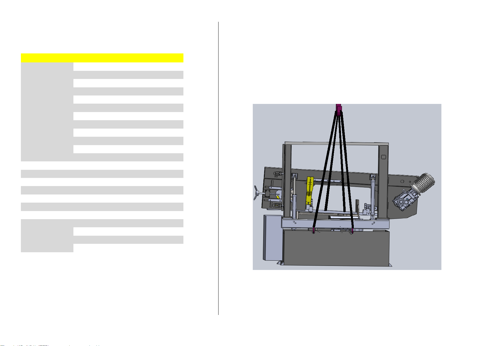
Transportation And Carrying Of Machine
İmportant
Carry well-balanced with a strong rope which will be hooked to carrying rings.
Bekamak may change the properties of the product without notice.


Statement of Noise
Conditions for measurement
Tested Machine: BMSY 810CGH –Blade size: 8200x 41 x 1,3mm
Material in use: ø250 Solid Material
A Nominal sound pressure level in warehouse
Lpfa,1m=77db(a) Coefficient of uncertainty k:4 db (testing appropriate to en 11202)
A nominal sound power level
Power level lwa=69,7db(a) (mesaured value)
Coefficient of uncertainty k:4 db (testing appropriate to en iso 3476)
Values for noise are level of issue and it doesn’t state it’s on safe working level. Even there is a connection betweeen İssue and exposure levels, this can not be used safely to decide if
advanced precautions are needed. Factors that effect the real level of exposure that effects work force are depending on featuress of warehouse,(other sourses of noise, other works nearby,
and quantity of machines) including exposure time
Allowed level of exposure may change from country to another. Beside these, this information lets the operator to consider the dangers and risks.
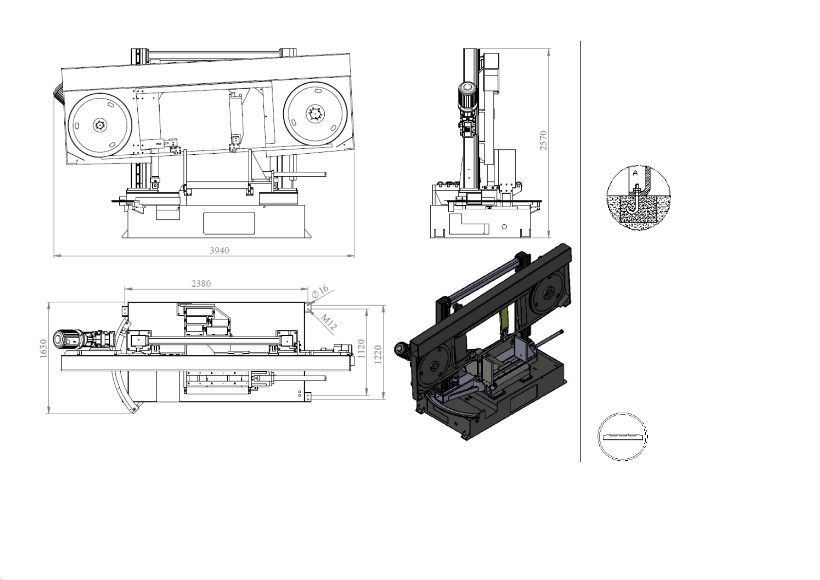
Fixing
Area that machine will be fixed should be flat and
bowless. Machine base should be placed properly
, linear and diagonal way . Get the machine to
balance with 4pcs m16screws that are on the
legs, you should fix it with ø13 steel pins.
Balancing The Machine
balancing the machine can be achieved
by using the height adjustable screws. The
machine must be balanced on both directions.
Important : balance of the machine is one of the
most important factors for the correct working of
the machine.

OPERATING INSTRUCTION
SPEED CONTROL POTMETER : CONTROLS THE
INVERTER TO ADJUST THE TURNING SPEED OF
BLADE
EMERGENCY STOP
BUTTON:PREVENTS ACCIDENTS AT
UNEXPECTING SITUATIONS.
START BUTTON : START THE CUTTING
STOP BUTTON :STOPS THE CUTTING
Sıgnal button : Power supply off/on
COOLANT BUTTON : IT IS USED TOL
ET THE COOLANT LIQUID FLOW.
BOW UP BUTTON: MOVES THE BOW UP MANUALLY
AND STOPS CUTTING.
BOW DOWN BUTTON: MOVES DOWN
THE BOW MANUALLY.
START(READY)BUTTON:ENERGISESPOWER CIRCUIT OF THE
MACHINE
VICE PRES BUTON:IT IS USED TO
PRESS THE MATHERIAL
BLADE TIGHTENING BUTTON: TIGHTEN THE
BLADE.
TOP CLAMPING
SELECTOR(OPTIONAL): THIS OPTION
IS FOR TIGHTENINK THE MATERIAL
VERTICALLY FOR BUNDLE CUTTING
ADJUSTING DOWN FEED SPEED: THIS VALVE IS
USED TO SET DOWN FEED SPEED AFTER ADJUSTING
THE CUTTING PRESSURE. SPEED ISCHANGED BYB
OBSERVING CHIPS COMING OUT FROM CUTTING
MATERIAL. AT ADEQUATE SPEED CHIPS ARE
CLEAN AND UNBURNED .
ANGLE DISPLAY: DISPLAYS THE
POSITION OF BOW IN DEGREES
BETWEEN 0° AND +60°
The indicator of manometer must be in the green area (area ii). If the indicator is in one of the red area, this means that the
tension of the blade is not in the acceptable level and it may cause unwanted results.
Area ı: this shows that the tension of the blade is less than it must be. Adjust the blade tension.
Area ıı : this shows that the tension of the blade is normal
area ııı : this shows that the tension of the blade is more than it must be. This may break
the blade. Reduce the tension.
HYDRAULIC VICE : BAR / MAIN MOTOR: BAR
HYDROMECANIC BLADE TENSION: BAR / HYDRAULIC BLADE TENSION:
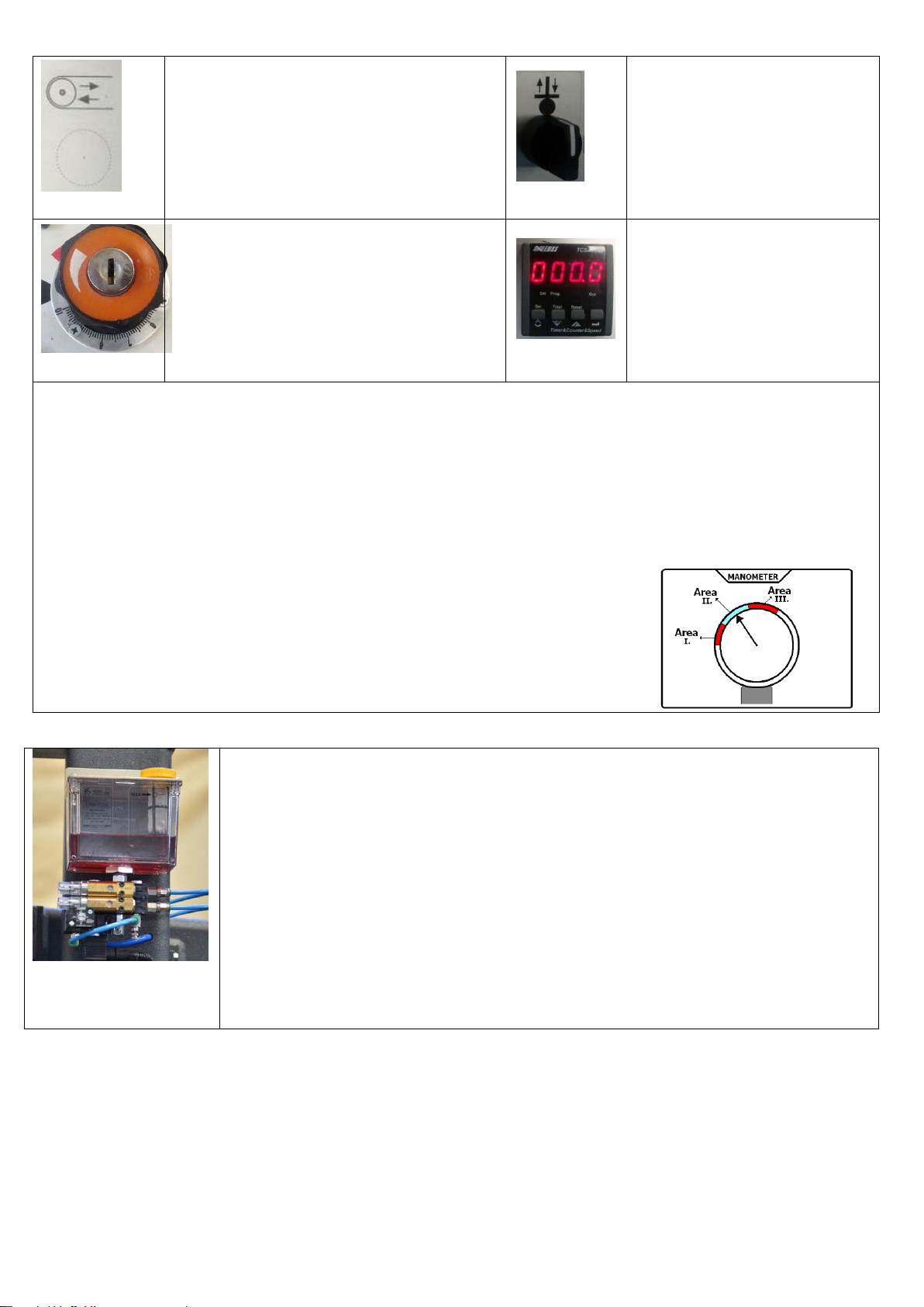
Microspray (optional):
To enchance more qualified cutting procudure and to protect saw blade microspray system is
applied instead of coolant liquid system. To coolant the blade pulverised microspray oil and
pressured air is sprayed via the nozzle on the saw blade . Oil level can be traced from indicates
of min.- max. On oil contanier. Oil amount, air amount, lubrication sequence can be adjusted
from device.
Air pressure : min.4, max6 bar
Oil spesifications: kt/2000

Manual Cuttıng Operatıon
1-Add coolant to the tank
2-Check level of hydraulıc oıl(ıso 46)
3-Swıtch on maın swıtch
4-See energy on lıght on the control pannel
5-If there ıs no lıght change places of ınput phases
6-Press machıne ready button
7- Push bow up tıll ıt’s enough for materıal to be cut
8-Open the vıce by turnıng the related button.
9-Place the materıal. Adjust the lenght to be cut by lean shaft and close vıce jaws and fıx the materıal.
10-The saw wıll not start up unless the materıal ıs not clamped wıt approprıate pressure.
11-Start the saw by pressıng start button.
12-Determıne the approprıate saw cuttıng speed and turn on the coolant accordıng to your need.
13-Due to the materıal detectıon sensors on the machıne approached to the materıal fastly and then passes to the speed whıch ıs
adjusted by the valve.
14-When the machıne runs to the cuttıng speed , the coolant starts as well.
15-Cuttıng speed of the machıne should be adjusted accordıng to the materıal and chıp after cuttong process. For example; ıf the chıp
ıs burnt after the cuttıng that means the speed ıs too fast. That ıs not proper for the machıne and the blade.
16-After cuttong process the balde wıll rıse up and stop automatıcally.
17-The same should be done for the second cuttng.
18-Durıng the tıme there mıght pıle up chıp ınfront of the sensors , thıs mıght cause workıng problem to the machıne; to avıod that , the
wheel covers should be opened regularly and chıp should be cleaned.

Sensor Parts
(1)Blade broken pressure switch: this switch stops the main motor when the blade is broken and provides protection of
the operator and the machine from the damages that a broken blade can cause.
(2)Lower limit switch: this limit switch stop the main motor and starts the bow’s upwards movement.
(3)Laser: It is used as a marker for indicating first touching point of the blade to material.
(4)Maximum switch: this switch sets the top point that bandsaw reaches.
(5)Digital Angle Encoder:It is using for reading the angle of bow.
(8)Fotocell: this switch starts the main motor when the blade approaches to the material about 30 mm after the bow begins
going down when start button is pressed. And in manual use, this switch stops the movement before the bow crashes to
material when the bow is going down.
(9)Protection cover switches: this switch
stops the machine if any cover is open.
1- Blade Broken Pressure Switch
2- Lower Limit Switch
3- Lazer
4- Maximum Switch
5- Dijital Encoder
6- Wheel Reductor
7- Wheel Motor
8- Protection Cover Switch
9- Fotocell

MACHINE MAINTENANCE INSTRUCTIONS
1)Daily Maintenance
1) Clean the chips behind the wheels. 1.2. a) How the chip conevyor removes the chips
1.2 b) Chip conveyor cover. 1.2 c) Coolant oil tank
1.2 d) How to remove the chips from oil tank. 1.3) Clean the chips from the vice block

1.4) Lubricate the upper clamping blocks. 1.5) Clean the vice clamping shaft.
1.6) Lubricate the vice clamping shaft. 1.7 a) Coolant hoses
1.7 b) How to air the hoses mentioned above. 1.8) How to clean the tensioning rails

1.9) The manometer should be at 43 bars.
2) Weekly maintenace
2.1) Check the gearbox oil level (no 90) 2.2) Hydraulic oil tank oil level should ve between upper and lower levels. No 46
2.3) Remove the chips from the tank with shovel. 2.4 ) New type coolant case.
Table of contents
Other Beka-Mak Saw manuals


