Beka-Mak BMSY 360CGH User manual


MANUFACTURER / İMALATÇİ : BEKA-MAK MAKİNA SANAYİ VE TİC. A,Ş.
Address / Adres: İzmir Yolu 25.km Marmarabirlik yani 16370 Başköy-Bursa/Türkiye
Telefon : 02244490361 (4 hat )
Fax : 02244490360 Nilüfer / Bursa
Http : // www.bekamak.com.tr
E-mail : [email protected]
Warranty
-The firm guarantees the machine described hereby, designed in compliance with all regulations
in force, in particular safety and health regulations; the machine has undergone successful
testing.
-The warranty covers a period of 12 months. İt doesn’t cover electrical motors and tools.
-The purchaser is entitled ‘replacement of faulty parts’. Shipping and packing costs are at his
expense.
-The warranty doesn’t cover the parts damaged by falls or careless handling of the machine,
incorrect operation, non -compliance with the maintenance rules. Any tampering with the
machine, especially with the safety devices automatically expires the warranty and the
manufacturer will be freed from any responsibility.
-Any kind of alteration on the machine ends the warranty and the manufacturer becomes free
from every kind of responsibility.
-No claim for damages shall be accepted in case the machine lays idle for a long period of time.
-Machine is designed to be run indoors. İt is not recommended to run the machine outdoors.
The serial number on the machine is a ‘main reference for the warranty’, instructions manual, after
sale service and identify the machine in case of need.
Important
Upon the delivery of the machine, the consumer must make himself sure that all
the devices indicated in the paragraph of the safety manual are present and working
correctly. Furthermore, he must mount in conformity with the instructions indicated those
devices which are not mounted at the time of delivery to facilitate transport.
When ordering spare parts
İt is necessary to state:
ØMachine model
ØSerial number and year of production
Øİtem reference number
Without serial number no spare parts will be delivered

General İnformation
-The machines are manufactured in compliance with the accident prevention rules in
force.
-Strictly comply with the instructions contained in this manual to obtain the best
performance from the machine. Strict compliance with the rules co ntained herewith will
ensure optimum results and avoid any inconvenience caused by the non -compliance of
operation and maintenance instructions.
-Closely follow the instructions given below to avoid contacting the manufacturer for the
problems which can be easily solved..
-If after having strictly compliance with the given instructions, the purchaser still needs
the help of our technical assistance service, he must supply all the technical indications
necessary to determine the type of problem and/or the parts which are not functioning
correctly. This will enable our technical assistance service to intervene quickly and
efficiently on the machine.
Copies of the instruction manual may be requested upon indication of the machine serial
number.
General Safety Notes
All installation work including the electrical connection must only be carried out by qualified
personnel.
The machine must only be operated by a technically trained and experienced operative who is
also instructed in ‘safety at work ’ procedures.
Any adjustments, cleaning, repairs or changing of the saw blade must under no circumstances be
performed unless the machine is fully isolated from the electrical power supply. Ensure the
emergency stop button on the control binnacle is pressed and the power supplies at the mains are
disconnected.”
The band saw must be regularly inspected and maintained in good serviceable condition. Eye
protection, ear protection, gloves and protective clothing must be worn when any of the above
procedures are being carried out, as well as when cutting fluid is prepared, introduced or displaced
from the band saw machine (the relevant environmental regulations must be observed in case of
the use and disposal of cutting fluid etc.)
The band saw must be installed on ground. Obs erve the permissible floor load. Than the band
saw machine has been properly bolt to ground securely.
Allow sufficient working space around the band saw of at least 1 meter. İnstallations of stock roller
conveyors require additional space and possibly a lifting mechanism for heavy work pieces.
Always ensure that the working area around the band saw is well lit.

Safety İnstructions
ØBe sure that electrical connection is made carefully. To avoid unwanted situations like electrical shock, protect the mainsupply cable with a holster.
ØBefore running the machine, be sure that all of the protections are mounted properly and all the covers are closed.
ØAvoid from smoke and moisture.
ØPlease use the parts and equipments which are recommended. Usage of unsuitableparts and materials which are bigger than the capacity of the machine can cause unwanted situations.
ØCheck the machine and inform the defects everyday.
ØDon’t leave any material after chancing the band.
ØDo not hold the material while the machine is cutting. Always tighten the material by using essential parts.
ØPlease pay attention to choose the area of the machine which doesn’t include anything that creates difficulties to control the machine
ØPlease be sure that the teeth of the band are looking to correct direction.
·Don’t leave the band on the ground or any place that is dangerous for other people.
·Be careful when using the machine and keep the working area clean ( clean the saw dusts and oil traces )
·Pay attention to security instructions when using the machine.
·Don’t wear loose cloths when using the machine.
·Regardless use the protective gloves when using the machine.
·Don’t get close too much to the machine when running.
·Before carrying out any cleaning or maintenance procedure, disconnect the machine from main supply.
·İn some conditions, noise level can be about 85 db. Band choice and cutting speed is important factor for noise level.
·İllumination is an important factor for security.
·Ratio of coolant liquid is important for obtaining optimum lubrication.
·Never use the machine if you notice any fault of the machine or absence of any part of the machine.
-Control the emergency button at least once a week and be sure that it is working properly.

RELATED DIRECTIVES AND STANDARDS / ILGILI YÖNETMELIK VE STANDARTLAR
DIRECTIVES/DIREKTIFLER
MACHINERY DIRECTIVE-/MAKINE DIREKTIFI 2006/42/EC
LOW VOLTAGE DIRECTIVE/DÜŞÜK VOLTAJ DIREKTIFI 2006/95/EC
ELECTROMAGNETIC COMPATIBILITY DIRECTIVE/ELEKTRO MANYETIK UYUMLULUK DIREKTIFI- 2004/108/EC
STANDARDS/STANDARTLAR
EN ISO 13857:2008; SAFETY OF MACHINERY-SAFETY DISTANCES TO PREVENT DANGER ZONES BEING REACHED BY UPPER LOWER LIMBS/ KOL VE BACAKLARIN
ULAŞABILECEĞI BÖLGELERDE TEHLIKENIN ÖNLENMESI IÇIN GÜVENLIK MESAFELERI
EN ISO 4413:20106: HYDRAULIC FLU ID POWER – GENERAL RULES AND SAFETY REQU IREMENTS FOR SYSTEMS AND THE IR COMPONENTS / H IDROLIK AK IŞKAN GÜÇ –
SISTEMLER VE BILEŞENLERI IÇIN GÜVENLIK KURALLARI VE GENEL KURALLAR.
EN ISO 13849-1:2008/AC:2009; SAFETY OF MACH INERY - SAFETY-RELATED PARTS OF CONTROL SYSTEMS - PART 1: GENERAL PR INCIPLES FOR DES IGN / MAKINELERDE
GÜVENLIK- KUMANDA SISTEMLERININ GÜVENLIKLE ILGILI KISIMLARI- BÖLÜM 1: TASARIM IÇIN GENEL PRENSIPLER
EN 13898:2003+A1:2009/AC:2010: MACHINE TOOLS - SAFETY - SAWING MACH INES FOR COLD METAL /TAKIM TEZGÂHLARI – GÜVENLIK - METALLERI SOĞUK IŞLEME IÇIN
TESTERE TEZGAHLARI
EN ISO 12100:2010; SAFETY OF MACH INERY - GENERAL PR INCIPLES FOR DES IGN – RISK ASSESMENT AND R ISK REDUCT ION/ MAKINALARDA GÜVENL IK – TASARIM IÇIN
GENEL PRENSIPLER- RISK DEĞERLENDIRILMESI VE RISK AZALTILMASI.
EN 60204-1:2006/A1:2009; SAFETY OF MACH INERY - ELECTRICAL EQUIPMENT OF MACHINES - PART 1: GENERAL REQU IREMENTS / MAKINELERIN EMNIYETI – MAKINELERIN
ELEKTRIK DONANIMI – BÖLÜM 1: GENEL GEREKLER
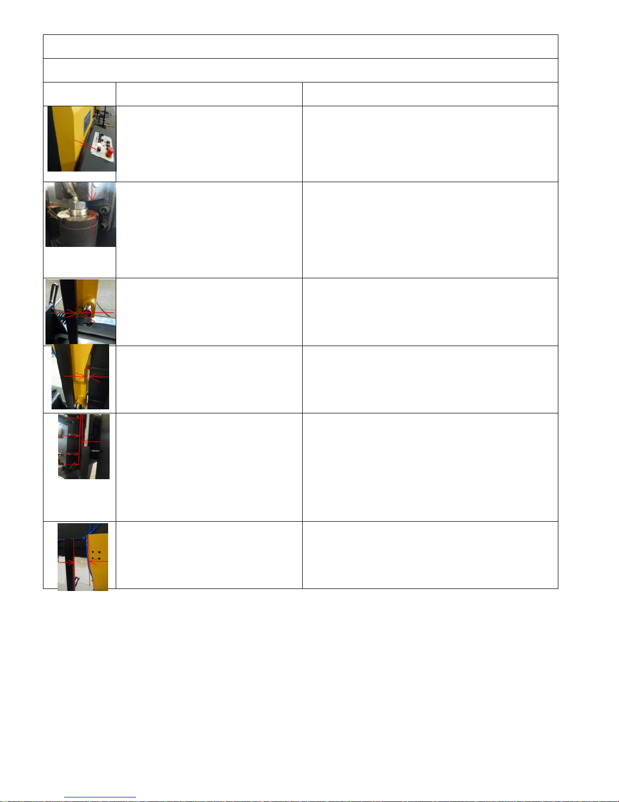
Residual Risks
Do Not Touch Below Mentioned Moving Or Movable Parts Of The Machine While İt Runs.
Mechanical Dangers
Residual Risks
There might be the risk of hand/arm
incerceration between wheel cover and
control panel.
Necessary warnings are mentioned in the manual.
There are warning signs on the machine.
There might be the risk of hand incerceration
between piston hose and piston when the
head is down.
There is necessary and enough warnings in the manual.
There is warning sign at first part. There is warning sign on the
cover.
There might be the risk of hand/arm
incerceration between movable vice profile
and arm withdraw point.
There is necessary and enough warnings in the manual.
Warning sign has been put at related section.
There might be the risk of hand/arm
incerceration between arm and ear when
movable arm is at last point
There is necessary and enough warnings in the manual.
Warning sign has been put at related section.
There might be the risk of hand/arm
incerceration between hydraulic lifting piston
pipe and lug support profile, movable arm
piston pipe and piston upper connection
block during the up and down movement of
bow .
There is necessary and enough warnings in the manual.
Warning sign has been put at related section.
There might be snipping risk between
movable vice profile and movable arm
There is necessary and enough warnings in the manual.
Warning sign has been put at related section.

Warning
This chapter outlining the safety devices and norms was drawn up bearing in mind the normal use
of the machine as stated in the chapter on the operation of the machine and the adequate
preparation of the operators as regards the specific risks linked to the operation of the machine.
İf the machine isn’t used according to instruction given in the ‘purpose of the machine’ chapter in
this manual, the manufacturer isn’t responsible for any damage caused to people and things.
Furthermore, the manufacturer isn’t responsible for any damage to peop le and things and things
resulting from the non-compliance with the following warnings.
A) Adopt all the necessary precautions during loading, calibration, part replacement,
cleaning, and repair or maintenance operations to prevent someone else from turning
the machine on.
B) Do not temper with the safety devices and guards on the machine.
C) Do not remove any of the safety devices and guards on the machine.
Always make sure that safety devices and guards are remounted after their temporary removal for
technical reasons ordered by the boss
Connection To The Electrical System
Control panel is mounted on the electric panel. Machine is connected to the main
supply in the electrical panel. R, s and t shows the phases , n is neuter and pe is
grounding. Connection willbe from the 13(l1) klemens which is at right klemens group.
Check the voltage which is mentioned at the first page of the manuel before setting the
electrical connection of the machine.
İf the cable phase line is correct phase control led lightens in tha t way it is prevented to
motors move on wrong ways. Be sure that the out-put voltage at the power supply is 22 ~ 28
vdc.
The machine is protected against short circuit with interrupters and against high voltage with
thermal relays. Grounding and neutralizing have to be done to protect the machine .

Technical Data
TECNICAL DATA/TECHNISCE DATEN
BMSY 360CGH
Cutting Capacity
Schnittbereich
0°
Round/Rund
mm
360
Flat/Flach
mm
700 x 360
Square/Vierkant
mm
360
Cutting Capacity
Schnittbereich
+30°
Round/Rund
mm
360
Flat/Flach
mm
590 x 360
Square/Vierkant
mm
360
Cutting Capacity
Schnittbereich
+45°
Round/Rund
mm
360
Flat/Flach
mm
460 x 360
Square/Vierkant
mm
360
Cutting Capacity
Schnittbereich
+60°
Round/Rund
mm
305
Flat/Flach
mm
305 x 360
Square/Vierkant
mm
305
Main Drive Motor/Hauptmotor
kW
3
Hydraulic Motor/Hydraulikmotor
kW
0,55
Coolant Motor/Kühlmittelpumpe
kW
0,12
Chip Conveyor Motor/Spaneförderer
kW
0,25
Cutting Speeds/Schnittgeschwindigkeit
m/min
20 - 100
Band Dimensions/Sagebandabmessung
mm
5000 x 34 x 1,1
Working Height/Arbeitshöhe
mm
690
Weight/Gewicht
Kg
1550
Dimensions/Masse
Length/Länge
mm
2850
Width/Breite
mm
780
Height/Höhe
mm
1800
Transportation And Carrying Of Machine
İmportant
Carry well-balanced with a strong rope which will be hooked to carrying rings

Statement of Noise
Conditions for measurement
Tested Machine: BMSY 360CGH–Blade size: 5000 x 34 x 1,1mm
Material in use: ø250 Solid Material
A Nominal sound pressure level in warehouse
Lpfa,1m=77db(a) Coefficient of uncertainty k:4 db (testing appropriate to en 11202)
A nominal sound power level
Power level lwa=69,7db(a) (mesaured value)
Coefficient of uncertainty k:4 db (testing appropriate to en iso 3476)
Values for noise are level of issue and it doesn’t state it’s on safe working level.Even there is a connection betweeen İssue and exposure levels, this can not be used safely to decide if advanced
precautions are needed. Factors that effect the real level of
exposure that effects work force aredepending on featuress of warehouse,(other sourses of noise, other works nearby, and quantity of machines) including exposuretime
Allowed level of exposure may change from country to another. Beside these, this information lets the operator to consider the dangers and risks.
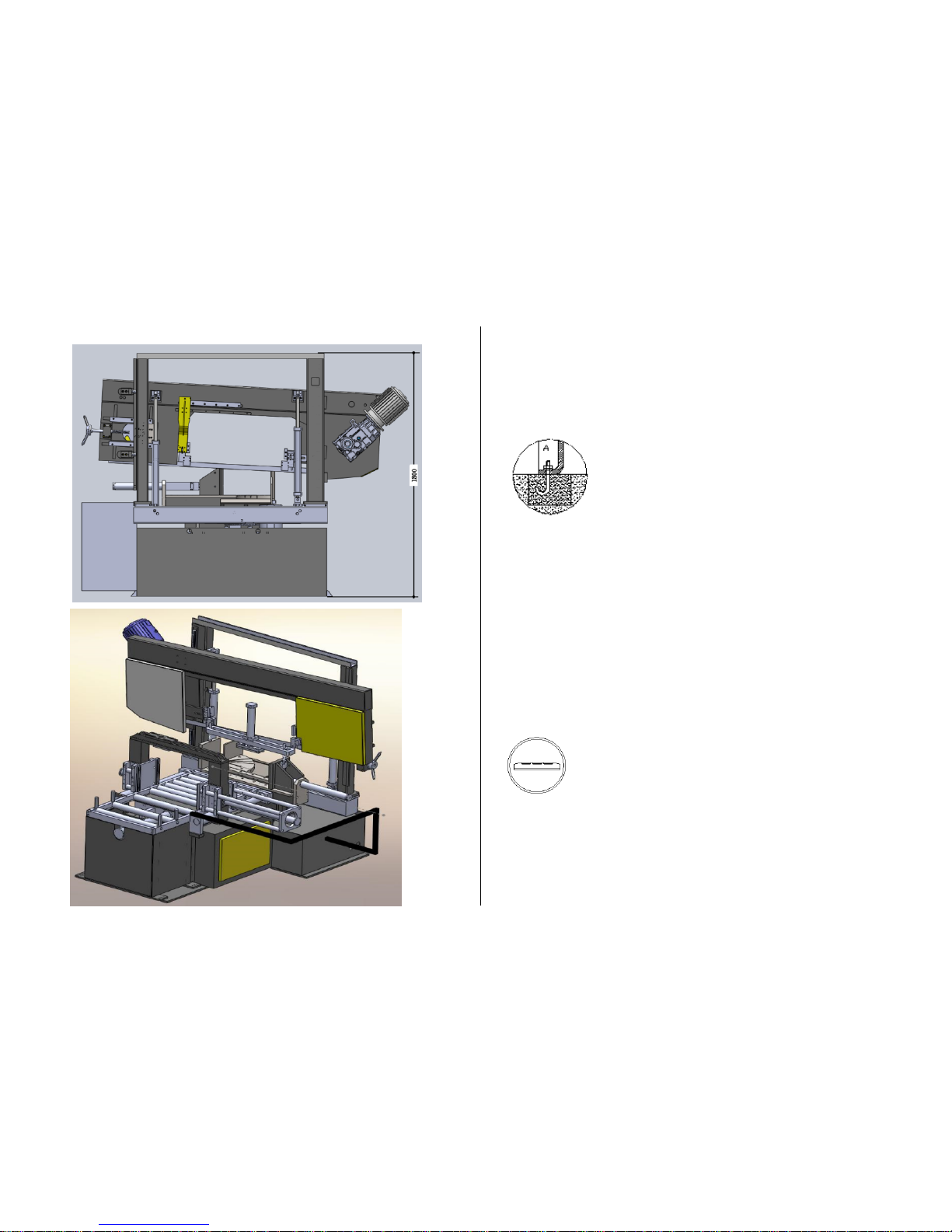
Fixing
Area that machine will be fixed should be flat and bowless. Machine base should be placed
properly , linear and diagonal way . Get the machine to balance with 4pcs m12 screws that
are on the legs, you should fix it with ø13 steel pins.
Balancing The Machine
balancing the machine can be achieved by using the height adjustable screws. The
machine must be balanced on both directions.
Important : balance of the machine is one of the most important factors for the correct
working of the machine.


OPERATING INSTRUCTION
SPEED CONTROL POTMETER :CONTROLS THE
INVERTER TO ADJUST THE TURNING SPEED OF
BLADE
EMERGENCY STOP
BUTTON:PREVENTS ACCIDENTS AT
UNEXPECTING SITUATIONS.
START BUTTON : START THE CUTTING
STOP BUTTON :STOPS THE CUTTING
SIGNAL BUTTON : SHOW SIF THERE IS A PROBLEM
AT THE MACHINE.
COOLANT BUTTON :IT IS USED TOL
ET THE COOLANT LIQUID FLOW.
BOW UP BUTTON: MOVES THE BOW UP MANUALLY
AND STOPS CUTTING.
BOW DOWN BUTTON: MOVES DOWN
THE BOW MANUALLY.
START (READY) BUTTON:ENERGISES POWER CIRCUIT OF THE
MACHINE
VICE PRES BUTON: IT IS USED TO
PRESS THE MATHERIAL

BLADE TIGHTENING BUTTON: TIGHTEN THE
BLADE.
TOP CLAMPING
SELECTOR(OPTIONAL): THIS OPTION
IS FOR TIGHTENINK THE MATERIAL
VERTICALLY FOR BUNDLE CUTTING
DOWN FEED SPEED ADJUSTMENT: ADJUST SPEED
ACCORDING TO HARDNESS OF MATERIAL TO BE
CUT. WHEN BLADE BECOMES BLUNT CHOOSE A
LOWER SPEED TO HAVE A BETTER CUT.
ANGLE DISPLAY: DISPLAYS THE
POSITION OF BOW IN DEGREES
BETWEEN 0° AND +60°
The indicator of manometer must be in the green area (area ii). If the indicator is in one of the red area, this means that t he
tension of the blade is not in the acceptable level and it may cause unwanted results.
Area ı : this shows that the tension of the blade is less than it must be. Adjust the blade tension.
Area ıı : this shows that the tension of the blade is normal
area ııı : this shows that the tension of the blade is more than it must be. This may break
the blade. Reduce the tension.
HYDRAULIC VICE:40 BAR
HYDROMECANIC BLADE TENSION:300 BAR
HYDRAULIC BLADE TENSION:40 BAR
MAIN MOTOR:40 BAAR

Manual Cuttıng Operatıon
1-Add coolant to the tank
2-Check level of hydraulıc oıl(ıso 46)
3-Swıtch on maın swıtch
4-See energy on lıght on the control pannel
5-If there ıs no lıght change places of ınput phases
6-Press machıne ready button
7- Push bow up tıll ıt’s enough for materıal to be cut
8-Open the vıce by turnıng the related button.
9-Place the materıal. Adjust the lenght to be cut by lean shaft and close vıce jaws and fıx the materıal.
10-The saw wıll not start up unless the materıal ıs not clamped wıt approprıate pressure.
11-Start the saw by pressıng start button.
12-Determıne the approprıate saw cuttıng speed and turn on the coolant accordıng to your need.
13-Due to the materıal detectıon sensors on the machıne approached to the materıal fastly and then passes to the speed whıch ıs
adjusted by the valve.
14-When the machıne runs to the cuttıng speed , the coolant starts as well.
15-Cuttıng speed of the machıne should be adjusted accordıng to the materıal and chıp after cuttong process. For example; ıf thechıp
ıs burnt after the cuttıng that means the speed ıs too fast. That ıs not proper for the machıne and the blade.
16-After cuttong process the balde wıll rıse up and stop automatıcally.
17-The same should be done for the second cuttng.
18-Durıng the tıme there mıght pıle up chıp ınfront of the sensors , thıs mıght cause workıng problem to the machıne; to avıod that , the
wheel covers should be opened regularly and chıp should be cleaned.

Sensor Parts
(1)Blade broken pressure switch: this switch stops the main motor when the blade is broken and provides protection of
the operator and the machine from the damages that a broken blade can cause.
(2)Lower limit switch: this limit switch stop the main motor and starts the bow’s upwards movement.
(3)Laser: It is used as a marker for indicating first touching point of the blade to material.
(4)Maximum switch: this switch sets the top point that bandsaw reaches.
(5)Digital Angle Encoder:It is using for reading the angle of bow.
(8)Fotocell: this switch starts the main motor when the blade approaches to the material about 30 mm after the bow begins
going down when start button is pressed. And in manual use, this switch stops the movement before the bow crashes to
material when the bow is going down.
(9)Protection cover switches: this switch stops the machine if any cover is open.
1- Blade Broken Pressure Switch
2- Lower Limit Switch
3- Lazer
4- Maximum Switch
5- Dijital Encoder
6- Wheel Reductor
7- Wheel Motor
8- Protection Cover Switches
9- Fotocell
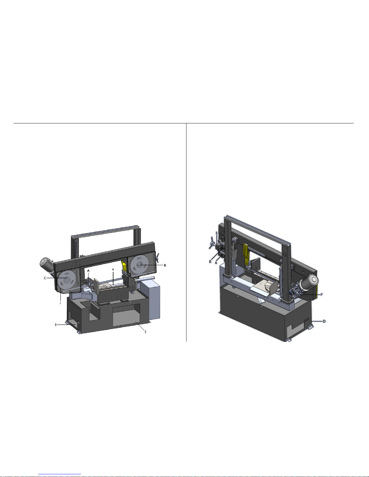
Instructıons For Maıntenance
Daıly Maıntenance
1-remove the chıps on wheel
2-clean the hydraulıc drawer
3- clean the chıps ın the boron oıl tank
pump aır to remove the dırth ın hoses
4. Remove the chıps at shaft and flat
5- manometer should be between ……………………. bar.
6. Clean the tensıonıng slıde flats.
Monthlty Maintenance
A-check the chıp brush.
B-fıll grease oıl from the hole on the tentıonıng shaft.
C- check the tıghtness of wheel bolts.
D.control the oıl level ın hydraulıc tank
E. Fıll grease oıl from the hole on the tensıonıng slıde
F-check the oıl level on reductor from dısplay ıncase of decreasıng add gear oıl (number
90)

Changing The Hydraulic Oil
Pouring Out The Hydraulic Oil
üLower down until it receives the cutting head.
üRemove hydraulic hose union at head lifting
üPut the removed hydraulic end of the hose into a container.
üEmpty the oil by pressing head lifting button at control panel.
After empting the oil, fix the hydraulic hose union to the same place.
Refilling the hydraulic oil
The hydraulic oil filling
üRemote the bolts of hydraulic drawer, then pull it out.
üOpen the store cover.
üPour 46 numbered iso hydraulic oil into tank. (8lt capacity.)
üClose the tank cover and move the drawer into the body
Fasten the screws to the body again with the help of hydraulic drawer.
Filling Of Coolant
Consisting of a mixture of liquid and water coolant liquid should be used for steel cutting. Coolant should not be used for cutting casting. Specific periods of time (at least once a month)
, coolant should be drained and clean chips. İf amount of coolant is not enough, add to the tank. (4 liters of tank capacity. Collant mixing ratio 1/10)
Setting New Blade
·First of all both guard flaps and the guards which are on the guide arms have to be open upwards.
·Loosen the blade by the hand level so far that the blade can be easily taken off around the pulleys
·The same way but vic averse, fit and tighten the new blade. There is also possibility to tighten the blade by torque meter.
·Always pay attention to the teeth of the blade’s direction is correct. İf not correct it.
Cutting Speeds
The machine has two pre-selected cutting speeds of 20 and 100 m/sec. Cutting speeds has to be selected according to the grade and dimensions of the m aterial. İf any vibration and/or
noise raises from the blade, change the speed.
·All the details about the cutting of various materials and dimensions are given below

CUTTING RECOMENDATIONS
NOTE:THE CUTTING SPEEDS GIVEN BELOW ARE GUIDELINES ONLY
MATERIAL
MATERIAL DESIGNATION
DIN
MATERIAL
NO
CUTTING SPEED
COOLANT
SPECIAL
LG-SUPER
BI-
METAL
EMULSION
CUTTING OIL
YES
NO
STRUCTUAL STEEL
ST 35 – ST 42
1.0308-
0077
40 - 55
60 - 80
1:10
X
ST 350 – ST 70
1.0052-
0070
30 - 45
50 - 70
1:20
X
HARDENING STEEL
C 10 - C 16
1.0301-
0401
45 - 65
60 - 90
1:10
X
14 NICR 14
1.5752
30 - 40
40 – 50
1:10
X
21 NICR MO 2
1.6523
30 - 45
45 - 55
1:10
X
16 MRCR 5
1,7131
30 - 45
50 - 65
1:10
X
NITRICTED STEEL
(HEAT TREATED)
34 CRAL 6
1,8504
------
20 - 35
1:20
X
34 CR AL NI 7
1,8550
------
20 - 35
1:20
X
FREE CUTTING STEEL
9 S 20
1,0711
45 - 65
70 - 120
1:10
X
HEAT TREATABLE STEEL
C 35 C 45
1,0501-
0503
35 - 55
55 - 75
1:20
X
41 CR 4
1,7035
35 - 35
40 - 60
1:20
X
40 MN 4
1,5038
35 - 45
50 - 65
1:20
X
42 CRMO 4
1,7225
30 - 40
35 - 50
1:20
X
36 NI CR 6
1,5710
30 - 40
50 - 60
1:20
X
24 NI CR 14
1,5754
25 - 35
40 - 60
1:20
X
BALL BEARING STEEL
100 - CR 6
1,3505
25 - 35
50 - 65
1:30
X
105 – CR 4
1,3503
25 - 35
50 - 65
1:30
X
100 – CRMO 6
1,3520
20 - 30
40 - 50
1:30
X
SPRING STEEL
65 SI 7
1,0906
30 - 40
40 - 60
1:30
X
50 CRV 4
1,8159
30 - 40
40 - 60
1:30
X
UNALLOYED TOOL STEEL
C 80 W 1
1,1525
25 - 35
50 - 60
1:30
X
C 125 W 1
1,1560
20 - 30
20 - 35
1:30
X
C 105 W 2
1,1645
25 - 35
40 - 50
1:30
X
ALLOYED TOOL STEEL
105 CR 5
1,2060
30 - 40
50 - 60
1:30
X
X 210 CR 12
1. 2080
------
20 - 35
------
X
X 40 CR MO V 51
1,2344
20 - 30
30 - 40
1:30
X
X 210 CR W 12
1,2436
------
20 - 30
------
X
X 165 CR MP V 12
1,2601
------
20 - 35
1:30
X
56 NICRMOV 7
1,2714
25 - 30
20 - 40
1:30
X
100 CRMO 5
1,2303
20 - 30
35 - 45
1:30
X
X 32 CRMOV 33
1,2365
20 - 30
30 - 45
1:20
X
HIGH SPEED STEEL
S 5-6-2
1,3343
------
25 - 40
1:30
X
S 5-6-2-5
1,3243
------
25 - 40
1:30
X
S 18-0-1
1,3355
------
25 - 40
1:30
X
S 18-1-2-10
1,3265
------
25 - 40
1:30
X
VALVE STEEL
X 45 CRSI 93
1,4718
------
30 - 40
1:20
X
X 45 CRNIW 189
1,4873
------
30 - 40
1:20
X
HIGH TEMPERATURE
STEEL
CRNI 2520
1,4843
------
25 - 40
1:10
X
X 20 CRMOV 211
1,4922
------
25 - 40
1:10
X
X5 NICRTI 2615
1,4980
------
25 - 40
1:10
X
HEAT RESISTING STEEL
X 10 CRAL 7
1,4713
------
20 - 35
1:10
X
X 15 CRNISI 25 / 20
1,4841
------
20 - 35
1:10
X
X 10 CRSI 6
1,4712
------
20 - 35
1:10
X
STAINLESS AND ACID
RESISTING STEEL
X 5 CRNI 189
1,4301
------
25 - 35
1:10
X
X 10 CRNIMPT 1810
1,4571
------
25 - 35
1:10
X
X 10 CR 13
1,4006
------
25 - 35
1:10
X
X 5 CRNIMO 1810
1,4401
------
25 - 35
1:10
X
STEEL CASTING
GS – 38
30 - 40
50 - 60
1:50
X
GS – 60
30 - 40
50 - 60
1:50
X
CAST IRON
GG – 16
30 - 40
40 - 50
------
X
GG – 30
30 - 40
40 - 50
------
X
GTW – 40
30 - 40
40 - 50
------
X
GTS – 65
30 - 40
40 - 50
------
X
HIGH TEMPERATURE
NICKEL ALLOYS
NIMONIC
2,4631
------
15 - 25
1:10
X
HASTELLOY
X 2.4972
------
15 - 25
1:10
X
INCONEL
2,4640
------
15 - 25
1:10
X
ALUMINIUM ALLOYS
AL 99,5
3,0255
80 - 300
100 - 700
1:10
X
ALMG 3
3,3535
80 - 300
100 - 700
1:10
X
BRONZE / TIN BRONZE
CUSN 6
2,1020
50 - 70
70 - 100
1:50
X
G – CUSN 10
2,1050
50 - 70
70 - 100
1:50
X
ALUMINIUM - BRONZE
CUAL 8
2,0920
30 - 45
50 - 70
1:30
X
CUAL 8 FE 38
2,0920,60
30 - 40
40 - 50
1:20
X
RED BRASS
G – CUSN 10 ZN
2,1086,01
30 - 45
70 - 100
1:50
X
G – CUSN 5 ZN PB
2,1096,01
30 - 45
70 - 100
1:50
X
BRASS
CUZN 10
2,0230
80 - 200
100 - 300
1:50
X
CUZN 31 S
2,0490
80 - 200
100 - 300
1:50
X
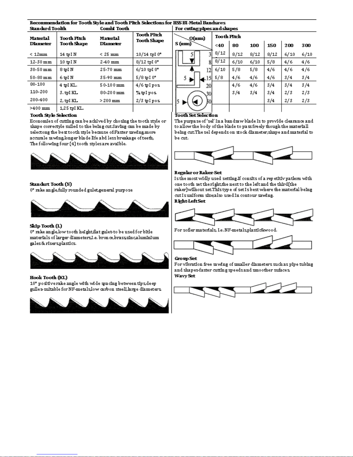
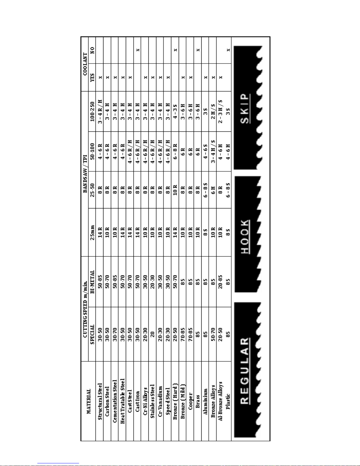
Table of contents
Other Beka-Mak Saw manuals


