Beka-Mak BMSO 325C User manual


Manufacturer / İmalatçi : Beka-Mak Makina Sanayi ve Tic. A,ş.
Address / Adres: İzmir Yolu 25.km Marmarabirlik yani 16370 Başköy-Bursa/Türkiye
Telefon : 02244490361 (4 hat )
Fax : 02244490360 Nilüfer / Bursa
Http : // www.bekamak.com.tr
E-mail : [email protected]
Warranty
-The firm guarantees the machine described hereby, designed in compliance with all regulations
in force, in particular safety and health regulations; the machine has undergone succe ssful
testing.
-The warranty covers a period of 12 months. İt doesn’t cover electrical motors and tools.
-The purchaser is entitled ‘replacement of faulty parts’. Shipping and packing costs are at his
expense.
-The warranty doesn’t cover the parts damaged by falls or careless handling of the machine,
incorrect operation, non -compliance with the maintenance rules. Any tampering with the
machine, especially with the safety devices automatically expires the warranty and the
manufacturer will be freed from any responsibility.
-Any kind of alteration on the machine ends the warranty and the manufacturer becomes free
from every kind of responsibility.
-No claim for damages shall be accepted in case the machine lays idle for a long period of time.
-Machine is designed to be run indoors. İt is not recommended to run the machine outdoors.
The serial number on the machine is a ‘main reference for the warranty’, instructions manual, after
sale service and identify the machine in case of need.
Important
Upon the delivery of the machine, the consumer must make himself sure that all
the devices indicated in the paragraph of the safety manual are present and working
correctly. Furthermore, he must mount in conformity with the instr uctions indicated those
devices which are not mounted at the time of delivery to facilitate transport.
When ordering spare parts
İt is necessary to state:
ØMachine model
ØSerial number and year of production
Øİtem reference number
Without serial number no spare parts will be delivered

General İnformation
-The machines are manufactured in compliance with the accident prevention rules in
force.
-Strictly comply with the instructions contained in this manual to obtain the best
performance from the machine. Strict compliance with the rules contained herewith will
ensure optimum results and avoid any inconvenience caused by the non -compliance of
operation and maintenance instructions.
-Closely follow the instructions given below to avoid contacting the manufact urer for the
problems which can be easily solved..
-If after having strictly compliance with the given instructions, the purchaser still needs
the help of our technical assistance service, he must supply all the technical indications
necessary to determine the type of problem and/or the parts which are not functioning
correctly. This will enable our technical assistance service to intervene quickly and
efficiently on the machine.
Copies of the instruction manual may be requested upon indication of the machine serial
number.
General Safety Notes
All installation work including the electrical connection must only be carried out by qualified
personnel.
The machine must only be operated by a technically trained and experienced operative who is
also instructed in ‘safety at work ’ procedures.
Any adjustments, cleaning, repairs or changing of the saw blade must under no circumstances be
performed unless the machine is fully isolated from the electrical power supply. Ensure the
emergency stop button on the control binnacle is pressed and the power supplies at the mains are
disconnected.”
The band saw must be regularly inspected and maintained in good servicea ble condition. Eye
protection, ear protection, gloves and protective clothing must be worn when any of the above
procedures are being carried out, as well as when cutting fluid is prepared, introduced or displaced
from the band saw machine (the relevant en vironmental regulations must be observed in case of
the use and disposal of cutting fluid etc.)
The band saw must be installed on ground. Observe the permissible floor load. Than the band
saw machine has been properly bolt to ground securely.
Allow sufficient working space around the band saw of at least 1 meter. İnstallations of stock roller
conveyors require additional space and possibly a lifting mechanism for heavy work pieces.
Always ensure that the working area around the band saw is well lit.

Safety İnstructions
ØBe sure that electrical connection is made carefully. To avoid unwanted situations like electrical shock, protect the main supply cable with a holster.
ØBefore running the machine, be sure that all of the protections are mounted properly and all the covers are closed.
ØAvoid from smoke and moisture.
ØPlease use the parts and equipments which are recommended. Usage of unsuitable parts and materials which arebigger than the capacity of the machine can cause unwanted situations.
ØCheck the machine and inform the defects everyday.
ØDon’t leave any material after chancing the band.
ØDo not hold the material while the machine is cutting. Always tighten the material by using essential parts.
ØPlease pay attention to choose the area of the machine which doesn’t include anything that creates difficulties to control the machine
ØPlease be sure that the teeth of the band are looking to correct direction.
·Don’t leave the band on the ground or any place that is dangerous for other people.
·Be careful when using the machine and keep the working area clean ( clean the saw dusts and oil traces )
·Pay attention to security instructions when using the machine.
·Don’t wear loose cloths when using the machine.
·Regardless use the protective gloves when using the machine.
·Don’t get close too much to the machine when running.
·Before carrying out any cleaning or maintenance procedure, disconnect the machine from main supply.
·İn some conditions, noise level can be about 85 db. Band choice and cutting speed is important factor for noise level.
·İllumination is an important factor for security.
·Ratio of coolant liquid is important for obtaining optimum lubrication.
·Never use the machine if you notice any fault of the machine or absence of any part of the machine.
-Control the emergency button at least once a week and be sure that it is working properly.

RELATED DİRECTİVES AND STANDARDS / İLGİLİ YÖNETMELİK VE STANDARTLAR
DİRECTİVES/DİREKTİFLER
MACHİNERY DİRECTİVE-/MAKİNE DİREKTİFİ 2006/42/EC
LOW VOLTAGE DİRECTİVE/DÜŞÜK VOLTAJ DİREKTİFİ 2006/95/EC
ELECTROMAGNETİC COMPATİBİLİTY DİRECTİVE/ELEKTRO MANYETİK UYUMLULUK DİREKTİFİ- 2004/108/EC
STANDARDS/STANDARTLAR
EN İSO 13857:2008; SAFETY OF MACHİNERY-SAFETY DİSTANCES TO PREVENT DANGER ZONES BEİNG REACHED BY UPPER LOWER LİMBS/ KOL VE BACAKLARİN
ULAŞABİLECEĞİ BÖLGELERDE TEHLİKENİN ÖNLENMESİ İÇİN GÜVENLİK MESAFELERİ
EN İSO 4413:20106: HYDRAULİC FLUİD POWER – GENERAL RULES AND SA FETY REQUİREMENTS FOR SYSTEMS AND THEİR COMPONENTS / HİDROLİK AKİŞKAN GÜÇ –
SİSTEMLER VE BİLEŞENLERİ İÇİN GÜVENLİK KURALLARİ VE GENEL KURALLAR.
EN İSO 13849 -1:2008/AC:2009; SAFETY OF MACHİNERY - SAFETY-RELATED PARTS OF CONTROL SYSTEMS - PART 1: GENERAL PRİNCİPLES FOR DESİGN / MAKİNELERDE
GÜVENLİK- KUMANDA SİSTEMLERİNİN GÜVENLİKLE İLGİLİ KİSİMLARİ- BÖLÜM 1: TASARİM İÇİN GENEL PRENSİPLER
EN 13898:2003+A1:2009/AC:2010: MACHİNE TOOLS - SAFETY - SAWİNG MACHİNES FOR COLD METAL /TAKİM TEZGÂHLARİ – GÜVENLİK - METALLERİ SOĞUK İŞLEME İÇİN
TESTERE TEZGAHLARİ
EN İSO 12100:2010 ; SAFETY OF MACHİNERY - GENERAL PRİNCİPLES FOR DESİGN – RİSK ASSESMENT AND RİSK REDUCTİON/ MAKİNALARDA GÜVENLİK – TASARİM İÇİN
GENEL PRENSİPLER- RİSK DEĞERLENDİRİLMESİ VE RİSK AZALTİLMASİ.
EN 60204-1:2006/A1:2009; SAFETY OF MACHİNERY - ELECTRİCAL EQUİPMENT OF MACHİNES - PART 1: GENERAL REQUİREMENTS / MAKİNELERİN EMNİYETİ – MAKİNELERİN
ELEKTRİK DONANİMİ – BÖLÜM 1: GENEL GEREKLER
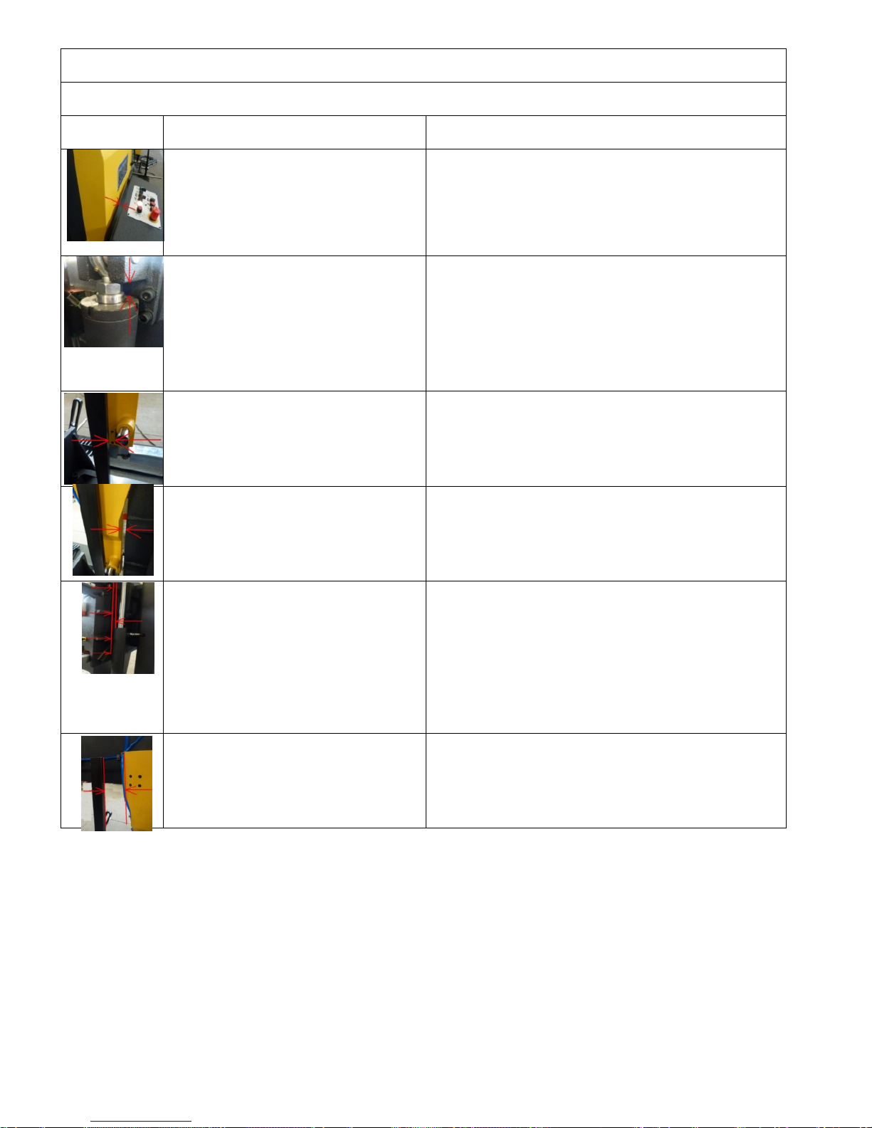
Residual Risks
Do Not Touch Below Mentioned Moving Or Movable Parts Of The Machine While İt Runs.
Mechanical Dangers
Residual Risks
There might be the risk of hand/arm
incerceration between wheel cover and
control panel.
Necessary warnings are mentioned in the manual.
There are warning signs on the machine.
There might be the risk of hand incerceration
between piston hose and piston when the
head is down.
There is necessary and enough warnings in the manual.
There is warning sign at first part. There is warning sign on the
cover.
There might be the risk of hand/arm
incerceration between movable vice profile
and arm withdraw point.
There is necessary and enough warnings in the manual.
Warning sign has been put at related section.
There might be the risk of hand/arm
incerceration between arm and ear when
movable arm is at last point
There is necessary and enough warnings in the manual.
Warning sign has been put at related section.
There might be the risk of hand/arm
incerceration between hydraulic lifting piston
pipe and lug support profile, movable arm
piston pipe and piston upper connection
block during the up and down movement of
bow .
There is necessary and enough warnings in the manual.
Warning sign has been put at related section.
There might be snipping risk between
movable vice profile and movable arm
There is necessary and enough warnings in the manual.
Warning sign has been put at related section.

Warning
This chapter outlining the safety devices and norms was drawn up bearing in mind the normal use
of the machine as stated in the chapter on the operation of the machine and the adequate
preparation of the operators as regards the specific risks linked to the operation of the machine.
İf the machine isn’t used according t o instruction given in the ‘purpose of the machine’ chapter in
this manual, the manufacturer isn’t responsible for any damage caused to people and things.
Furthermore, the manufacturer isn’t responsible for any damage to people and things and things
resulting from the non-compliance with the following warnings.
A) Adopt all the necessary precautions during loading, calibration, part replacement,
cleaning, and repair or maintenance operations to prevent someone else from turning
the machine on.
B) Do not temper with the safety devices and guards on the machine.
C) Do not remove any of the safety devices and guards on the machine.
Always make sure that safety devices and guards are remounted after their temporary removal for
technical reasons ordered by the boss
Connection To The Electrical System
Control panel is mounted on the electric panel. Machine is connected to the main
supply in the electrical panel. R, s and t shows the phases , n is neuter and pe is
grounding. Connection will be from the 13(l1) klemens which is at right klemens group.
Check the voltage which is mentioned at the first page of the manuel before setting the
electrical connection of the machine.
İf the cable phase line is correct phase control led lightens in that way it is prevented to
motors move on wrong ways. Be sure that the out-put voltage at the power supply is 22 ~ 28
vdc.
The machine is protected against short circuit with interrupters and against high voltage with
thermal relays. Grounding and neutralizing have to be done to protect the machine .

Technical Data
TECNICAL DATA/TECHNISCE DATEN
BMSO 325C
Cutting Capacity
Schnittbereich
0°
Round/Rund
mm
325
Flat/Flach
mm
350 x 325
Square/Vierkant
mm
325
Main Drive Motor/Hauptmotor
kW
2,2
Hydraulic Motor/Hydraulikmotor
kW
0,55
Coolant Motor/Kühlmittelpumpe
kW
0,12
Feed Motor/Kühlmittelpumpe
kW
0,25
Chip Conveyor Motor/Spaneförderer
kW
0,25
Cutting Speeds/Schnittgeschwindigkeit
m/min
20-100
Band Dimensions/Sagebandabmessung
mm
4160 x 34 x 1,1
Working Height/Arbeitshöhe
mm
580
Weight/Gewicht
Kg
960
Dimensions/Masse
Length/Länge
mm
2450
Width/Breite
mm
900
Height/Höhe
mm
1500
Statement of Noise
Conditions for measurement
Tested Machine: BMSO 325C–Blade size: 4160x34 x1,1mm
Material in use: ø250 Solid Material
A Nominal sound pressure level in warehouse
Lpfa,1m=77db(a) Coefficient of uncertainty k:4 db (testing appropriate to en 11202)
A nominal sound power level
Power level lwa=69,7db(a) (mesaured value)
Coefficient of uncertainty k:4 db (testing appropriate to en iso 3476)
Values for noise are level of issue and it doesn’t state it’s on safe working level.Even there is a connection betweeen İssue and exposure levels, this can
not be used safely to decide if advanced precautions are needed. Factors that effect the real level of exposure that effects work force aredepending on
featuress of warehouse,(other sourses of noise, other works nearby, and quantity of machines) including exposure time
Allowed level of exposure may change from country toanother. Beside these, this information lets the operator to consider the dangers and risks.
Transportation And Carrying Of Machine
İmportant
Carry well-balanced with a strong rope which will be hooked to carrying rings
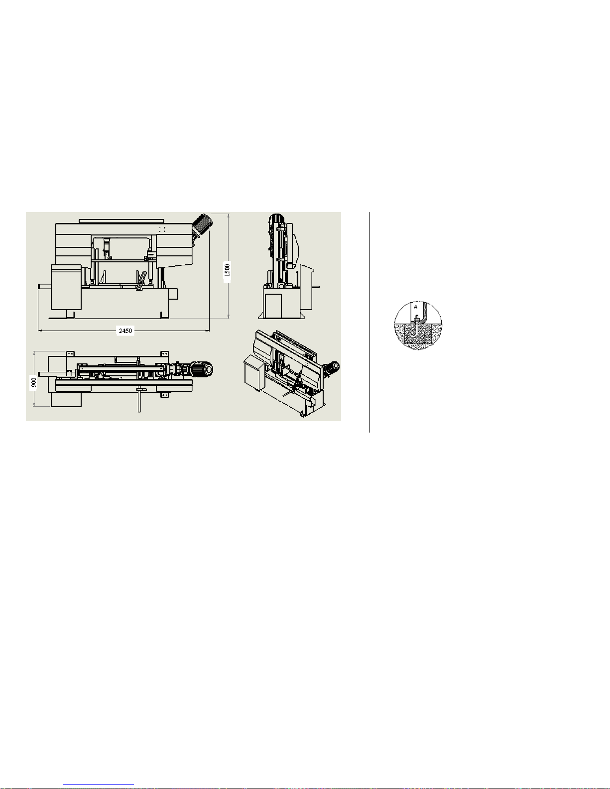
Fixing
Area that machine will be fixed should be flat and bowless. Machine
base should be placed properly , linear and diagonal way . Get the
machine to balance with 4pcs m12 screws that are on the legs, you
should fix it with ø13 steel pins.

Operating instruction
Adjustting the cutting pressure;
İt is used to adjust stroke rate of saw(in other
words to adjust pressure applied to material
by saw) according to the material to be cut.
Gradually its need to reduce the pressure of
saw, when saw becoming blunt. Finaly the
saw should be changed to prevent skewed
cuts
Down feed speed adjustment: adjust
speed according to hardness of
material to be cut. When blade
becomes blunt choose a lower speed
to have a better cut.
Counter: when automatic position, shows
how many pieces will be cut and how many
pieces have been cut. Upper line is preset
the of cuts requered. Lower line shows the
number of cut material. When the counter
reaches the present number, the saw
automatically stops. After this, the reset
button must be presset and made a new
program for next cutting
Emergency stop button:prevents
accidents at unexpecting situations.
Start (ready) button: energises power circuit of the
machine
Start button : start the cutting
Stop button :stops the cutting
Signal button : show sif there is a
problem at the machine.
Coolant button : it is used tol et the coolant
liquid flow.
Feeding material: it is used to feed
forward (1) or backward (2) manuelly,
when the bow is on top (e2 swich
pressed). (controls the feeding motor)
Bow up button: moves the bow up manually
and stops cutting.
Bow down button: moves down the
bow manually.

Manual-automatic select.
Vice pres buton:it is used to press the
matherial
Speed control potmeter : controls the
inverter to adjust the turning speed of blade
Blade tightening button: tighten the
blade.
Area 1 : this shows that the tension of the blade is less than it must be. Adjust the blade
tension.
Area 2 : this shows that the tension of the blade is normal
Area 3 : this shows that the tension of the blade is more than it must be. This may break the
blade. Reduce the tension.
Hydraulic Vice: 25-30 bar
Hydromecanic Blade Tension: min.280 / max.300 bar
Main Pressure:40bar
Hydraulic Blade:90/110 bar

Points To Be Checked On C Series Automatic Machine
A.) Things to be checked on the control panel
1. All equipment necessary for the machine must be placed on the panel as regular.
2. Cable cross-sections and colors must be selected in accordance with the regulation.
3. Cable connections to the equipment must be made properly and each marking must be installed through the cable end.
4. Nomenclature markings must be installed on all equipment .
5. Terminal numbers must be numbered according to the scheme.
6. Current system values used in the system must comply with the fuse requirements.
7. Current motor safety switch values must be set in accordance with the motor.
8. Ground connection must be made with the cover and the keypad board.
9. Potentiometer must be secured with a cable connection using cable ties.
10. Accordance with the keypad on the panel must be secured with bolts.
11. Terminal bridges and signal light bulb must be plugged .
B.) Things to be checked on the machine
1. The control panel on the machine must be secured with the help of scales.
2. Appropriate control switches must be installed on the machine.
3. İf necessary, swich cables must be taken under preservation with the spiral tubes.
4. Door-switch links and switch covers should be the correct assembly must be made with care.
5. All motor connections must be properly connected to the machine operating voltage.
6. The spirals of wire which pass through the machine must be fixed in accordance to the body.
C.) First things to be checked for start
1. Panel cover should be opened and after checking termic flow values, fuses should get ‘on’.
2. All fuses should be taken to "on" position.
3. After closing panel cover the main fuse should be ‘on’ position.
4. The emergency stop button controller panel should be in normal position .
5. Pulley tensioning should be checked and should be sure that the pulley covers are closed.
6. Press the machine readiness green button and the button on the control panel light will turn on the machine.
7. The machine should be located manually and hydraulic movements should be checked.
D.) Things to be checked at semi-automatic position
1. Only when there is material in the vise tightened or just should not start the machine.
2. The machine should not start neither the vice is not clamped nor there is no material.
3. The machine should not start if it is not on top position even there is material and the vices are clamped.
4. The feeding rollers should not be turn on manually if there is not material.
5. The machine should not start up when there is material but it is not clamped;
6. İf all operating conditions are fulfiled (materials exists, vices clamped, machine on top point, the band saw sw) the machine
should start.
7. Approach to the material should be done quickly and then should adjusts the speed of descent that the operator adjusted.
8. Even coolant is in the open position, the coolant should not be flowing till it reached operator down speed.
9. During cutting,
a. When saw up button is pressed the saw should go up till top point and then stop.
b. İf any pulley cover opens, the machine must stop and there should be signal.
c. When emergency stop button is pressed the system must get to stop position and give signal.
d. Clamping pressure must be under constant control.
e. İf the saw blade breaks or there is reduction of tension, the machine must pass to the stop position.
f. After removing the material reached the top spot in the bottom of the machine to automatically erecting vicini point
position and must stop. After finishing cutting the material blade should go down to bottom swich and then rice up to top
point and stop automatically.

E.) Things to be checked at fully-automatic position
1. Hydraulic operations should not be working when the machine is at stop or auto mode.
2. After obtaining the main operating conditions of the machine (tape, cover, emergency stop) at auto mode the machine should
not have ‘no material’ warning signal.
3. You should write part quantity requirements to the counter
4. İf there is not material but the machine is turned on at auto mode, the machine should indicate no material warning signal.
5. The machine should not start up when there is material but it is not clamped;
a. Automatically the blade must go to the upper point switch.
b. Vices should close automatically.
c. Machine should detect firstly the vice swich and then the pressure swich.
d. Wait a while for the detection of the pressure switch. (1-2 sec)
e. After this time the material shoul automatically be fed forward.
f. İf sensor signal is cut during the feeding, the process should stop at that time.
g. The saw must lift up to the height of material.
h. This process should be repeated again, if there is interruption of the sensor signal .
i. Feeding material should go on to the gauge swich.
j. After feeding the material there should be fast approach.
k. With sensor signal stop, the machine should get to the speed that operator adjusted and if it is selected coolant flow should
start.
l. Cutting should keep on till the lower swich point continuously.
m. When the material is cut and lower signal is received , the feeding vice rolls take back the material as the adjusted time
and then the blade goes up.
n. After taking back the material, the blade should go up to the top point.
o. When blade moving above is finished, the machine should inform the counter that cutting is finished and should increase
the value of the counter 1pc.
p. Then feeding should start again and opter operations should go on.
q. All of this should continue until the number of cuts mentioned on the counter..

Sensor Parts
(3)Maximum switch: this switch sets the top point that bandsaw reaches.
(5)Lower limit switch: this limit switch stop the main motor and starts the bow’s upwards movement.
(6)Blade broken pressure switch: this switch stops the main motor when the blade is broken and provides protection of the operator
and the machine from the damages that a broken blade can cause.
(7)Protection cover switches: this switch stops the machine if any cover is open.
(8)Fotocell: this switch starts the main motor when the blade approaches to the material about 30 mm after the bow begins going down
when start button is pressed. And in manual use, this switch stops the movement before the bow crashes to material when the b ow is
going down.
(9) Leaning switch: It provides to cut the material at adjusted length. If the material is feeded at manual control (by shifting material
feeding buton to 1), material’s tip supppreses switch’s shaft which activates the switch. Switch stops the driver motor to cut the material
at desired length. If the material is feeded at automatic control, material will be feeded automatically by driver motor after bow lifts
up.Material’s tip suppresses the Materıal-End Lımıt switch’s shaft which activates the switch . Switch stops the driver motor and turn on
the solenoid valve to start cutting automatically-which means bow’s going down at the same time.
(10)Materıal-End Lımıt Swıtch ( Sq1 ): When the materıal lenght ıs too shoert to be cut, ıt stops the machıne.
1- Wheel Motor
2- Wheel Reductor
3- Maximum Switch
4- Feed Motor
5- Lower Limit Switch
6- Blade Broken Pressure Switch
7- Protection Cover Switches
8- Fotocell
9- Leaning switch
10- Materıal-End Lımıt Swıtch
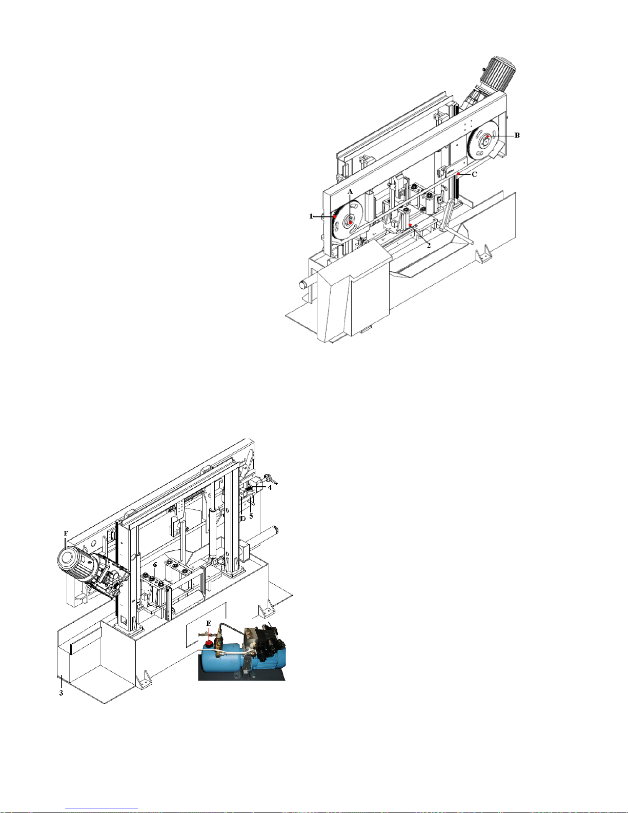
Daily Maintenance
1-Remove The Chips On Wheels
2- Remove The Chips At Shaft And Flat
3- Clean The Chips İn The Boron Oil Tank
Pump Air To Remove The Dirth İn Hoses
4- Manometer Should Be Between 280-300 Bar
5- Clean The Tensioning Slide Flats
6- Check The Chain Tightness And Grease Oil .
Monthly Maintenance
A- Fill Grease Oil From The Hole On The Tentioning Shaft.
B- Check The Tightness Of Wheel Bolts.
C- Check The Chip Brush.
D- Fill Grease Oil From The Hole On The Tensioning Slide
E- Control The Oil Level İn Hydraulic Tank
F-Check The Oil Level On Reductor From Display Incase Of
Decreasing Add Gear Oil (Number 90)

Changing The Hydraulic Oil
Pouring Out The Hydraulic Oil
üLower down until it receives the cutting head.
üRemove hydraulic hose union at head lifting
üPut the removed hydraulic end of the hose into a
container.
üEmpty the oil by pressing head lifting button at control
panel.
After empting the oil, fix the hydraulic hose union to the same
place.
Refilling the hydraulic oil
The hydraulic oil filling
üRemote the bolts of hydraulic drawer, then pull it out.
üOpen the store cover.
üPour 46 numbered iso hydraulic oil into tank. (8lt
capacity.)
üClose the tank cover and move the drawer into the
body
Fasten the screws to the body again with the help of hydraulic
drawer.
Filling Of Coolant
Consisting of a mixture of liquid and water coolant liquid should be used for steel cutting. Coolant should not be used for
cutting casting. Specific periods of time (at least once a month) , coolant should be drained and clean chips. İf amount of coolant is not
enough, add to the tank. (4 liters of tank capacity. Collant mixing ratio 1/10)
Setting New Blade
·First of all both guard flaps and the guards which are on the guide arms have to be open upwards.
·Loosen the blade by the hand level so far that the blade can be easily taken off around the pulleys
·The same way but vic averse, fit and tighten the new blade. There is also possibility to tighten the blade by torque meter.
·Always pay attention to the teeth of the blade’s direction is correct. İf not correct it.
Cutting Speeds
The machine has two pre-selected cutting speeds of 20 and 100 m/sec. Cutting speeds has to be selected according to the grade
and dimensions of the material. İf any vibration and/or noise raises from the blade, change the speed.
·All the details about the cutting of various materials and dimensions are given below

CUTTING RECOMENDATIONS
NOTE:THE CUTTING SPEEDS GIVEN BELOW ARE GUIDELINES ONLY
MATERIAL
MATERIAL DESIGNATION
DIN
MATERIAL
NO
CUTTING SPEED
COOLANT
SPECIAL
LG-SUPER
BI-
METAL
EMULSION
CUTTING OIL
YES
NO
STRUCTUAL STEEL
ST 35 – ST 42
1.0308-
0077
40 - 55
60 - 80
1:10
X
ST 350 – ST 70
1.0052-
0070
30 - 45
50 - 70
1:20
X
HARDENING STEEL
C 10 - C 16
1.0301-
0401
45 - 65
60 - 90
1:10
X
14 NICR 14
1.5752
30 - 40
40 – 50
1:10
X
21 NICR MO 2
1.6523
30 - 45
45 - 55
1:10
X
16 MRCR 5
1,7131
30 - 45
50 - 65
1:10
X
NITRICTED STEEL
(HEAT TREATED)
34 CRAL 6
1,8504
------
20 - 35
1:20
X
34 CR AL NI 7
1,8550
------
20 - 35
1:20
X
FREE CUTTING STEEL
9 S 20
1,0711
45 - 65
70 - 120
1:10
X
HEAT TREATABLE STEEL
C 35 C 45
1,0501-
0503
35 - 55
55 - 75
1:20
X
41 CR 4
1,7035
35 - 35
40 - 60
1:20
X
40 MN 4
1,5038
35 - 45
50 - 65
1:20
X
42 CRMO 4
1,7225
30 - 40
35 - 50
1:20
X
36 NI CR 6
1,5710
30 - 40
50 - 60
1:20
X
24 NI CR 14
1,5754
25 - 35
40 - 60
1:20
X
BALL BEARING STEEL
100 - CR 6
1,3505
25 - 35
50 - 65
1:30
X
105 – CR 4
1,3503
25 - 35
50 - 65
1:30
X
100 – CRMO 6
1,3520
20 - 30
40 - 50
1:30
X
SPRING STEEL
65 SI 7
1,0906
30 - 40
40 - 60
1:30
X
50 CRV 4
1,8159
30 - 40
40 - 60
1:30
X
UNALLOYED TOOL STEEL
C 80 W 1
1,1525
25 - 35
50 - 60
1:30
X
C 125 W 1
1,1560
20 - 30
20 - 35
1:30
X
C 105 W 2
1,1645
25 - 35
40 - 50
1:30
X
ALLOYED TOOL STEEL
105 CR 5
1,2060
30 - 40
50 - 60
1:30
X
X 210 CR 12
1. 2080
------
20 - 35
------
X
X 40 CR MO V 51
1,2344
20 - 30
30 - 40
1:30
X
X 210 CR W 12
1,2436
------
20 - 30
------
X
X 165 CR MP V 12
1,2601
------
20 - 35
1:30
X
56 NICRMOV 7
1,2714
25 - 30
20 - 40
1:30
X
100 CRMO 5
1,2303
20 - 30
35 - 45
1:30
X
X 32 CRMOV 33
1,2365
20 - 30
30 - 45
1:20
X
HIGH SPEED STEEL
S 5-6-2
1,3343
------
25 - 40
1:30
X
S 5-6-2-5
1,3243
------
25 - 40
1:30
X
S 18-0-1
1,3355
------
25 - 40
1:30
X
S 18-1-2-10
1,3265
------
25 - 40
1:30
X
VALVE STEEL
X 45 CRSI 93
1,4718
------
30 - 40
1:20
X
X 45 CRNIW 189
1,4873
------
30 - 40
1:20
X
HIGH TEMPERATURE
STEEL
CRNI 2520
1,4843
------
25 - 40
1:10
X
X 20 CRMOV 211
1,4922
------
25 - 40
1:10
X
X5 NICRTI 2615
1,4980
------
25 - 40
1:10
X
HEAT RESISTING STEEL
X 10 CRAL 7
1,4713
------
20 - 35
1:10
X
X 15 CRNISI 25 / 20
1,4841
------
20 - 35
1:10
X
X 10 CRSI 6
1,4712
------
20 - 35
1:10
X
STAINLESS AND ACID
RESISTING STEEL
X 5 CRNI 189
1,4301
------
25 - 35
1:10
X
X 10 CRNIMPT 1810
1,4571
------
25 - 35
1:10
X
X 10 CR 13
1,4006
------
25 - 35
1:10
X
X 5 CRNIMO 1810
1,4401
------
25 - 35
1:10
X
STEEL CASTING
GS – 38
30 - 40
50 - 60
1:50
X
GS – 60
30 - 40
50 - 60
1:50
X
CAST IRON
GG – 16
30 - 40
40 - 50
------
X
GG – 30
30 - 40
40 - 50
------
X
GTW – 40
30 - 40
40 - 50
------
X
GTS – 65
30 - 40
40 - 50
------
X
HIGH TEMPERATURE
NICKEL ALLOYS
NIMONIC
2,4631
------
15 - 25
1:10
X
HASTELLOY
X 2.4972
------
15 - 25
1:10
X
INCONEL
2,4640
------
15 - 25
1:10
X
ALUMINIUM ALLOYS
AL 99,5
3,0255
80 - 300
100 - 700
1:10
X
ALMG 3
3,3535
80 - 300
100 - 700
1:10
X
BRONZE / TIN BRONZE
CUSN 6
2,1020
50 - 70
70 - 100
1:50
X
G – CUSN 10
2,1050
50 - 70
70 - 100
1:50
X
ALUMINIUM - BRONZE
CUAL 8
2,0920
30 - 45
50 - 70
1:30
X
CUAL 8 FE 38
2,0920,60
30 - 40
40 - 50
1:20
X
RED BRASS
G – CUSN 10 ZN
2,1086,01
30 - 45
70 - 100
1:50
X
G – CUSN 5 ZN PB
2,1096,01
30 - 45
70 - 100
1:50
X
BRASS
CUZN 10
2,0230
80 - 200
100 - 300
1:50
X
CUZN 31 S
2,0490
80 - 200
100 - 300
1:50
X


Table of contents
Other Beka-Mak Saw manuals


Popular Saw manuals by other brands


MK Diamond Products
MK Diamond Products MK-660 SERIES Owner's manual & operating instructions

jcb
jcb JCB-MS-254SB-L Instructions & user's manual

Fox
Fox F28-191 Assembling and operating manual

Pearl
Pearl VX10RSPRO Owner's/operator's manual

Hercules
Hercules H-BW 400 Original operating instructions

Optimum
Optimum OPTIsaw SQ-V13 operating manual