Belden grass valley DENSITE FIO-1901-R Instruction Manual

DENSITÉ series
FIO-1901-R
3G/HD/SD Fiber Optic
to Electrical Converter
Guide to Installation and Operation
M927-0400-101
24 September 2014
3499 Douglas-B.-Floreani
St-Laurent, Québec, Canada H4S 2C6
Tel. 514-333-1772
Fax. 514-333-9828
www.miranda.com
© 2014 Grass Valley A Belden Brand

GUIDE TO INSTALLATION AND OPERATION
FIO-1901-R
Electromagnetic Compatibility
This equipment has been tested for verification of compliance with FCC Part 15, Subpart B requirements for
Class A digital devices.
NOTE: This equipment has been tested and found to comply with the limits for a Class A digital device, pursuant to
part 15 of the FCC Rules. These limits are designed to provide reasonable protection against harmful interference
when the equipment is operated in a commercial environment. This equipment generates, uses, and can radiate
radio frequency energy and, if not installed and used in accordance with the instruction manual, may cause harmful
interference to radio communications. Operation of this equipment in a residential area is likely to cause harmful
interference in which case the user will be required to correct the interference at his own expense.
This equipment has been tested and found to comply with the requirements of the EMC directive
2004/108/CE:
•EN 55022 Class A radiated and conducted emissions
•EN 55024 Immunity of Information Technology Equipment
•EN 61000-3-2 Harmonic current injection
•EN 61000-3-3 Limitation of voltage changes, voltage fluctuations and flicker
•EN 61000-4-2 Electrostatic discharge immunity
•EN 61000-4-3 Radiated electromagnetic field immunity – radio frequencies
•EN 61000-4-5 Surge immunity
•EN 61000-4-11 Voltage dips, short interruptions and voltage variations immunity
How to contact us:
For technical assistance, please contact the Grass Valley Technical support center nearest you:
Americas
9:00 am – 9:00 pm EST
Tel: +1 800 224 7882
Fax: +1 514 335 1614
support@miranda.com
Asia
9:30 am – 6:00 pm GMT+8
Tel: +852 2539 6987
Fax: +852 2539 0804
asiatech@miranda.com
Europe, UK, Middle East, Africa
9:00 am – 6:00 pm GMT
Tel: +44 118 952 3444
Fax: +44 118 952 3401
eurotech@miranda.com
Emergency After Hours
(worldwide)
Tel: 1 800 224 7882
-or-
Tel: 1 514 333 1772
and choose menu
option 2
France
9:00 am – 5:00 pm GMT+1
Tel: +33 1 55 86 87 88
Fax: +33 1 55 86 00 29
eurotech@miranda.com
China
9:30 am – 6:00 pm GMT+8
Tel: +86 10 5873 1814
asiatech@miranda.com
(Playout Automation Only)
9:00 am – 5:30 pm GMT
Tel: +44 8705 004 350
Fax: +44 8705 004 333
automationsupport@miranda.com
Visit our web site at www.grassvalley.com

GUIDE TO INSTALLATION AND OPERATION
FIO-1901-R
Table of Contents
1FIO-1901-R 3G/HD/SD Fiber Optic to Electrical Converter....................................................1
1.1 Introduction ......................................................................................................................................... 1
1.2 Features.............................................................................................................................................. 1
1.3 Block Diagram..................................................................................................................................... 2
1.4 Front Card-edge Interface................................................................................................................... 2
2Installation................................................................................................................................3
2.1 Installation in a Densité-2 frame ......................................................................................................... 3
2.2 Installation in a Densité-3 Frame........................................................................................................ 4
2.3 SFP Modules....................................................................................................................................... 6
3Operation..................................................................................................................................7
3.1 Card-Edge Status LED ....................................................................................................................... 7
3.2 Local control using the Densité frame control panel........................................................................... 7
3.2.1 Overview................................................................................................................................ 7
3.2.2 Menu for local control............................................................................................................. 8
3.2.3 Detailed Operating Procedure ............................................................................................... 8
3.2.3.1 Reclocker............................................................................................................... 9
3.2.3.2 User Presets.......................................................................................................... 9
3.2.3.3 Configure Alarms................................................................................................... 9
3.3 Remote control using iControl........................................................................................................... 10
3.3.1 The iControl graphic interface window................................................................................. 10
3.3.2 The Status panel.................................................................................................................. 12
3.3.3 The Reclocker panel............................................................................................................ 12
3.3.4 The Factory/Presets panel................................................................................................... 13
3.3.5 The Alarm Config panel....................................................................................................... 13
3.3.6 The Info panel...................................................................................................................... 16
4Specifications.........................................................................................................................18
ANNEX 1 – FIO-1901-R User Interface (local menu structure)..................................................19
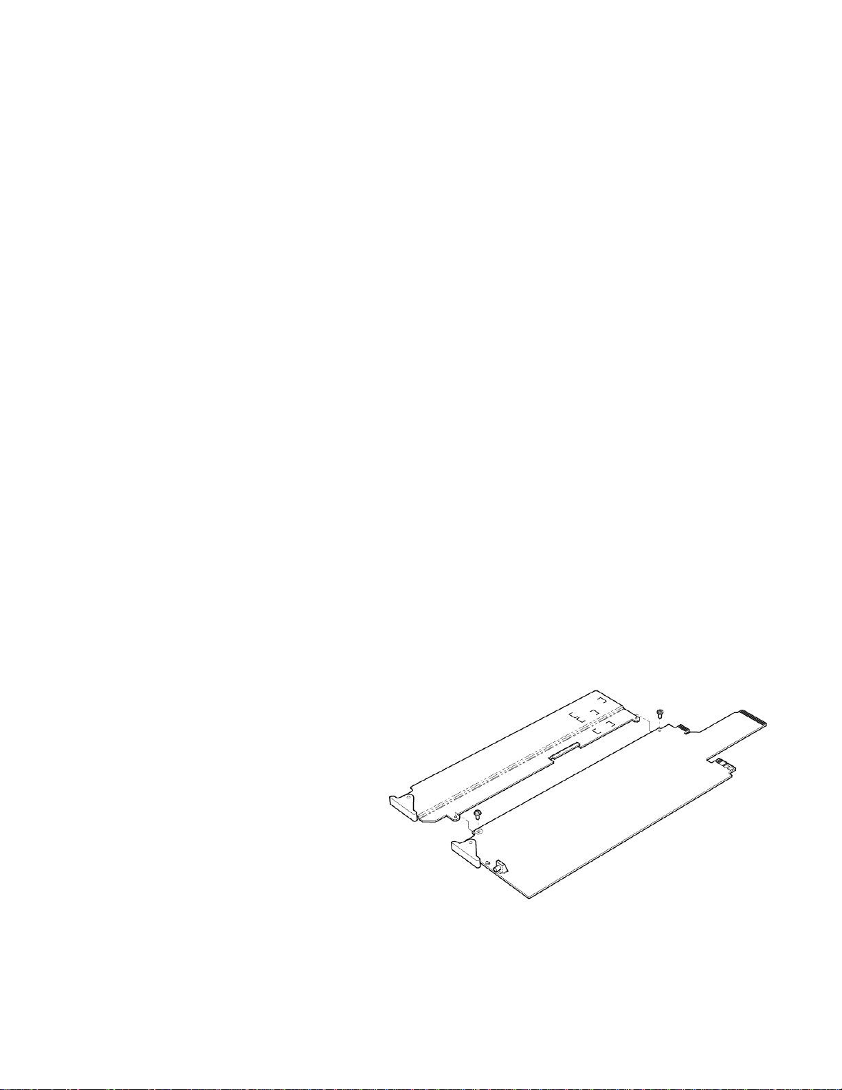
ANNEX 2 – Installing the Optical Interface.................................................................................20

GUIDE TO INSTALLATION AND OPERATION
FIO-1901-R

GUIDE TO INSTALLATION AND OPERATION
FIO-1901-R | 1
1 FIO-1901-R 3G/HD/SD Fiber Optic to Electrical Converter
1.1 Introduction
The FIO-1901 series are flexible serial digital video To/From Fiber Optic converters for the Densité frames. The FIO-
1901 series are designed for SD, HD and 3G serial video as well as compressed bit-streams (DVB-ASI). The series
supports any data rate within the range of 50 Mbps to 2.97 Gbps and provides a reclocked serial digital video from
270Mbps to 2.97 Gbps. The FIO-1901 series offer five different configurations: Single or dual fiber Tx, single or dual
fiber Rx and a bi-directional fiber Rx/Tx. The series is based on SFP modules that provide easy product maintenance
and flexibility when multiple wavelengths are needed (as for CWDM). The SFP Modules are also hot-swappable.
The FIO-1901 can be installed in the same chassis as a series of interface modules, providing a wide variety of video,
audio and data conversion and multiplexing functions.
The FIO-1901-R version incorporates a single optical receiver and provides a pair of electrical outputs.
1.2 Features
•Supports any serial data rate from 19.4 Mbps (ATSC) to 2.97 Gbps (3G SDI)
•Reclocked serial digital video for 270 Mbps, 1.49 Gbps, and 2.97 Gbps
•Provides a unidirectional interface between fiber optic and serial digital
•Supports Multiple wavelengths from the standard 1310 nm, 1550 nm to multiple CWDM wavelengths
•Ideal for long video run with “Hum” immunity
•Presence/loss of signal alarm – iControl, on-board LED and Densité Control Panel
•SFP Optical power monitoring and report
•Internal SFP temperature alarms on the iControl interface and on the Densité Control Panel
•SFP Module type detections and report mismatch
•Remote monitoring and control
•Convenient front loading design
•The cards and the SFP modules are fully hot swappable

GUIDE TO INSTALLATION AND OPERATION
2| FIO-1901-R
1.3 Block Diagram
The following block diagram shows the functionality of the FIO-1901-R.
Figure 1-1 Functional block diagram of the FIO-1901-R
1.4 Front Card-edge Interface
The front card-edge of the FIO-1901-R incorporates two elements:
•Status LED (see section 3.1)
•Select Button (see section 3.2)
Figure
1-2 Front card-edge layout
Select
Status
FIO-1901-R
Status LED
Select Button

GUIDE TO INSTALLATION AND OPERATION
FIO-1901-R | 3
2 Installation
Miranda Densité-series cards are each associated with a rear connector panel, which must be installed in the Densité
frame before the card can be inserted.
The FIO-1901-R card is sized to fit into Miranda’s Densité-2 frame. One rear connector panel is available to fit the
Densité 2 frame:
•FIO-1901-R-SRP – 1 fiber input and 2 electrical outputs
See section 2.1 below for installation instructions.
With the use of available adapters, the FIO-1901-R and its rear panel can also be installed in a Densité-3 frame. See
section 2.2 below for details.
2.1 Installation in a Densité-2 frame
All cards and rear panels can be installed with the frame power on. The card has connectors which plug into a mid-
frame mother board for distribution of power and for connection to the controller card, and a second connector which
plugs directly into the rear connector panel for input and output.
The rear connector panel must be installed with the card out of the frame.
- To remove an existing card from the slot, tilt up the swivel handle on the front of the card to lever the connectors
apart, then use the handle to pull the card straight out of the slot.
Installing the connector panel:
1. If a card is installed in the slot whose rear panel is being changed, remove it as described above.
2. Remove the existing panel (either blank or belonging to an existing card that is being changed) by releasing the
captive screw(s) at the bottom.
3. Position the new panel and secure it in place with the captive screw(s) at the bottom.
Densité-2 frame – rear panel installation

GUIDE TO INSTALLATION AND OPERATION
4| FIO-1901-R
Installing the card
Once a matching rear connector panel has been installed, install the FIO-1901-R card as follows:
1. Open the front panel of the frame.
2. Slide the FIO-1901-R card into the slot with the swivel handle at the top, and push gently on the handle to seat
the connectors.
3. Close the front panel of the frame.
2.2 Installation in a Densité-3 Frame
All cards and rear panels can be installed with the frame power on. The card has connectors which plug into a mid-
frame mother board for distribution of power and for connection to the controller card, and a second connector which
plugs directly into the rear connector panel for input and output.
The rear connector panel must be installed with the card out of the frame.
•To remove an existing card from the slot, tilt up the swivel handle on the front of the card to lever the connectors
apart, then use the handle to pull the card straight out of the slot.
The Densité-3 frame supports many Miranda Densité-2 series cards, including the FIO-1901-R. Should you wish to
install the FIO-1901-R card in your Densité-3 frame, you will need an adapter for the card as well as an adapter for
the rear panel. These adapters extend the height of the Densité-2 devices so that they will fit into the slots of the 3 RU
Densité-3 frame.
Card adapter:
There are 3 different types of adapters available, depending on the Densité 2 card geometry, so be sure to order the
adapter designed to fit the FIO-1901-R card:
Densité 3 – EXT B
Install the adapter on the FIO-1901-R as follows:
1. Fit the top edge of the card into the holding slot
along the bottom edge of the adapter.
2. Align the holes in the top of the card with the
holes on the adapter, and secure them together
with the two provided screws and lock washers,
as shown in the figure.

GUIDE TO INSTALLATION AND OPERATION
FIO-1901-R | 5
Rear adapter:
The FIO-1901-R-SRP rear panel requires the following adapter for use in a Densité-3 frame:
DENSITE SRP-3RU
Installing the adapter and connector panel
Install the adapter and the rear panel as follows:
1. Position the adapter at the top of the empty
slot on the rear of the frame.
2. Use the captive screw in the adapter to
fasten it securely in position.
3. Slip the top of the rear panel into the slot at
the bottom of the adapter, and secure it to the
frame using the captive screw at the bottom of
the panel.
Installing the card
Once the rear connector panel has been installed,
insert the FIO-1901-R card with attached adapter as
follows:
1. Open the front panel of the Densité-3 frame.
2. Slide the FIO-1901-R card into the slot with
the swivel handle at the top, and push gently
on the handle to seat the connectors.
3. Close the front panel of the frame.

GUIDE TO INSTALLATION AND OPERATION
6| FIO-1901-R
The FIO-1901-R-SRP single-slot rear panel, mounted in a Densité 2 or Densité 3 frame, incorporates these
connectors:
•One socket for inserting a fiber treceiver SFP module – see the list of supported modules below.
•One BNC connector for the 3G/HD/SD SDI input
•One BNC connector for the 3G/HD/SD SDI output
2.3 SFP Modules
The FIO-1901-R supports the following SFP optical interface module:
FIO-1901-RT Model # Description of associated SFP module
FIO-1901-R-LC Single fiber 3G/HD/SD Rx cartridge – LC/PC connectors
See ANNEX 2 – Installing the Optical Interface, beginning on page 20, for instructions on installing and removing SFP
modules.
Figure 2.1 FIO-1901-R-SRP Rear Panell

GUIDE TO INSTALLATION AND OPERATION
FIO-1901-R | 7
3 Operation
3.1 Card-Edge Status LED
The status monitor LED is located on the front card-edge of the FIO-1901-R, and is visible through the front access
door of the DENSITÉ frame. This multi-color LED indicates the status of the FIO-1901-R by color, and by
flashing/steady illumination.
The chart shows how the various error conditions that can be flagged on the FIO-1901-R affect the LED status.
•If a cell is gray, the error condition cannot cause the LED to assume that status
•If more than one LED status is possible for a particular error condition, the status is configurable.
See Sections 3.2.3.3 and 3.3.5 for details.
•The factory default status is shown by a
The LED will always show the most severe detected error status that it is configured to display, and in the chart error
severity increases from left to right, with green representing no error/disabled, and flashing red the most severe error.
Card-edge LED Status
Error Condition
Green
Yellow
Red
Flashing
Yellow
Flashing
Red
No errors
No input signal presence
No lock on input signal
No SFP module present
Card / Rear panel / SFP module mismatch
No Rear
SFP Temperature
Card is selected for local control
Firmware Update
If the LED is Flashing Yellow, it means that the card is selected for local control using the Densité frame’s control
panel, or that the card is booting up. See Section 3.2 for details.
3.2 Local control using the Densité frame control panel
3.2.1 Overview
Push the SELECT button on the FIO-1901-R card edge (see Section 1.4) to assign the local control panel to operate
the FIO-1901-R. Use the control panel buttons to navigate through the menu, as described below.
All of the cards installed in a Densité frame are connected to the frame’s controller card, which handles all interaction
between the cards and the outside world. There are no operating controls located on the cards themselves. The
controller supports remote operation via its Ethernet ports, and local operation using its integrated control panel.

GUIDE TO INSTALLATION AND OPERATION
8| FIO-1901-R
The local control panel is fastened to the controller card
by a hinged connector, and when installed is located in
the front center of the frame, positioned in front of the
power supplies. The panel consists of a display unit
capable of displaying two lines of text, each 16
characters in length, and five pushbuttons.
The panel is assigned to operate any card in the frame
by pushing the SELECT button on the front edge of that
card.
•Pushing the CONTROLLER button on the
control panel selects the Controller card itself.
•The STATUS LED on the selected card flashes
yellow.
The local control panel displays a menu that can be navigated using the four pushbuttons located beside the display.
The functionality of the pushbuttons is as follows:
[+] [–] Used for menu navigation and value modification
[SELECT] Gives access to the next menu level. When a parameter value is shown, pushing this button once
enables modification of the value using the [+] and [–] buttons; a second push confirms the new value
[ESC] Cancels the effect of parameter value changes that have not been confirmed; pushing [ESC] causes the
parameter to revert to its former value.
Pushing [ESC] moves the user back up to the previous menu level. At the main menu, [ESC] does not
exit the menu system. To exit, re-push the [SELECT] button for the card being controlled.
If no controls are operated for 30 seconds, the controller reverts to its normal standby status, and the selected card’s
STATUS LED reverts to its normal operating mode. If a parameter was changed on the card but not submitted
(SELECT was not pressed) and the 30 second timeout occurs, the parameters will be confirmed as if the SELECT key
had been pressed.
3.2.2 Menu for local control
The FIO-1901-R has operating parameters which may be adjusted locally at the controller card interface.
•Press the SELECT button on the FIO-1901-R front card edge to assign the Densité frame’s local control panel
to the FIO-1901-R
•Use the keys on the local control panel to step through the displayed menu to configure and adjust the FIO-
1901-R
•The first items to appear on the local display are card status messages, followed by operating controls.
The complete menu structure is shown in the Annex to this document, beginning on page 19.
3.2.3 Detailed Operating Procedure
The basic operating characteristics of the FIO-1901-R can be adjusted using the local control panel.
•Refer to the menu on page 19 for help in accessing the indicated items.
•In all sets of optional values for a parameter, the underlined value is the default value.
Figure
3-1 Densité Frame local control panel

GUIDE TO INSTALLATION AND OPERATION
FIO-1901-R | 9
3.2.3.1 Reclocker
Enable reclocking of the video data stream arriving at the optical receiver. The reclocker operates at the video
standard rates of SD (270Mbps), HD (1.49Gbp), and 3G (2.97Gbps).
Optical Rx: [ON, BYPASS]
3.2.3.2 User Presets
The FIO-1901-R has five data storage registers that can save the device configuration. Each register can be saved
independently by the user, and the device can be reconfigured from the contents of any of the registers by the user.
LOAD: [USER1, USER2, USER3, USER4, USER5] Load the contents of the preset into the FIO-1901-R
SAVE: [USER1, USER2, USER3, USER4, USER5] Save the configuration of the FIO-1901-R into the preset
3.2.3.3 Configure Alarms
For each of the configurable alarms listed in the menu:
OPT Rx NO LOCK (Optical receiver not locked)
OPT Rx NO SIGNAL (Optical receiver no signal)
OPT Rx PWR WARN (Optical receiver power warning)
OPT Rx PWR ERR (Optical receiver power error)
SFP TEMPERATURE (temperature on the SFP module)
R/SFP MISMATCH (any mismatch between the card type / rear panel type / installed SFP module type)
NO SFP (no SFP module installed)
Select the way in which it will be displayed on the card-edge Status LED.
Alarm level: [GREEN, YELLOW, RED, FLASH RED]
For each alarm, select whether it will be reported on the GPI output of the frame controller.
Alarm report: [NONE, GPI]

GUIDE TO INSTALLATION AND OPERATION
10 | FIO-1901-R
3.3 Remote control using iControl
The operation of the FIO-1901-R may be controlled using Miranda’s iControl system.
•This manual describes the control panels associated with the FIO-1901-R and their use.
•Please consult the iControl User’s Guide for information about setting up and operating iControl.
In iControl Navigator or iControl Websites, double-click on the FIO-1901-R icon to open the control panel.
3.3.1 The iControl graphic interface window
The basic window structure for the FIO-1901-R is shown in figure 3.2. The window identification line gives the card
type and the slot number where the card is installed in its Densité frame.
There are three main sections in the window itself, identified in figure 3.2:
1. The top section displays icons on the left. These icons report the
status of some parameters associated with this FIO-1901-R. Figure 3.3
shows the two icons that appear.
Move the mouse over an icon and a status message appears below the
icon providing additional information.
If there is an error, the error status message appears in the message
area without mouse-over.
•If there are multiple errors, the error messages cycle
•The icon whose status or error message is shown is highlighted
with a mauve background
Icon # 1 2
1
2
3
3
Figure
3-2 FIO-1901-R iControl graphic interface window
Figure 3-3 iControl Status Icons

GUIDE TO INSTALLATION AND OPERATION
FIO-1901-R | 11
The table below lists the various status icons that can appear, and how they are to be interpreted.
•In cases where there is more than one possible interpretation, read the error message in the iControl window to
see which applies.
Table – iControl Status Icon interpretation
Icon #1 – Manual Card Configuration
(green)
Remote card control activated. The iControl interface can be used to operate the card
(yellow)
Local card control active, The card is being controlled using the Densité frame control
panel, as described in section 3.2. Any changes made using the iControl interface will have
no effect on the card.
Icon #2 – In A status
(green)
Signal detected and valid.
(yellow)
No lock
(red)
No signal
No rear
Section 2. The left portion of the window contains access buttons for all the parameter groups, which become
highlighted when they are selected; the main panel (3) then displays the group’s set of parameters. Each of the
groups is described in detail below.
Section 3. The main panel contains all the parameters specific to the group selected.
Each of the panels associated with the groups accessed from the buttons in Section 2, and shown in Section 3, is
described individually in the following sections.

GUIDE TO INSTALLATION AND OPERATION
12 | FIO-1901-R
3.3.2 The Status panel
This panel reports the status of this FIO-1901-R card, its
rear panel, its SFP module, and the signals arriving at the
optical input on the rear panel.
OPTICAL RX
•Shows the incoming data rate when a signal is
successfully received (green icons)
•Identifies No Lock (yellow icon) or No Signal (red
icon) conditions
Rear Type – the data box identifies the rear panel installed
in the Densité frame for this FIO-1901-R.
Rear mismatch – the icon is green when a compatible rear
panel is installed and red when an incompatible rear panel is
installed.
SFP - the data box identifies the SFP module installed in the
rear panel for this FIO-1901-R.
SFP mismatch – the icon is green when a compatible SFP
module is installed and red when an incompatible SFP
module is installed.
SFP Info – the data boxes in this section give information
about the SFP module itself, and measured data about the
operating status of the receiver RX.
3.3.3 The Reclocker panel
Use the radio buttons to enable reclocking of the video data
stream on the optical input.
The reclocker operates at the video standard rates of
SD (270 Mbps), HD (1.485 Gbps), and 3G (2.97 Gbps):
ON – reclock the data before passing it to the output
BYPASS – pass the data stream through without reclocking
Figure
3-4 Status panel
Figure
3-5 Reclocker panel

GUIDE TO INSTALLATION AND OPERATION
FIO-1901-R | 13
3.3.4 The Factory/Presets panel
Click the Load Factory button to reset all parameters on this
FIO-1901-R card to factory default values.
•The factory default values are shown underlined in the
menu found in the Annex to this document, beginning
on page 19.
User Presets
The FIO-1901-R has memory registers which can hold up to
5 user-defined parameter settings.
Select any one of the five presets using the pull-down list.
The name of the currently-selected User Preset is shown on
the name bar.
Click Load to load the contents of the selected User Preset
into the FIO-1901-R. All parameter settings and values will
be replaced by the contents of the selected User Preset.
Click Save to store the current parameter settings and
values from the FIO-1901-R into the selected User Preset.
The existing contents of the preset will be overwritten
without asking for confirmation.
3.3.5 The Alarm Config panel
This panel allows the alarm
reporting of the FIO-1901-R
to be configured.
Click on the Alarm Config
button to open the Alarm
Configuration window.
The Alarm Configuration
window is organized in
columns
Status/Name
This contains an
expandable tree listing all
the alarms reported by this
FIO-1901-R card.
•Each alarm name
includes an icon that
shows its current
status
Figure
3-6 Factory / Presets panel
Figure
3-7 Alarm Configuration window

GUIDE TO INSTALLATION AND OPERATION
14 | FIO-1901-R
The Card LED, Overall alarm and GSM contribution columns contain pulldown lists that allow the level of
contribution of each individual alarm to the alarm named in the column heading to be set.
Click on the alarm icon to see the available levels; then click on one to select it
Card LED
This column allows configuration of the contribution of each individual alarm to the status reported by the Status
LED on the front edge of the FIO-1901-R card, visible through the front door of the Densité frame.
Overall Alarm
This column allows configuration of the contribution of each individual alarm to the Overall Alarm associated with
this card. The Overall Alarm is shown in the upper left corner of the iControl panel, and also appears at the bottom
of the Status/Name column.
GSM Contribution
This column allows configuration of the contribution of each individual alarm to the GSM Alarm Status associated
with this card. GSM is a dynamic register of all iControl system alarms, and is also an alarm provider for external
applications. The possible values for this contribution are related to the Overall alarm contribution:
•If the Overall alarm contribution is selected as Disabled, the GSM alarm contribution can be set to any available
value
•If the Overall alarm contribution is selected as any level other than disabled, the GSM contribution is forced to
follow the Overall Alarm.
Levels associated with these alarms:
The pulldown lists may contain some or all of the following options:
The alarm makes no contribution (black icon)
The alarm is of minor importance (yellow icon)
The alarm is of major importance (orange icon)
The alarm is of critical importance (red icon)
The alarm exists but has no effect (used for text and composite alarms)
Shortcut: if you click on one of the “Set All” boxes in the Card LED, Overall Alarm or GSM Contribution columns,
you will open a pulldown that lets you assign a level to all alarms in that section of the column simultaneously.
Log Events
iControl maintains a log of alarm events associated with the card. The log is useful for troubleshooting and identifying
event sequences. Click in the checkbox to enable logging of alarm events for each individual alarm.
At the bottom of the window are several other controls.
Overall alarm and GSM contribution follow card LED
Click in the checkbox to force the Overall alarm and GSM contribution to be identical to the Card LED status
•All Overall alarms and GSM contributions for which there is a Card LED alarm will be forced to match the Card
LED alarm
•All Overall Alarms and GSM contributions for which there is no Card LED alarm will be forced to Disabled

GUIDE TO INSTALLATION AND OPERATION
FIO-1901-R | 15
A warning box will open allowing you to confirm the action,
since it will result in changes to the configuration and there
is no undo function.
Copy to other cards
Click this button to open a panel that allows the
alarm configuration set for this card to be copied
into another FIO-1901-R card.
•Select one or more destination cards from
the list in the window by clicking in the
checkboxes, or all of them by clicking in the
All checkbox
Get alarm keys
Click this button to open a save dialog where you
can save a file containing a list of all alarms on this
card and their current values, along with an Alarm
Key for each. The alarm keys are useful for
system integration and troubleshooting.
•The file is saved in .csv format
Figure
3-8 Warning for Follow LED change
Figure
3-10 Save dialog for Get Alarm Keys
Figure
3-9 Copy to Other Cards

GUIDE TO INSTALLATION AND OPERATION
16 | FIO-1901-R
OK, Apply, Cancel
•OK accepts the settings and closes the window once the card confirms that there are no errors.
•Apply accepts the settings, but leaves the window open
•Cancel closes the window without applying any changes, and leaves the previous settings intact.
3.3.6 The Info panel
When the FIO-1901-R is included in an iControl
environment, certain information about the card should be
available to the iControl system. The user can enter labels
and comments that will make this card easy to identify in a
complex setup. This information is entered into data boxes
in this panel.
Label: type the label that is shown for this FIO-1901-
R when it appears in iControl applications
Short Label type the short-form label that iControl uses in
some cases (8 characters)
Source ID type a descriptive name for this FIO-1901-R
Comments: type any desired text
The remaining data boxes show manufacturing information
about this card.
Three buttons in the panel give access to other information.
•Details…: Reports the Firmware version, service version,
and panel version for this card
•Advanced…: Shows the Miranda LongID for this card. The
Miranda LongID is the address of this FIO-1901-R in the
iControl network.
Figure
3-11 Info panel
Figure
3-12 Details window
Figure
3-13 Advanced window
Table of contents
Other Belden Media Converter manuals

Belden
Belden Grass Valley Rattler 4 User manual

Belden
Belden Grass Valley K-Frame Supplement

Belden
Belden Grass Valley Kayenne K-Frame Supplement

Belden
Belden thinklogical Velocitykvm-4 User manual

Belden
Belden Grass Valley Kayenne How to use

Belden
Belden GRASS VALLEY XIP-3901 User manual

Belden
Belden GRASS VALLEY KUDOSPRO UHD 1100 User manual

Belden
Belden Grass Valley Kayenne K-Frame User manual

Belden
Belden Grass Valley LUMO User manual

Belden
Belden Grass Valley EC9535 User manual