Belden GRASS VALLEY XIP-3901 User manual

XIP-3901
Agile SDI/IP Processing Platform
User Manual
13-03065-010-AC-M00
2018-11-23

INSTALLATION AND OPERATION GUIDE
XIP-3901
Document History
Document Number
Publication Date
Notes
13-03065-010-AA-M00
2018-06-14
Initial release
13-03065-010-AB-M00
2018-09-25
External reference support for XIP-3901-UC 1.1
XIP-3901-DC 1.0 release
Agile processing platform manager for XIP-3901-UC 1.1 and XIP-
3901-DC 1.0
13-03065-010-AC-M00
2018-11-23
XIP-3901-FS 1.0 release
Copyright and Trademark Notice
Copyright © 2018, Grass Valley Canada. All rights reserved.
Belden, Belden Sending All The Right Signals, and the Belden logo are trademarks or registered trademarks of
Belden Inc. or its affiliated companies in the United States and other jurisdictions. Grass Valley, Miranda, XIP-
3901, iControl, and Densité are trademarks or registered trademarks of Grass Valley Canada. Belden Inc., Grass
Valley Canada, and other parties may also have trademark rights in other terms used herein.
Terms and Conditions
Please read the following terms and conditions carefully. By using the XIP-3901 documentation, you agree to the
following terms and conditions.
Grass Valley hereby grants permission and license to owners of XIP-3901 to use their product manuals for their
own internal business use. Manuals for Grass Valley products may not be reproduced or transmitted in any form
or by any means, electronic or mechanical, including photocopying and recording, for any purpose unless
specifically authorized in writing by Grass Valley.
A Grass Valley manual may have been revised to reflect changes made to the product during its manufacturing
life. Thus, different versions of a manual may exist for any given product. Care should be taken to ensure that one
obtains the proper manual version for a specific product serial number.
Information in this document is subject to change without notice and does not represent a commitment on the part
of Grass Valley.
Warranty information is available in the Support section of the Grass Valley website (www.grassvalley.com).
Electrostatic Discharge (ESD) Protection
Electrostatic discharge occurs when electronic components are improperly handled and can result in
intermittent failure or complete damage, adversely affecting an electrical circuit. When you remove and
replace any card from a frame, always follow ESD-prevention procedures:
Ensure that the frame is electrically connected to earth ground through the power cord or any other means if
available.
Wear an ESD wrist strap, ensuring that it makes good skin contact. Connect the grounding clip to an
unpainted surface of the chassis frame to safely ground unwanted ESD voltages. If no wrist strap is available,
ground yourself by touching the unpainted metal part of the chassis.

INSTALLATION AND OPERATION GUIDE
XIP-3901
For safety, periodically check the resistance value of the antistatic strap, which should be between 1 and
10 megohms.
When temporarily storing a card, make sure it is placed in an ESD bag.
Cards in an earth-grounded metal frame or casing do not require any special ESD protection.
Recycling
Visit www.grassvalley.com for recycling information.
Certification and Compliance
Safety of Laser Modules
This equipment incorporates modules containing Class 1 lasers. These modules are certified by the
manufacturer to comply with:
IEC/EN 60825-1 Safety of laser products
IEC 60950-1 Safety of information technology equipment
Restriction on Hazardous Substances (RoHS)
XIP-3901
部件名称 Part name
有毒有害物质或元素 (Toxic or Hazardous Substances and Elements)
铅(Pb)
汞(Hg)
镉(Cd)
六价铬
(Cr6)
多溴联苯
(PBB)
多溴二苯
(PBDE)
电缆及电缆组件 Cables and Cable Assemblies
O
O
O
O
O
O
电路模块 Circuit Modules
X
O
O
O
O
O
组装风扇 Fan Assemblies
X
O
O
O
O
O
XIP-3901-3+DRP
部件名称 Part name
有毒有害物质或元素 (Toxic or Hazardous Substances and Elements)
铅(Pb)
汞(Hg)
镉(Cd)
六价铬
(Cr6)
多溴联苯
(PBB)
多溴二苯
(PBDE)
电路模块 Circuit Modules
X
O
O
O
O
O
O: 表示该有毒有害物质在该部件所有均质材料中的含量均在SJ/T 11363-2006规定的限量要求以下。
O: Indicates that this toxic or hazardous substance contained in all of the homogeneous materials for this part is below the
limit requirement in SJ/T11363-2006.
X: 表示该有毒有害物质至少在该部件的某一均质材料中的含量超出SJ/T 11363-2006规定的限量要求。
X: Indicates that this toxic or hazardous substance contained in at least one of the homogeneous materials for this part is
above the limit requirement in SJ/T11363-2006.
技术条款解释:
此声明所依据之数据由Grass Valley环境管理部门向我们的部件供应商获取。Grass Valley 公司相信此信息的正确性,但由于
数据来源于公司外部,我们无法保证它的完整和准确。所有这些特性可能在未获通知的情况下更改。
Technical explanations:
This statement is based on the information provided by our suppliers and collected through Grass Valley’s environmental
management system. Grass Valley believes this environmental information to be correct but cannot guarantee its
completeness or accuracy as it is based on data received from sources outside our company. All specifications are subject
to change without notice.

INSTALLATION AND OPERATION GUIDE
XIP-3901
Electromagnetic Compatibility
This equipment has been tested for compliance with FCC Part 15, Subpart B requirements for Class A
digital devices.
NOTE: This equipment has been tested and found to comply with the limits for a Class A digital device,
pursuant to Part 15 of the FCC Rules. These limits are designed to provide reasonable protection against
harmful interference when the equipment is operated in a commercial environment. This equipment generates,
uses, and can radiate radio frequency energy and, if not installed and used in accordance with the instruction
manual, may cause harmful interference to radio communications. Operation of this equipment in a residential
area is likely to cause harmful interference, in which case the user will be required to correct the interference at
his own expense.
This equipment has been tested and found to comply with the requirements of the EMC directive
2004/108/CE:
EN 55022 Class A radiated and conducted emissions
EN 61000-3-2 Harmonic current emission limits
EN 61000-3-3 Voltage fluctuations and flicker limitations
EN 61000-4-2 Electrostatic discharge immunity
EN 61000-4-3 Radiated electromagnetic field immunity –RF
EN 61000-4-4 EFT immunity
EN 61000-4-5 Surge immunity
EN 61000-4-6 Conducted immunity
EN 61000-4-8 EMP immunity
EN 61000-4-11 Voltage dips, short interruptions and voltage variations immunity

INSTALLATION AND OPERATION GUIDE
XIP-3901
Table of Contents
1Introduction to the XIP-3901 Agile SDI/IP Processing Platform............................................1
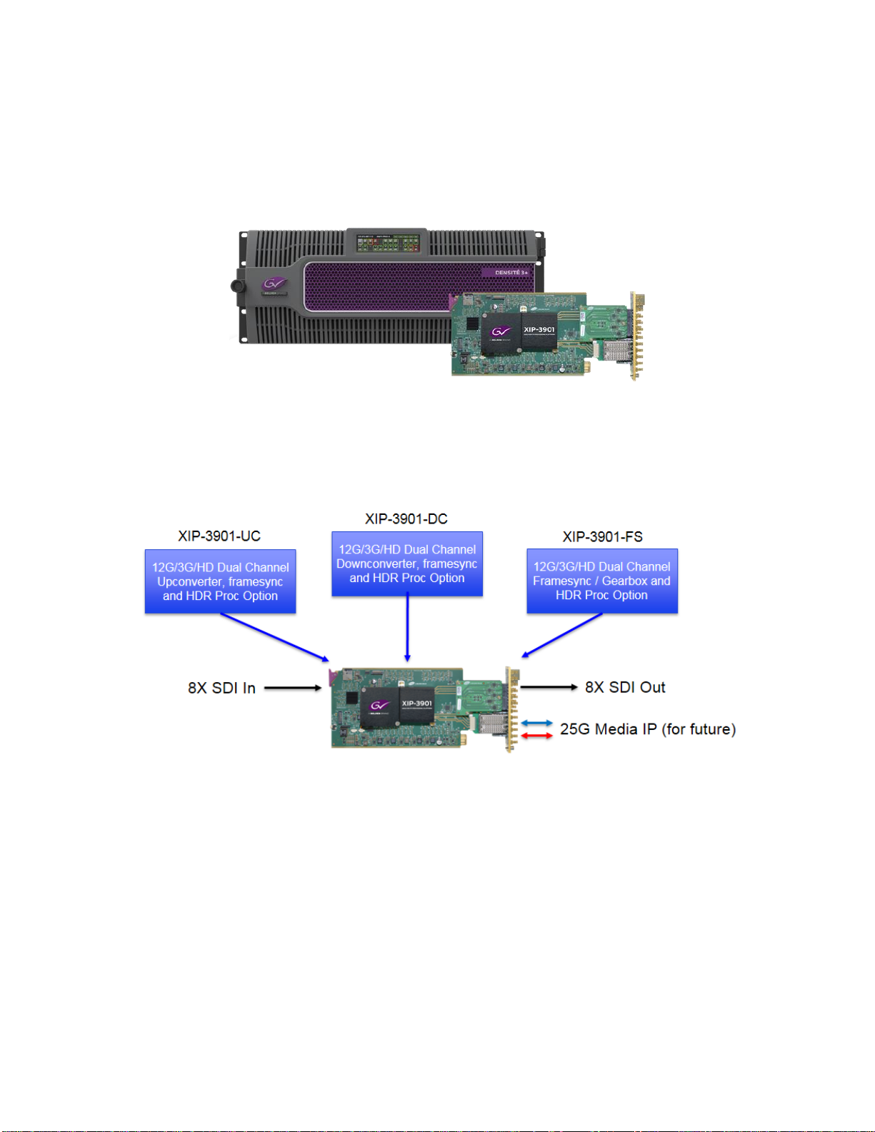
2XIP-3901 Applications..............................................................................................................2
Key Features....................................................................................................................................... 22.1
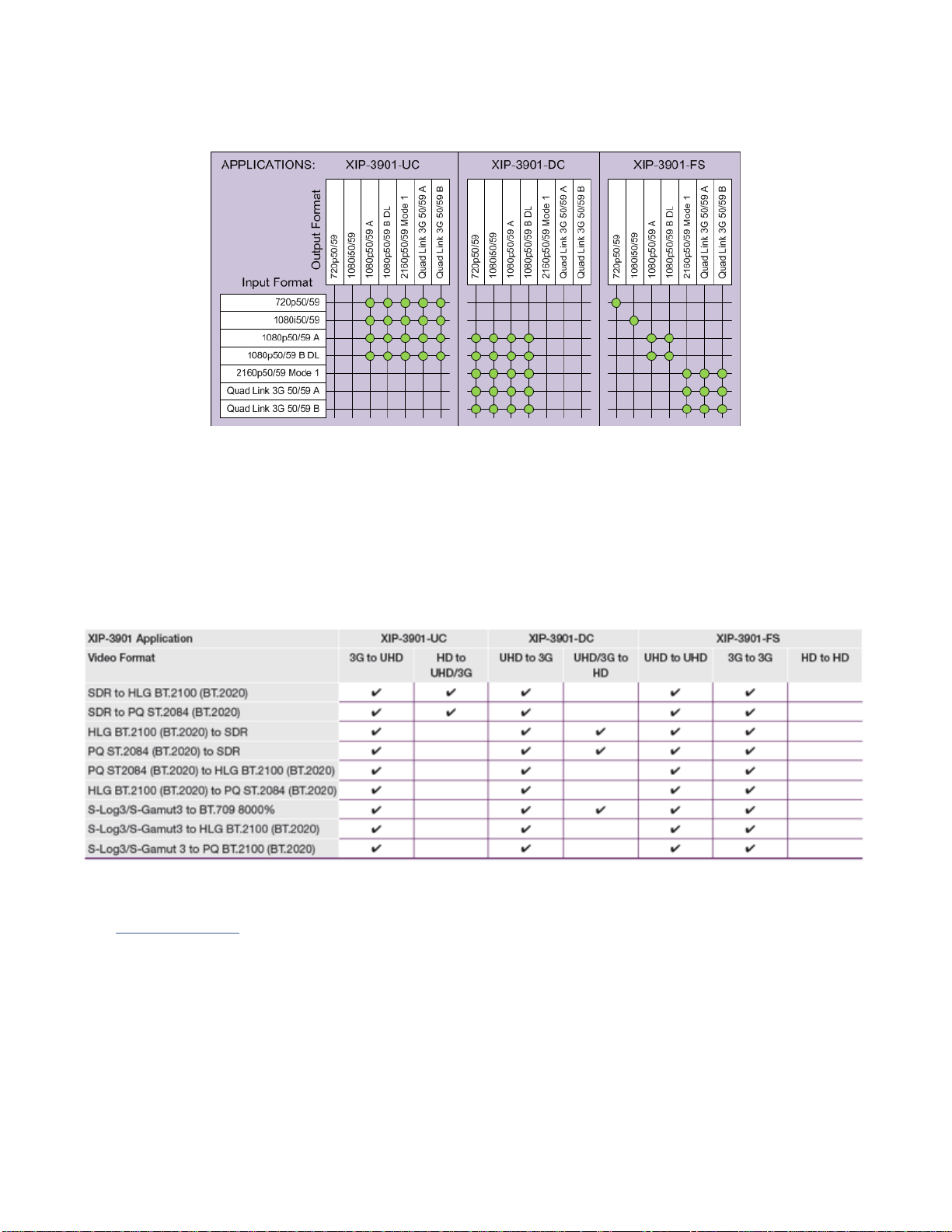
Supported Video Formats................................................................................................................... 32.2
Optional HDR Processing................................................................................................................... 32.3
Functional Block Diagrams ................................................................................................................. 42.4
3Front Card-edge Interface .......................................................................................................5
4Installation................................................................................................................................6
Installing the Rear Connector Panel................................................................................................... 64.1
Installing the XIP-3901 Card............................................................................................................... 64.2
Rear Connector Panel ........................................................................................................................ 74.3 4.3.1 Image of the Rear Connector Panel ...................................................................................... 7
4.3.2 Summary of Rear Panel Connections ................................................................................... 7
4.3.3 Details of Rear Panel Connections........................................................................................ 8
5User Interface.........................................................................................................................10
Control Methods................................................................................................................................ 105.1
Card-edge Status LED...................................................................................................................... 105.2
6Local Control Using the Densité Frame Control Panel .......................................................12
7iControl System User Interface.............................................................................................13
8Configuring the XIP-3901 Using iControl .............................................................................18
Video Input/Output Panel (XIP-3901-UC)......................................................................................... 188.1 8.1.1 Input/Output Config Tab....................................................................................................... 18
8.1.2 Timing Tab........................................................................................................................... 20
8.1.3 Deglitcher Tab...................................................................................................................... 22
8.1.4 De-interlacer Tab ................................................................................................................. 23
Video Input/Output Panel (XIP-3901-DC)......................................................................................... 248.2 8.2.1 Input/Output Config Tab....................................................................................................... 24
8.2.2 Timing Tab........................................................................................................................... 26
8.2.3 Deglitcher Tab...................................................................................................................... 28
Video Input/Output Panel (XIP-3901-FS) ......................................................................................... 298.3 8.3.1 Input/Output Config Tab....................................................................................................... 29
8.3.2 Timing Tab........................................................................................................................... 32
8.3.3 Deglitcher Tab...................................................................................................................... 36
Clean Switch Regions and Examples............................................................................................... 378.4
Video Processing Panel.................................................................................................................... 408.5
Reference Panel ............................................................................................................................... 438.6
Test Panel......................................................................................................................................... 458.7
Network Panel................................................................................................................................... 468.8
Options Panel.................................................................................................................................... 478.9
Factory/Presets Panel....................................................................................................................... 488.10 8.10.1 User Presets ........................................................................................................................ 49
8.10.2 Factory................................................................................................................................. 50
8.10.3 Profiles................................................................................................................................. 51

INSTALLATION AND OPERATION GUIDE
XIP-3901
Alarm Config Panel........................................................................................................................... 538.11
Info Panel.......................................................................................................................................... 558.12
Application Panel .............................................................................................................................. 588.13
9Fan Replacement ...................................................................................................................59
Required Materials............................................................................................................................ 609.1
Procedure.......................................................................................................................................... 609.2
10 Specifications.........................................................................................................................61
11 Contact Us..............................................................................................................................63
Grass Valley Technical Support................................................................................................................. 63
Corporate Head Office............................................................................................................................... 63
APPENDIX 1 –Local Menu..........................................................................................................64

INSTALLATION AND OPERATION GUIDE
XIP-3901 | 1
1 Introduction to the XIP-3901 Agile SDI/IP Processing Platform
The Densité 3+ XIP-3901 from Grass Valley, a Belden Brand, is a new agile processing platform that focuses on
high-quality live production for HD, 1080p, 4K UHD and HDR. This platform is a bridge for the hybrid world,
consisting of today’s proven SDI technology and the IP connectivity of tomorrow.
Figure 1
Densité 3+ XIP-3901
To meet customers’ needs both now and in the future, the XIP-3901 uses a flexible “virtualized” hardware
platform. Based on a powerful FPGA engine, the XIP-3901 can be reconfigured with software updates for different
applications as requirements change.
Figure 2
XIP-3901 Agile IP/SDI Processing Platform
The XIP-3901 agile processing platform with a rear XIP-3901-3+DRP comes with all the 12G/Quad Link
3G/3G/HD-SDI connectivity to support two 4K UHD processing paths with dual 25 GbE SFP cages for future IP
I/O migration. The XIP-3901 is installed in the established Densité modular frame. Due to advanced processing
capabilities and power requirements, the XIP-3901 is supported by the Densité 3+ FR1 and FR4 frames.
Based on the proven Densité modular framework of over 100 cards, the flexible, space-efficient XIP-3901 agile
processing platform can accommodate a gradual adoption of different production elements into 1080p and 4K
UHD broadcasting workflows —and enables dual HDR/SDR production —all while protecting your investment in
installed equipment. With flexibility to configure up to 12 XIP-3901 dual-channel processing applications per
Densité 3+ FR4 frame, the Densité platform scales to a market-leading density of 24 4K UHD processors with
HDR conversions in a 4 RU frame. This means space and cost-efficient scaling today and tomorrow. The XIP-
3901 is integrated with iControl customized end-to-end facility monitoring to provide configuration, alarms and
logging services.

INSTALLATION AND OPERATION GUIDE
2| XIP-3901
2 XIP-3901 Applications
The initial applications for the XIP-3901 agile IP/SDI processing platform provides full functionality of
up/down/framesync-gearbox processing capability delivered through three applications that allow your live
productions —either from trucks, venues or stadiums —to make the most of the new 4K UHD and HDR formats.
This includes playout channels where output of a 4K UHD HDR channel needs to be downconverted for an HD
SDR simulcast version.
Densité 3+ XIP-3901-UC is an application that provides a dual-channel 12G/Quad Link 3G/3G/HD-SDI
upconverter, which is designed to synchronize, upconvert and process HD and 3G 1080p signals for both 1080p
and 4K UHD 2160p broadcast production. The XIP-3901-UC application features broadcast-quality scalers,
motion-adaptive de-interlacers and color space conversions from ITU-R BT.709 to ITU-R BT.2020.
Densité 3+ XIP-3901-DC is an application that provides a dual-channel 12G/Quad Link 3G/3G/HD downconverter,
which is designed to synchronize, downconvert and process 4K UHD 2160p and 1080p for both 1080p and HD
broadcast production. The XIP-3901-DC application features broadcast-quality down-scalers, interlacers and
color space conversions from ITU-R BT.2020 to ITU-R BT.709.
Densité 3+ XIP-3901-FS is an application that provides a dual-channel 12G/Quad Link 3G/3G/HD frame
synchronizer with gearbox functionality, which is designed to synchronize and convert color space between ITU-R
BT.2020 and ITU-R BT.709 in 4K UHD, 1080p and HD broadcast productions.
All applications will delay 12G/3G/HD embedded audio and metadata to maintain synchronization with video. The
optional HDR processor, XIP-3901-UDC-HDR, allows conversion between SDR and HDR formats, supporting
HLG (ITU-R BT.2100), PQ (TU-R BT.2100) and S-Log3/S-Gamut3 formats, with conversion between formats.
Key Features2.1
Independent dual processing channels
12G 2160p, 3G 1080p and HD 1080i/720p input/output (depending on application)
12G-SDI Mode 1 and Type 1
Quad Link 3G in 2SI and Square Division
3G Level A & Level B Dual Link
High-quality scaler and advanced de-interlacer on XIP-3901-UC
High-quality downscaler and interlacer on XIP-3901-DC
12G-SDI to/from Quad Link 3G in 2SI/Square Division on XIP-3901-FS
Integrated frame synchronizer (freeze to last valid frame/field on error)
Minimum processing delay mode available on XIP-3901-FS
Audio/video deglitcher to handle video hot switch at the input
Broadcast-quality color conversion (between ITU-R BT.709 and ITU-R BT.2020)
SDR/HDR optional processing support
External reference or URS frame reference
Embedded audio and metadata delay and synchronization
Individual application licensed, purchased as needed
Rapid switching between applications

INSTALLATION AND OPERATION GUIDE
XIP-3901 | 3
Supported Video Formats2.2
Figure 3
Supported Video Formats for XIP-3901 Applications
Note: Standard rate conversion 50/59.94 Hz is not supported.
Optional HDR Processing2.3
The XIP-3901 applications include ITU-R BT.709 and ITU-R BT.2020 color space conversions. The XIP-3901-
UDC-HDR option adds HDR/SDR up-mapping and down-mapping capabilities, as summarized in the following
table:
Figure 4
HDR/SDR Up-mapping and Down-mapping Capabilities
See 8.9 Options Panel for how to enable the options.

INSTALLATION AND OPERATION GUIDE
4| XIP-3901
Functional Block Diagrams2.4
Figure 5
XIP-3901-UC Functional Block Diagram
Figure 6 XIP-3901-DC Functional Block Diagram
A/V
Deglitcher Frame
Sync 709/2020
Convert
Optional
HDR
Processor
De-
interlacer/
Scaler
3G/HD SDI IN 1 Quad
Link 3G
2SI/SD
Convert
16ch Audio Tracking / Metadata Match Delay
12G/3G SDI OUT 1
A/V
Deglitcher Frame
Sync 709/2020
Convert
Optional
HDR
Processor
16ch Audio Tracking / Metadata Match Delay
REF IN
Upgrade & Control
DENSITÉ 3+ FR4 STD or
DENSITÉ 3+ FR4 ADV
1 Gb Eth
1 Gb Eth
ETH3
DENSITÉ CONTROL
3G SDI OUT 2
3G SDI OUT 3
3G SDI OUT 4
XIP-3901-UC 12G/Quad Link 3G/3G/HD Dual Upconverter with Optional HDR Processing Application
URS
Genlock
3G/HD SDI IN 5
Tone/
Color-
Bar
Link 1
Link 2
Link 3
Link 4
Quad
Link 3G
2SI/SD
Convert
12G/3G SDI OUT 5
3G SDI OUT 6
3G SDI OUT 7
3G SDI OUT 8
Tone/
Color-
Bar
Link 1
Link 2
Link 3
Link 4
De-
interlacer/
Scaler
XIP-3901-UDC-HDR
OPTIONAL LICENSE:
16ch Audio Tracking / Metadata Match Delay
REF IN URS
Upgrade & Control
1 Gb Eth
1 Gb Eth
ETH3
DENSITÉ CONTROL
Quad
Link 3G
2SI/SD
Convert
A/V
Deglitcher
Frame
Sync 709/2020
Convert
Optional
HDR
Processor
12G/3G SDI IN 1
3G SDI IN 2
3G SDI IN 3
3G SDI IN 4
16ch Audio Tracking / Metadata Match Delay
Quad
Link 3G
2SI/SD
Convert
A/V
Deglitcher
Frame
Sync 709/2020
Convert
Optional
HDR
Processor 3G/HD SDI OUT 5
12G/3G SDI IN 5
3G SDI IN 6
3G SDI IN 7
3G SDI IN 8
Genlock
Link 1
Link 2
Link 3
Link 4
Link 1
Link 2
Link 3
Link 4
Interlacer
/Scaler
Tone/
Color-
Bar
3G/HD SDI OUT 1
Interlacer
/Scaler
Tone/
Color-
Bar
DENSITÉ 3+ FR4 STD or
DENSITÉ 3+ FR4 ADV
XIP-3901-DC 12G/Quad Link 3G/3G/HD Dual Downconverter with Optional HDR Processing Application
XIP-3901-UDC-HDR
OPTIONAL LICENSE:

INSTALLATION AND OPERATION GUIDE
XIP-3901 | 5
Figure 7 XIP-3901-FS Functional Block Diagram
3 Front Card-edge Interface
The front card-edge of the XIP-3901 incorporates two elements:
Status LED (see 5.2 Card-edge Status LED)
Select button (see 6 Local Control Using the Densité Frame Control Panel)
Figure 8
Front Card-edge Layout
REF IN URS
Upgrade & Control
1 Gb Eth
1 Gb Eth
ETH3
DENSITÉ CONTROL
A/V
Deglitcher
3G SDI IN 2
3G SDI IN 3
3G SDI IN 4
A/V
Deglitcher
3G SDI IN 6
3G SDI IN 7
3G SDI IN 8
Genlock
Link 1
Link 2
Link 3
Link 4
Link 1
Link 2
Link 3
Link 4
12G/
Quad
Link 3G
2SI/SD
Convert/
Gearbox
12G/3G/HD SDI OUT 1
3G SDI OUT 2
3G SDI OUT 3
3G SDI OUT 4
Link 1
Link 2
Link 3
Link 4
12G/
Quad
Link 3G
2SI/SD
Convert/
Gearbox
12G/3G/HD SDI OUT 5
3G SDI OUT 6
3G SDI OUT 7
3G SDI OUT 8
Link 1
Link 2
Link 3
Link 4
XIP-3901-FS 12G/Quad Link 3G/3G/HD Dual Frame Sync/Gearbox with Optional HDR Processing Application
12G/3G/HD SDI IN 1
12G/3G/HD SDI IN 5
DENSITÉ 3+ FR4 STD or
DENSITÉ 3+ FR4 ADV
XIP-3901-UDC-HDR
OPTIONAL LICENSE:
16ch Audio Tracking / Metadata Match Delay
Frame
Sync 709/2020
Convert
Optional
HDR
Processor
Tone/
Color-
Bar
Fixed
Delay
12G/
Quad
Link 3G
2SI/SD
Convert/
Gearbox
Frame
Sync 709/2020
Convert
Optional
HDR
Processor
Tone/
Color-
Bar
Fixed
Delay
Only used
with Quad
Link 3G
Only used
with Quad
Link 3G
Select Button
IRD-3802
Status LED
Status
Select
XIP-3901

INSTALLATION AND OPERATION GUIDE
6| XIP-3901
4 Installation
Installing the Rear Connector Panel4.1
Each Grass Valley Densité-series card is associated with a rear connector panel, which must be installed in the
Densité frame before the card can be inserted.
The XIP-3901 card is designed to fit into Grass Valley’s Densité 3+ frames. One rear connector panel is available:
XIP-3901-3+DRP: Double rear connector panel for Densité 3+
See 4.3 Rear Connector Panel for details about the signal connections available on this panel.
All cards and rear connector panels can be installed with the frame powered on. The card has connectors that
plug into a mid-frame motherboard to distribute power and connect to the controller card, as well as a second
connector that plugs directly into the rear connector panel for input and output.
To install the connector panel:
The rear connector panel must be installed with the card out of the frame.
1. If a card is installed in the slot for which the rear connector panel is being changed, it must be removed.
Tilting the swivel handle on the front of the card to lever the connectors apart, and then use the handle to
pull the card straight out of the slot.
2. Remove the existing rear connector panel (either blank or belonging to an existing card that is being
changed) by releasing the captive screw(s) at the bottom (Densité 3+ or Densité-3+FR4) or on the side
(Densité-3+FR1) of the panel.
3. Position the new rear connector panel and secure it in place with the captive screw(s) at the bottom or on
the side.
Installing the XIP-3901 Card4.2
Once a matching rear connector panel is in place, install the XIP-3901 card as follows:
1. Open the front panel of the frame.
2. Slide the XIP-3901 card into the slot and push gently on the handle to seat the connectors.
When using a double-slot-width rear panel in a Densité-3+FR1 frame, the card should be inserted into
the lower of the two slots.
When using a double-slot-width rear panel in a Densité-3+FR4 frame, the card should be inserted into
the rightmost of the two slots.
Inserting the card into the wrong slot will not damage the card, but the status LED on the card will flash red
to indicate that there is no connection to the rear panel.
3. Close the front panel of the frame.

INSTALLATION AND OPERATION GUIDE
XIP-3901 | 7
Rear Connector Panel4.3
Image of the Rear Connector Panel4.3.1
The rear connector panel is shown in Figure 9. Details of the inputs and outputs are described below.
Figure 9 XIP-3901 Rear Panel
Summary of Rear Panel Connections
4.3.2
Connectors
Count
REF IN
1
3G/HD IN
6
12G/3G/HD IN
2
3G/HD OUT
6
12G/3G/HD OUT
2
25 GigE on fiber (SFP+)
2 (Note)
1 GigE on RJ-45
1
Note: 25 GigE on fiber (SFP+) is not supported in this release.

INSTALLATION AND OPERATION GUIDE
8| XIP-3901
Details of Rear Panel Connections4.3.3
REF IN –External reference
Connect an NTSC or PAL reference signal (SMPTE 170M / SMPTE 318M / ITU 624-4 black burst).
12G/3G/HD IN –Serial digital 3G/HD inputs
Connect serial digital video signals, conforming to SMPTE ST 2081 and ST 2082 for 12G input signals, SMPTE
425M for 3G input signals or SMPTE 292M for HD input signals, to the connectors specified in the tables below.
Connector
XIP-3901-UC Input Signal
12G/3G/HD IN 1
UC1 3G/HD SDI
3G/HD IN 2
Not used
3G/HD IN 3
Not used
3G/HD IN 4
Not used
12G/3G/HD IN 5
UC2 3G/HD SDI
3G/HD IN 6
Not used
3G/HD IN 7
Not used
3G/HD IN 8
Not used
Connector
XIP-3901-DC Input Signal
12G/3G/HD IN 1
DC1 Quad Link 3G - Link 1/12G/3G
3G/HD IN 2
DC1 Quad Link 3G - Link 2
3G/HD IN 3
DC1 Quad Link 3G - Link 3
3G/HD IN 4
DC1 Quad Link 3G - Link 4
12G/3G/HD IN 5
DC2 Quad Link 3G - Link 1/12G/3G
3G/HD IN 6
DC2 Quad Link 3G - Link 2
3G/HD IN 7
DC2 Quad Link 3G - Link 3
3G/HD IN 8
DC2 Quad Link 3G - Link 4
Connector
XIP-3901-FS Input Signal
12G/3G/HD IN 1
FS1 Quad Link 3G - Link 1/12G/3G
3G/HD IN 2
FS1 Quad Link 3G - Link 2
3G/HD IN 3
FS1 Quad Link 3G - Link 3
3G/HD IN 4
FS1 Quad Link 3G - Link 4
12G/3G/HD IN 5
FS2 Quad Link 3G - Link 1/12G/3G
3G/HD IN 6
FS2 Quad Link 3G - Link 2
3G/HD IN 7
FS2 Quad Link 3G - Link 3
3G/HD IN 8
FS2 Quad Link 3G - Link 4

INSTALLATION AND OPERATION GUIDE
XIP-3901 | 9
12G/3G/HD OUT –Serial digital 12G/3G/HD outputs
SDI output signals appear on the rear panel connectors as shown in the table, conforming to SMPTE ST 2081
and ST 2082 for 12G output signals, SMPTE 425M for 3G output signals or SMPTE 292M for HD output signals.
Connector
XIP-3901-UC Output Signal
12G/3G/HD OUT 1
UC1 Quad Link 3G - Link 1/12G/3G
3G/HD OUT 2
UC1 Quad Link 3G - Link 2
3G/HD OUT 3
UC1 Quad Link 3G - Link 3
3G/HD OUT 4
UC1 Quad Link 3G - Link 4
12G/3G/HD OUT 5
UC2 Quad Link 3G - Link 1/12G/3G
3G/HD OUT 6
UC2 Quad Link 3G - Link 2
3G/HD OUT 7
UC2 Quad Link 3G - Link 3
3G/HD OUT 8
UC2 Quad Link 3G - Link 4
Connector
XIP-3901-DC Output Signal
12G/3G/HD OUT 1
DC1 3G/HD SDI
3G/HD OUT 2
Not used
3G/HD OUT 3
Not used
3G/HD OUT 4
Not used
12G/3G/HD OUT 5
DC2 3G/HD SDI
3G/HD OUT 6
Not used
3G/HD OUT 7
Not used
3G/HD OUT 8
Not used
Connector
XIP-3901-FS Output Signal
12G/3G/HD OUT 1
FS1 Quad Link 3G - Link 1/12G/3G
3G/HD OUT 2
FS1 Quad Link 3G - Link 2
3G/HD OUT 3
FS1 Quad Link 3G - Link 3
3G/HD OUT 4
FS1 Quad Link 3G - Link 4
12G/3G/HD OUT 5
FS2 Quad Link 3G - Link 1/12G/3G
3G/HD OUT 6
FS2 Quad Link 3G - Link 2
3G/HD OUT 7
FS2 Quad Link 3G - Link 3
3G/HD OUT 8
FS2 Quad Link 3G - Link 4
ETH1, ETH2 –25 GigE on fiber (SFP+)
Transmit and receive video/audio/metadata streams.
Note: Not used in this release.
ETH3 –1 GigE on RJ-45
The network port can be used for Densité Upgrade Manager (DUM) upgrades.

INSTALLATION AND OPERATION GUIDE
10 | XIP-3901
5 User Interface
Control Methods5.1
The XIP-3901-UC, XIP-3901-DC, and XIP-3901-FS applications can be controlled in two different ways:
The local control panel and its buttons can be used to move through a menu of status reports (see 6 Local
Control Using the Densité Frame Control Panel).
Grass Valley’s iControl system can be used to access the card’s operating parameters remotely using a
convenient graphical user interface (GUI) (see 7 iControl System User Interface).
Card-edge Status LED5.2
The status LED is located on the front card-edge of the XIP-3901 and is visible through the front access door of
the Densité-3 frame. This LED indicates the status of the XIP-3901 using different colors and by flashing/steady
illumination.
The table shows how the various error conditions that can be flagged on the XIP-3901 affect the LED status.
If a cell is gray, the LED cannot be configured to assume that status.
If more than one LED status is possible for a particular error condition, the status is configurable. See
8.11 Alarm Config Panel for details.
The factory default status, if available, is marked with a .
The LED will always show the most severe error status that has been detected and that it is configured to display.
In the chart, error severity increases from left to right. Green represents no error/disabled, and flashing red
represents the most severe error.
Note: If the LED is flashing yellow, the card has been selected for local control using the Densité frame control
panel. See 6 Local Control Using the Densité Frame Control Panel) for details.
Error Condition
LED Status
Green
Yellow
Red
Flashing
Red
Hardware failure
Wrong or missing rear connector panel
UC1/DC1/FS1 IN1 –No carrier
UC1/DC1/FS1 IN1 –Unsupported
UC1/DC1/FS1 IN1 –Video/TRS error
UC1/DC1/FS1 IN1 –Reference mismatch
DC1/FS1 IN2 –No carrier
DC1/FS1 IN2 –Unsupported
DC1/FS1 IN2 –Video/TRS error
DC1/FS1 IN2 –Reference mismatch
DC1/FS1 IN3 –No carrier
DC1/FS1 IN3 –Unsupported
DC1/FS1 IN3 –Video/TRS error

INSTALLATION AND OPERATION GUIDE
XIP-3901 | 11
DC1/FS1 IN3 –Reference mismatch
DC1/FS1 IN4 –No carrier
DC1/FS1 IN4 –Unsupported
DC1/FS1 IN4 –Video/TRS error
DC1/FS1 IN4 –Reference mismatch
DC1/FS1 –Quad Link 3G ALIGN
UC2/DC2/FS2 IN5 –No carrier
UC2/DC2/FS2 IN5 –Unsupported
UC2/DC2/FS2 IN5 –Video/TRS error
UC2/DC2/FS2 IN5 –Reference mismatch
DC2/FS2 IN6 –No carrier
DC2/FS2 IN6 –Unsupported
DC2/FS2 IN6 –Video/TRS error
DC2/FS2 IN6 –Reference mismatch
DC2/FS2 IN7 –No carrier
DC2/FS2 IN7 –Unsupported
DC2/FS2 IN7 –Video/TRS error
DC2/FS2 IN7 –Reference mismatch
DC2/FS2 IN8 –No carrier
DC2/FS2 IN8 –Unsupported
DC2/FS2 IN8 –Video/TRS error
DC2/FS2 IN8 –Reference mismatch
DC2/FS2 –Quad Link 3G ALIGN
UC1/DC1/FS1 –Reference present
UC1/DC1/FS1 –Reference supported
UC1/DC1/FS1 –Reference locked
UC2/DC2/FS2 –Reference present
UC2/DC2/FS2 –Reference supported
UC2/DC2/FS2 –Reference locked
UC1/DC1/FS1 –Color Bars & Tone enabled
UC2/DC2/FS2 –Color Bars & Tone enabled
ETH3 –Network link up

INSTALLATION AND OPERATION GUIDE
12 | XIP-3901
6 Local Control Using the Densité Frame Control Panel
There are two types of local control panels:
Panel type
Frame models
Appearance
Physical
Densité-3+FR1
Touch-screen
Densité-3+FR4, GV Node
To assign the local control panel to the XIP-3901:
Physical panel: Open the front door of the frame to access the panel. Push the [SELECT] button on the
front of the card (see 3 Front Card-edge Interface).
Touch-screen panel: Use the opening in the frame door to access the panel. On the home screen, touch the
icon that corresponds to the card.
The status LED on the XIP-3901 will flash yellow, and the touch-screen status will be yellow for the XIP-3901.
The panel displays two lines of 16 characters and the following four buttons for navigating the menu:
[+] [–] Navigate menus and modify values.
[SEL] Accesses the next menu level. When a parameter value is shown, push this button once to modify the
value using the [+] and [–] buttons; push it again to confirm the new value.
[ESC] Cancels parameter value changes that have not been confirmed and reverts the parameter to its
former value.
Returns to the previous menu. In the main menu, [ESC] does not exit the menu system. To exit, push
the [SELECT] button on the card being controlled.
If no controls are operated for 30 seconds, the controller reverts to its normal standby status, and the selected
card’s status reverts to its normal operating mode.
The complete menu structure is shown in APPENDIX 1 –Local Menu.

INSTALLATION AND OPERATION GUIDE
XIP-3901 | 13
7 iControl System User Interface
The XIP-3901 applications can be remotely controlled using Grass Valley’s iControl system. This manual
describes the control panels associated with the XIP-3901 applications and their use. Please consult the iControl
User’s Guide for information about setting up and operating iControl.
In iControl Navigator or iControl Websites, double-click on the XIP-3901-UC, XIP-3901-DC, or XIP-3901-FS icon
(the icon says XIP-3901 for XIP-3901-UC v1.0) to open the control panel.
The basic window structure is shown in Figure 10. Although the example displayed is from the XIP-3901-UC, the
XIP-3901-DC and XIP-3901-FS interfaces follow the same structure. The window title bar shows the card type
and the slot number where the card is installed in its Densité frame.
There are four main sections in the window:
Figure 10
XIP-3901 iControl Graphic Interface (Shown on XIP-3901-UC)

INSTALLATION AND OPERATION GUIDE
14 | XIP-3901
Section 1: The top section displays eight icons (for XIP-3901-UC) or seven icons (for XIP-3901-DC and XIP-
3901-FS) that report different statuses, such as the card communication status, input status, health status, and
card operation mode. Mousing over an icon will display a status message with additional information.
Figure 11
XIP-3901-UC Status Icons
Figure 12
XIP-3901-DC Status Icons
Figure 13
XIP-3901-FS Status Icons
Figure 14
XIP-3901 Status Message (Shown on XIP-3901-UC)
The table below describes the various iControl status icons that can appear. If more than one interpretation is
possible, read the error message in the iControl window to see which applies.
Manual Card Configuration
(green)
Remote card control is activated. The iControl interface can be used to operate the card.
(yellow)
Local card control is activated. The card is being controlled using the Densité frame control
panel, as described in 6 Local Control Using the Densité Frame Control Panel. Any
changes made using the iControl interface will have no effect on the card.
SDI IN Status (UC only)
(green)
SDI is present and valid. The video format is indicated when there are no errors.
(red)
SDI not present; or
SDI invalid; or
SDI unsupported; or
Reference mismatch.
Other manuals for GRASS VALLEY XIP-3901
1
Table of contents
Other Belden Media Converter manuals

Belden
Belden thinklogical Velocitykvm-4 User manual

Belden
Belden Grass Valley LUMO User manual

Belden
Belden grass valley IRD-3811 Instruction Manual

Belden
Belden Hirschmann OZDV 2471 P Manual

Belden
Belden Grass Valley SME-1901 Instruction Manual

Belden
Belden Grass Valley Kayenne K-Frame Supplement

Belden
Belden Grass Valley EC9535 User manual

Belden
Belden Grass Valley K-Frame Supplement

Belden
Belden Grass Valley Kayenne K-Frame User manual

Belden
Belden Grass Valley K-Frame User manual