Belimo LonWorks GMX24-LON User manual
800-543-9038 USA 866-805-7089 CANADA 203-791-8396 LATIN AMERICA
2
07
G
MX24-L
ON
Lo
n
Wo
r
ks
®
,
Non-Sprin
g
Return, 24 V
Technical Data GMX24-LON
P
ower su
pp
l
y
24 VA
C
± 20% 50
/
60 H
z
24 VDC ± 10%
P
ower consumptio
n
4.5 W
(
1.5 W
)
T
rans
f
ormer sizin
g
7 VA
(
Class 2 power source
)
E
lectrical connectio
n
18 GA
p
lenum rated cabl
e
1
/
2” conduit connecto
r
protected NEMA 2 (IP54
)
3
f
t [1m
]
O
verload protectio
n
electronic throu
g
hout 0 to 95° rotation
An
g
le o
f
rotatio
n
max. 95°, ad
j
ustable with mechanical stop
e
l
ectron
i
ca
ll
y var
i
a
ble
T
orqu
e
360 in-lb [40 Nm]
Direction o
f
rotatio
n
r
e
v
e
r
s
i
b
l
e
with
s
wit
ch
P
osition indicatio
n
reflective visual indicator
(
snap-on
)
M
anua
l
overr
ide
externa
l
pus
h
b
utto
n
R
unn
i
ng t
i
m
e
150 seconds (default)
H
umidit
y
5 to 95% RH non condensin
g
(
EN 60730-1
)
Ambient tem
p
eratur
e
-22°F to +122°F
[
-30°C to +50°C
]
Storage temperature -40°F to +176°F [-40°C to +80°C]
H
ousin
g
NEMA 2, IP54, UL enclosure t
yp
e 2
H
ousin
g
materia
l
UL94-5VA
A
g
ency listin
g
s
†
cULus acc. to UL 60730-1A/-2-14
,
C
AN
/CS
A E60730-1:02
,
C
E
acc
. t
o
2
00
4
/
1
08/
EE
C
a
n
d
2
006/95/
E
C
No
i
se
l
e
v
el
<45dB
(
A
)
S
ervicin
g
m
a
int
e
n
a
n
ce
f
r
ee
Q
uality standar
d
I
SO
9001
W
ei
g
ht 3.4 lbs
[
1.55 k
g]
†
Rated Impulse Volta
g
e 800V, Type of action 1, Control Pollution De
g
ree 3
.
L
on
W
or
k
s
®
Ce
rtifi
ed
accordin
g
to Lo
n
M
ARK
®
3
.
3
P
r
ocessor
N
eu
r
o
n
3
12
0
T
r
a
n
sce
iv
er
FTT-10A, compatible with LPT-10
F
unctional pro
f
il
e
accor
di
n
g
to
L
o
n
MARK
®
D
ampe
r
actuator object #8110
open loop sensor object #1
L
NS plug-in for actuator/sensor can be run with any LNS based integratio
n
tool (min. for LN
S
3.x
)
S
ervice button and status LED accor
di
ng to
L
o
n
MARK
®
gu
id
e
li
ne
s
C
onductors, cables conductor lengths, cable specifications and
topology of the LonWorks
®
network according to
the Echelon
®
directive
s
Lo
nW
o
rk
s
a
n
d
L
o
nMAR
K
©
2
00
7-2
009
L
o
nM
a
rk Int
e
rn
a
ti
o
n
al
Tiilbf lfd f f
T
orque m
i
n. 360
i
n-
lb
f
or contro
l
o
f
d
amper sur
f
aces up to 90 sq
f
t
.
A
pp
l
i
cat
i
o
n
Direct coupled actuators
f
or direct link to LonWorks network. Actuators are easily
installed by direct shaft mounting on air dampers in ventilation and air conditioning
systems. Actuator can be controlled by any compatible L
O
N system
.
F
or proportional modulation of dampers in HVAC systems. Actuator sizing should be
done in accordance with the damper manufacturer’s specifications.
The actuator is mounted directly to a damper shaft up to 1.05” in diameter by means
of its universal clamp. A crank arm and several mountin
g
brackets are available for
a
pp
lications where the actuator cannot be direct cou
p
led to the dam
p
er shaft
.
O
p
eratio
n
The actuator is not
p
rovided with and does not re
q
uire an
y
limit switches, but is
electronically protected a
g
ainst overload. The anti-rotation strap supplied with the
actuator will prevent lateral movement
.
The GMX24-LON series
p
rovides 95° of rotation and a visual indicator indicates
position of the actuator. When reachin
g
the damper or actuator end position, the
actuator automat
i
ca
ll
y stops.
Th
e gears can
b
e manua
ll
y
di
sengage
d
w
i
t
h
a
b
utton on
t
h
e actuator cover.
The
G
MX24-L
O
N actuators use a brushless D
C
motor, which is controlled by an
A
A
pplication Specific Inte
g
rated Circuit
(
ASIC
)
. The ASIC monitors and controls the
actuator’s rotation and provides a di
g
ital rotation sensin
g
(
DRS
)
function to prevent
d
ama
g
e to t
h
e actuator
i
n a sta
ll
con
di
t
i
on.
P
ower consumpt
i
on
i
s re
d
uce
d
i
n
h
o
ldi
n
g
mo
d
e
.
A
A
dd-on auxiliary switches or feedback potentiometers are easily fastened directly onto
the actuator body
f
or si
g
nalin
g
and switchin
g
f
unctions
.
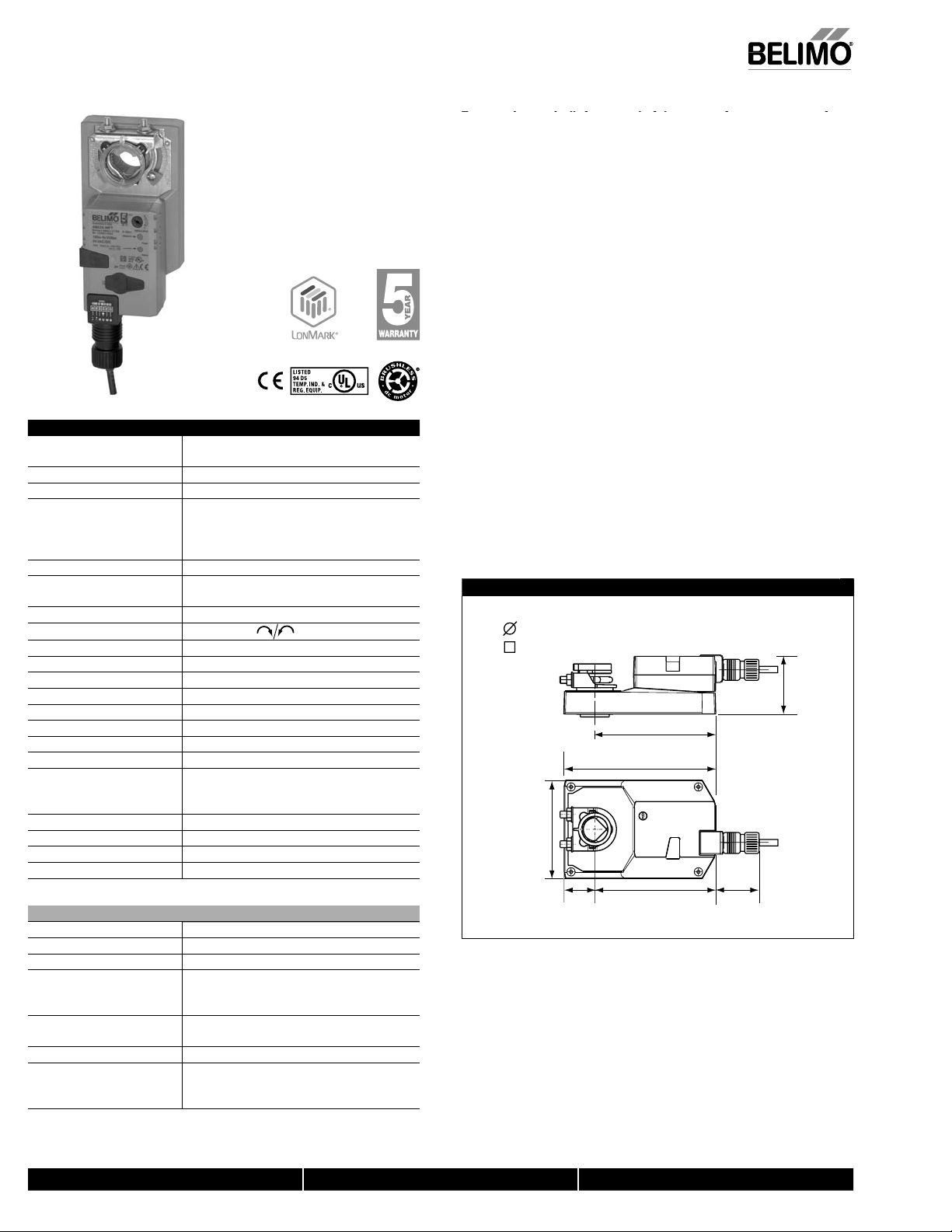
Dimensions (Inches [mm])
2.9” [72.9]
4.55” [115.6]
7.02” [178.4]
5.37” [136.4]
1.42”
[36]
5.6” [142.4] 2” [50.8]
1/2” to 1.05” [12.7 to 26.67]
2/5” to 1.05” [10 to 26.67]
To center of
mounting slot.
D12
3
M40024 - 05/10 - Subject to change. © Belimo Aircontrols (USA), Inc.
800-543-9038 USA 866-805-7089 CANADA 203-791-8396 LATIN AMERICA
208
Accessories
K-
G
M20 3
/
4" [20 mm]
S
haft
C
lam
p
ZG-102 Multiple Actuator Mounting Bracke
t
ZG-GMA Crank arm Adaptor Kit
ZG-JSA (-1, 2, 3
)
Jackshaft Adaptors for Hollow Jackshaft
s
Z
S
-100 Weather
S
hield -
S
tee
l
Z
S
-1
50
Weather Shield - Pol
y
carbonate
Z
S
-2
60
Explosion Proof Housin
g
Z
S
-300
(
-1
)
(
-5
)
NEMA
4
X
H
ous
i
n
g
T
ool-07 13 mm Wrench
P
S
-100 Actuator Power
S
upply
S
imulator
S
1A, S2A Auxiliary Switch (es
)
P
370
S
haft Mount Auxiliary
S
witc
h
P…A
Feedback Potentiometer
s
SG
A24 Min positioners in NEMA 4 housin
g
S
GF2
4
Min positioners for flush panel mountin
g
A
D
S
-100 Analo
g
to Di
g
ital
S
witch
NSV24 US Battery Back-Up Module
ZG-X40 Trans
f
orme
r
NO
TE
:
When usin
g
GMX24-LON actuators, only use accessories listed on this pa
g
e
.
Typical Specification
P
roport
i
ona
l
contro
l
d
amper actuators s
h
a
ll
b
e e
l
ectron
i
c
di
rect-coup
l
e
d
type, w
hi
c
h
r
equire no crank arm and linka
g
e and be capable of direct mountin
g
to a shaft up to
1.05” diameter. Actuators shall have brushless DC motor technology and be protected
f
rom overload at all an
g
les o
f
rotation. Actuators shall have reversin
g
switch and
manual override on the cover. Run time shall be constant and independent o
f
torque.
A
A
ctuators shall be cULus listed, have a 5-year warranty, and be manufactured under
ISO 9001 International Quality Control Standards. Actuators shall be as manufactured
by
Belimo.
Wiring Diagrams
V
P
oss
i
b
l
e
co
nn
ec
ti
o
n
o
f
a
v
oltmeter
f
or checkin
g
the
p
osition
f
eedback U.
567321
MFT
LON
LON
T
~
+
–
T
~
+
–
V
S
chema
_
L
O
N
_
01
Connection without Sensor
G
MX24-L
ON
Lo
nW
o
rk
s
®
, Non-
S
prin
g
Return, 24 V
567321
MFT
LON
LON
T
~
+
–
T
~
+
–
S
ensor scalin
g
:
T
he sensors can be scaled with the sensor plu
g
-in
(
sensor table
).
Sensor Temperature range Resistance range Resolution
Ni
100
0
–
28 ... +98°
C
8
50 ... 1600
Ω
1
Ω
PT
100
0
–35 ... +155°
C
8
50 ... 1600
Ω
1
Ω
NT
C
–1
0
... +1
60
°
C
(
dependin
g
on type
)
2
00
...
60
k
Ω
1
Ω
S
chema_L
O
N_02
Connection with Passive Sensor, e.g. Pt1000, Ni1000, NT
C
567321
MFT
LON
LON
T
~
+
–
T
~
+
–
Re
q
uirements fo
r
sw
i
tch
i
n
g
contact
:
The switching contact must be
able to accuratel
y
switch a cur-
r
e
nt
o
f 1
6
mA
@
24 V
.
S
chema_L
O
N_03
C
onnection with
S
witchin
g
C
ontact, e.
g
.
Δ
p
-mon
i
tor
567321
MFT
LON
LON
T
~
+
–
T
~
+
–
Poss
i
ble
i
nput volta
g
e ran
g
e:
0 ... 32 V
(
resolution 30 mV
)
S
ensor scalin
g
:
Th
e
se
n
so
r
s
ca
n
be
sca
l
ed
with th
e
s
ensor plug-in (sensor table)
S
chema_L
O
N_0
4
Connection with Active Sensor, e.
g
. 0...10 V @ 0...5
0
°
C
M40024 - 05/10 - Sub
j
ect to chan
g
e. © Belimo Aircontrols
(
USA
)
, Inc.

800-543-9038 USA 866-805-7089 CANADA 203-791-8396 LATIN AMERICA
2
09
G
MX24-L
ON
Lo
n
Wo
r
ks
®
,
Non-Sprin
g
Return, 24 V
Node ob
j
ect #0
T
he node ob
j
ect contains the ob
j
ect status and ob
j
ect request functions
.
n
viRequest SNVT_obj_reques
t
I
nput variable for requesting the status of a particular object in the node
.
n
vo
S
tatus
S
NVT_obj_statu
s
O
utput variable that outputs the current status of a particular object in the node
.
n
voFileDirectory
S
NVT_address
O
utput variable that shows information in the address range of the Neuron chip
.
D
amper actuator object #811
0
T
he actuator object is used to map the functions of the MP actuators to the
L
ONWORKS® network.
n
viRel
S
tpt
S
NVT_lev_percen
t
T
he nominal position is assi
g
ned to the actuator via this input variable. This variable is
n
ormally linked to the output variable of an HVAC controller
.
n
viActuateState SNVT
_
switc
h
A
preset position is assi
g
ned to the actuator via this input variable. Note on priority:
T
he last variable that was active, either nviActuatorState or nviRelSt
p
t, has
p
riorit
y
.
n
viManOvrd SNVT_hvac_overi
d
Th
ese
i
nput var
i
a
bl
es can
b
e use
d
to manua
ll
y overr
id
e t
h
e actuator
i
nto a part
i
cu
l
ar
p
osition
.
n
voActualValue
S
NVT_lev_
p
ercen
t
T
his out
p
ut variable shows the current actual
p
osition o
f
the actuator and can be used
for control circuit feedback or for displayin
g
positions
.
n
voAbsAngle
S
NVT_angle_deg
T
his output variable shows the current angle o
f
rotation o
f
the actuator
o
r the valve and can be used to dis
p
la
y
the
p
osition or for service
p
ur
p
oses.
n
voAbsAirFlow SNVT
_
flow
T
his out
p
ut variable is inactive with the SR24ALON-5 rotar
y
actuator and shows a
c
onstant value of 65535 (this variable is only active in conjunction with L
O
N-capable
V
AV controllers)
.
Op
en loo
p
sensor ob
j
ect #1
A
sensor can be connected to the rotary actuator. A passive resistance sensor
(
e.
g
.
N
i1000
)
, an active sensor
(
output 0 ... 32 V
)
or a switch
(
on/off
)
can be connected. The
o
pen loop sensor object transfers the measured sensor values to the L
O
NW
O
RK
S®
n
etwork
.
n
voSensorValue SNVT_xx
x
T
his output variable shows the current sensor value. Dependin
g
on the connected
s
ensor, the output variable can be con
f
i
g
ured via the sensor plu
g
-in and speci
f
ically
ad
apte
d
to t
h
e system
.
The SNVT_... can be configured as:
S
NVT_temp_
p
S
NVT_lev_percent
S
NVT_lux
S
NVT_tem
p
S
NVT_abs_humid
S
NVT_
p
ress_
p
S
NVT_switch
S
NVT_enthalp
y
S
NVT_smo_obscur
S
NVT
_
flow
S
NVT_ppm
S
NVT_power
S
NVT_flow_p
S
NVT_rpm
S
NVT_elec_kw
h
Notes
D
etailed information on the functional
p
rofiles can be found on the website of
LonMARK
®
K
K
(www.lonmark.org).
Functional Profile according to LonMARK
®
K
K
T
he L
O
N-ca
p
able dam
p
er actuator is certified b
y
LonMARK
®
. Th
e
ac
t
ua
t
o
r
fu
n
c
ti
o
n
s
are supp
li
e
d
w
i
t
h
t
h
e
L
on
W
or
ks
®
networ
k
as stan
d
ar
di
ze
d
networ
k
var
i
a
bl
es
according to LonMARK
®
. The Node Object #0, the Damper Actuator Object #8110
and the Open Loop SensorObject #1 are implemented in the actuator.
M40024 - 05/10 - Subject to change. © Belimo Aircontrols (USA), Inc.

800-543-9038 USA 866-805-7089 CANADA 203-791-8396 LATIN AMERICA
2
1
0
G
MX24-L
ON
Lo
nW
o
rk
s
®
, Non-
S
prin
g
Return, 24 V
1
Direction o
f
rotation switc
h
S
witchin
g
ove
r
Direction o
f
rotation chan
g
es
2
Pushbutton and green LED d
i
spla
y
O
f
f
No voltage supply or mal
f
unction
Green
,
on Operatio
n
Press butto
n
S
witches on angle of rotation adaption followed
b
y
standard o
p
eratio
n
3
Service button for commissioning LONWORK
S
®
and
y
ellow LED dis
p
la
y
for the LON statu
s
O
f
f
The SR24ALON-5 rotar
y
actuator is connected
and ready for operation in the
L
O
NW
O
RK
S®
network.
Y
e
ll
ow
,
o
n
No application software is loaded in the
SR24ALON-5
.
Yellow, flashin
g
(flashing interval 2 seconds)
The SR24ALON-5 is read
y
for o
p
eration but not
integrated in the L
O
NW
O
RK
S
®
networ
k
(
unconfi
g
ured
).
O
ther flashing codes A fault is present in the
S
R24AL
O
N-5
.
Press butto
n
Service Pin Messa
g
e is sent to the
LONWORK
S
®
n
etwork
.
4
Gear disen
g
a
g
ement switc
h
Pr
ess
bu
tt
on
Gear disen
g
a
g
ed, motor stops, manual operation
poss
ible
R
e
l
ease
b
utto
n
Gear engaged, synchronisation starts, followed
b
y stan
d
ar
d
operat
i
o
n
5
Service plu
g
For connectin
g
MFT parameterizin
g
and service tool
s
1
2
3
4
5
M40024 - 05/10 - Sub
j
ect to chan
g
e. © Belimo Aircontrols
(
USA
)
, Inc.
Other Belimo Control System manuals


Popular Control System manuals by other brands

RIB
RIB PRESIDENT manual

Opencockpits
Opencockpits B737 MAX AFT Overhead Installation & user manual

Dover
Dover NORRISEAL 1001 Series Operating and maintenance manual

Efka
Efka euramot AB60D1472 manual

Whelen Engineering Company
Whelen Engineering Company CanTrol Basic with Traffic Advisor Installation & operating guide

SALUPO
SALUPO IMPEDANCE 1 SQ701. Series Instruction and installation manual

AccuWeb
AccuWeb MICRO 4000 NET instruction manual

Siemens
Siemens SINUMERIK 840D sl Programming manual

Meccanica SCOTTI
Meccanica SCOTTI CNC Table Programming manual

Woodward
Woodward Vertex-Pro Installation/Hardware Manual

2VV
2VV AirGENIO Operation and use

Data Aire
Data Aire gPod Installation, operation & maintenance manual


