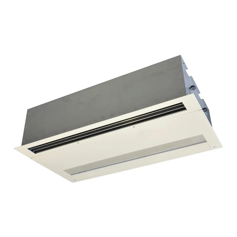
2VV AirGENIO User manual

EN
OPERATION AND HANDLING
AirGENIO
Comfort EC
2VV s.r.o.
Fáblovka 568, 533 52 Pardubice
Staré Hradiště, Czech Republic
www.2vv.cz, 2vv@2vv.cz
AirGENIO Control System
AirGENIO-MANUAL SD-CARD AirGENIO-PWR-SOURCE-12VDC
AirGENIO-PCB-MODULE-A AirGENIO-CONN.CABLE-UTP AirGENIO-PWR-SOURCE-24VCD
AirGENIO-TEMP.SENSOR-3,2M AirGENIO-CONTROL-PANEL
AirGENIO-PCB-MODULE-B
AirGENIO-TEMP.SENSOR-10M AirGENIO-PRESSURE-LP
AirGENIO-PCB-MODULE-G
AirGENIO-I-BUS-300MM AirGENIO-PRESSURE-HP
AirGENIO-PCB-MODULE-GL
AirGENIO-PCB-SUPPORT AirGENIO-PRESSURE-VHP
AirGENIO-PCB-MODULE-K
Package contents Qty Package contents Qty Package contents Qty
NOTE

22 VV. Creating innovative solutions for you and your business since 1995.
ver.1 19-07-21
READ CAREFULLY!
Before the initial commissioning, check:
• that the device is well fastened to the support structure,
• that the device is properly closed
• that the power supply is properly connected, including the earthing and the external trigger protection,
• that all the electrical components are securely connected,
• that the installation complies with all the instructions herein,
• that no tool or any other object that may damage the unit remains within.
CAUTION!
• Interventions or changes to the internal connections are forbidden and shall result in the loss of warranty.
• We recommend the use of accessories supplied by our company. Contact your supplier in case of doubts regarding the
use of non-original accessories.
START-UP
After connecting power supply, the display lights up and the data is loaded.
The device is ready to be activated once the service data has fully loaded.
Start-up:
The unit is launched by pushing the red circle symbol
2
3
4
15
6
7
8
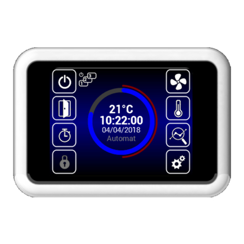
1. Turn the unit ON/OFF
2. Manual start up of Door mode
3. Timer
4. Password lock
5. Ventilation mode settings
6. Required temperature settings
7. Detailed informationof ventilation status
8. Settings
9. Display of current temperature, ventilation rate, CO2
comcentration, ventilation mode and date
9
CONTROL

32 VV. Creating innovative solutions for you and your business since 1995.
ver.1 19-07-21
21 3 4
Warning icons
They inform about errors. Clicking on them opens a screen with the error report.
1. Night reduction
2. Door mode
3. Timer
4. Device cooling
5. Warning icon
5
1. Outside temperature
2. Inlet temperature
3. Room temperature
4. Back to previous screen
5. SP = Temperature setpoint
6. Return water temperature
7. Blocked heating indication (summer mode)
8. Information about the type of unit
9. Green color = active sensor
10. Fan speed
11. Heating power
12. Sub units overview
1
54 7
2
3
6
9
10
11
8
12
iINFORMATION ICONS
CURRENT STATUS

42 VV. Creating innovative solutions for you and your business since 1995.
ver.1 19-07-21
1. Date and time
2. Display backlight
3. Language
4. Airowsettings
5. Timer
6. QR code
7. Service menu
8. Required temperature settings
6
5
7
8
2
1
3
4
1. Displaythecurrentairowstatus
2. Displayrequiredairow(20%steps)
3. Reduceorincreaseopening’sairow(withcloseddoors)
2
2
1
1
3
3
1. Actual temperature at selected sensor in menu 09
2. RequiredoutputManualmode=%Automaticmode=°C
3. Reduce or increase required temperature
SETTINGS MENU
AIR FLOW SETTINGS WITH CLOSED DOORS
REQUIRED TEMPERATURE SETTINGS WITH CLOSED DOORS

52 VV. Creating innovative solutions for you and your business since 1995.
ver.1 19-07-21
1
1. Actiavtion / deactivation of time switch
2. Week regime
3. Year regime
2
3
Touch a day to set ventilation modes
Week mode
Touch to set individual intervals of ventilation (time ON/OFF,
vent. mode, vent. level, temperature)
1. Touch for copying time interval
1
Year mode
Add a time mode
UNIT‘S TIME SWITCH

62 VV. Creating innovative solutions for you and your business since 1995.
ver.1 19-07-21
In manual mode it is possible to set the desired temperature
and fan power.
In automatic mode only the desired temperature may be set.
1. Beginning of time interval (Day/Month)
2. End of time interval (Day/Month)
3. Values setting
4. Delete time interval
5. Back
• When the time interval ends, the unit goes into stand-by
mode.
2
4
3
5
1
2
1
1. Display brightness in active mode
2. Display brightness in Standby mode
DISPLAY SETTINGS

72 VV. Creating innovative solutions for you and your business since 1995.
ver.1 19-07-21
TIME AND DATE SETTINGS
1. Scroll up and down on the numbers to set the date and
time
LANGUAGE SETTINGS

82 VV. Creating innovative solutions for you and your business since 1995.
ver.1 19-07-21
• Use code 1616 to access the service MENU
• This MENU is intended primarily for service technicians or users who have experience with HVAC units. Changes in this
MENUcanleadtoimproperoperationoftheunit.Ifyouareuncertain,rstcontactyoursupplierformoreinformation.
1616
Scroll up/down to select menu then tap on selected menu
Mode01
1. MANUAL or AUTOMAT control
2. Activate/deactivate automatic control of fan speed ac-
cording to temperature
1
2
SERVICE MENU

92 VV. Creating innovative solutions for you and your business since 1995.
ver.1 19-07-21
1. Door contact (NO/NC)
2. External control contact (NO/NC)
3. Error contact (NO/NC)
4. Ad 1)
5. Ad 2).
6. Ad 3)
02
4
5
6
3
2
1
Ad 1) – External temperature sensor activation/settings
Options:
None – no sensor connected – inactive
EXT-1 (45,46) – sensor connected (must be on
terminals 45 y 46)
BMS – sensor active and used from the master system
Ad 2) - Sets the external contact input behaviour. Options:
None – inactive
External control – External switching of device
Night reduction–Nightreductionon/o(settings
described below)
Ad 3) - Thermostat (NO/NC)
Filter timer06
3
2
1
1. Enableltertimer
2. Set the time after which a notice will appear in the main
screen. 1000h ~ 5000h
3. Current timer status
4. RESETbutton(useafterreplacinglters)
Usethismenutosettheperiod(inmotorhours)afterwhichyouwillberemindedtoreplacetheltersorresettotimer.
4
HW setting

10 2 VV. Creating innovative solutions for you and your business since 1995.
ver.1 19-07-21
08
09
Available only in automatic mode
Use this menu to select the sensor to be used for primary temperature control
Options:
Outlet – Temperature sensor at the outlet (behind the
exchanger)
Inlet – Temperature sensor at the inlet (before the
exchanger)
Room – Room temperature sensor
Thermostat – Room thermostat (ON/OFF)
Room BMS – Room temperature recieved from building
management system
Automatic mode. Manual mode.
Temperature sensor

11 2 VV. Creating innovative solutions for you and your business since 1995.
ver.1 19-07-21
Setting the regulation characteristics If regulation is variable
or inconsistent. This setting may be carried out solely fo-
llowing consultation with the manufacturer.
08 PID parameters
17
08
20
The MODBUS menu is used to set the Modbus communica-
tion.
Modbus RTU

12 2 VV. Creating innovative solutions for you and your business since 1995.
ver.1 19-07-21
1. User security level
2. Numeric password to unlock
Several security levels can be chosen for possible password-
-free operation:
Activate/Deactivate - Enables activation and deactivation of
the unit without password
Activate/Deactivate, Temperature, Flow - Enables activa-
tion
and deactivation of the unit, setting required temperature,
and ventilation power without password
Temperature, Flow - Enables setting the desired temperatu-
re and ventilation power without password
Full - Does not enable any settings without entering password
User mode - Enables the unit to be operated per the following
screen:
After entering the password, the unit can be fully operated
and set
08
23
1
2
User lock

13 2 VV. Creating innovative solutions for you and your business since 1995.
ver.1 19-07-21
08
28
2
1
4
3
1. Enable/disable function
2. Start of winter period (month number)
3. End of winter period (month number)
4. Temperature limit – the heating is disabled if the tem-
perature on the “Outdoor” sensor is higher than the one
set here
08 Night Reduction29
2
1
4
3
1. Setting start time for reduced temperature
2. Setreducedtemperatureperiodstart(range-1~-5°C)
3. Set reduced temperature period end
4. Enable / disable function
Use this menu to set heating limits in summer months.
If the outside temperature sensor is not set, the “summer
heating” mode will operate only according to the selected
time and the temperature will not be taken into account
This MENU allows for setting reduced temperatures during
night hours with closed doors.
In this menu, the reduction of temperature may be set
onlybyvedegreesatthesettimecomparedtothe
set (required) temperature.
Summer heating

14 2 VV. Creating innovative solutions for you and your business since 1995.
ver.1 19-07-21
08
30
2
1
3
1. Enable/disable function
2. Fixed-xedsetting/Selearning-automationmenu
3. Setting Fixed mode
This MENU allows setting of behaviour of the regulator accor-
ding to door contact
1. Settingofowrwithopendoors
2. Required temperature with open doors
3. Overrun mode: at a set time, or upon achieving a spe-
cictemperature
1. Air curtain operation time at minimum fanr speed from
door closing
1. Air curtain operation time at maximal fan speed from
door closing
2
1
Time interval overrun mode setting
Door contact
2
1
3

15 2 VV. Creating innovative solutions for you and your business since 1995.
ver.1 19-07-21
conditionsforactivationSelearningmode.
1. Fan power while open door
2. The temperature which the heater attempts to reach
while open door.
2
1
In this menu it is possible to specify which sensor will be
active and the temperature the air curtain attempt to reach
after closing doors so as to balance temperature loss.
After reaching the set temperature, the air curtain returns
into the selected automatic/manual mode.
Temperature overrun mode setting
08
30
1. Enable/disable function
2. required temperature with the door open.
2
1
Selearning-availableonlyinautomationandactive
function mode (Auto speed control), depending on the
number of open doors it optimises the period in which the
shutter is in operation, even when doors are closed.
Door contact - Selearning

16 2 VV. Creating innovative solutions for you and your business since 1995.
ver.1 19-07-21
The menu is enabled only in units with water exchanger
08
31
1. Enable/disable function
2. If the air temperature is lower than the set one, the frost
protection will be activated
3. If the water temperature is lower than the set one, the
frost protection will be activated
1
3
2
Water antifreeze

17 2 VV. Creating innovative solutions for you and your business since 1995.
ver.1 19-07-21
1.Number of SLAVE units: 0 ~ 10
2. Use one door contact as main. Its status will be sent to
the SLAVE regulators and it will no longer be necessary to
connect it to each regulator, if required.
Not allowed = the door contact will not transmit to the
SLAVE regulator from the MASTER
Allowed = the door contact will transmit to the SLAVE
regulator from the MASTER
3. Activates the icon in the main screen to turn each SLAVE
regulator ON/OFF. If inactive, all the SLAVE regulators will be
turnedonorosimultaneously
Not allowed = The SLAVE regulators are turned on/
osimultaneously
Allowed = The SLAVE regulators can be turned on/
oindividuallyformthemainscreen
Slave address setting:
ADDRESS SLAVE UNIT ADDRESS SLAVE UNIT
1166
2277
3388
4499
55A10
08
32
1
3
2
Use this menu to set the behaviour of the regulators
connected as SLAVE
Subunits

18 2 VV. Creating innovative solutions for you and your business since 1995.
ver.1 19-07-21
The set limits on fan power restrict the extent of fan control for open and closed door. This restriction is applied to
manual and automatic control of fan power. Exceeding limits in any fan power setting is signalled when the setting ele-
ment turns red with the text “overruns”.
08
33
1
3
21. Enable/disable function
2. Maximum temperature for return water
3. Setting periods for water valve movement.
4. Minimumwaterowcanbesetonlyforanalogcontrol
of the valve.
This MENU is available only for units with water heat ex-
changer it allows for advanced setting of water heat exchang-
er regulation
4
08 Adv. fan setting34
2
1
3
1. The time for which the fan will be operational from the
momentthedesiredtemperatureisachieved+0.3°Con
the ROOM sensor in closed door mode. This setting is
available only when the ROOM temperature sensor is
selected (1616 / Temperature sensor)
2. Setting fan power limits for open doors. Min - Max
3. Setting fan power limits for closed doors.Min - Max
MENU for setting the fan when closing and opening the door.
Allows advanced fan control settings.
Advanced water setting

19 2 VV. Creating innovative solutions for you and your business since 1995.
ver.1 19-07-21
Power reset
Software reset
08
48

20 2 VV. Creating innovative solutions for you and your business since 1995.
ver.1 19-07-21
CAUTION!
Each panel must have its own address, otherwise it may result in the malfunction
of the regulator.
Terminals must be set if multiple panels are to be connected. They are found in the
main electronics and the controller:
Terminal settings
Use this menu to set the remaining parameters
Wiring connection
CP 1 CP 2
ON
ON
CP 1 CP 2
ON
ON
ON
ONOFF
OFF
08
49
1. Sets the CAN address of the control panel so up to 2 con-
trol panels may be connected to the MASTER regulator
Options: CP 1 = control panel’s address is 1
CP 2 = control panel’s address is 2
2. Enable/disable automatic switch of summer/winter time
The address is set for each controler, which then addressed
according to it.
2
1
Other settings
Other manuals for AirGENIO
2
Table of contents
Other 2VV Control System manuals
Popular Control System manuals by other brands

ACC
ACC SmarTouch Digital series User & Programmers Manual

Bosch
Bosch rexroth SYDFED 2X Series manual

Exhausto
Exhausto VEX200 series Basic instructions

Daktronics
Daktronics RC-100 Operation manual

Lutron Electronics
Lutron Electronics RadioRA-SR Setup guide

Ormazabal
Ormazabal cgmcosmos-l General instructions