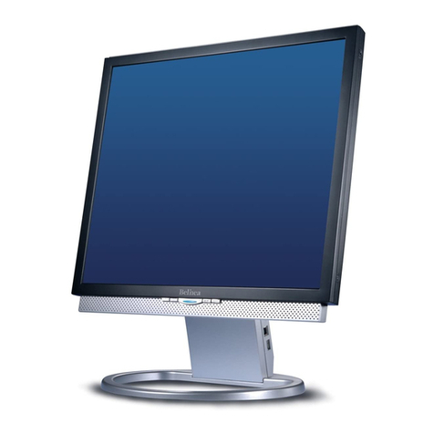
BELINEA 101830 User manual

18" LCD Colour Monitor - Maxdata(101830)
Horizontal frequencies
30-82kHz
Service
Service
Service
TABLE OF CONTENTS
Published by BCU Monitor Printed in Taiwan Copyright reserved Subject to modification Jul . 12 2002
DDC/Power saving/Auto Picture Adjustment
Description Page
Important Safety Notice ---------------------------------- 2
Technical Data ------------------------------------------ 3~4
Connection to PC, Front Control------------------------ 5
Setting using the OSD Menu----------------------------- 6
Failure Mode of LCD Panel-------- -- -------------------- 7
Clock&Phase Adjustments--------------------------------9
OSD Lock/Unlock--- --------------------------------------10
Aging Mode------------------------------------------------- 11
Factory Mode---------------------------------------------- 12
Warning and Notes----------------------------------------13
DDC Hex Data---------------------------------------- 21~22
Wiring Diagram-------------------------------------------- 23
Troubleshooting---------------------------------------------8
DDC Instructions------------------------------------- 14~20
Electrical Instructions-------------------------------- 24~25
Repair Flow Chart-------------------------------------26~28
Block diagram-------------------------------- --------------29
Power Diagram---------------------------------------------30
Power Panel (C.B.A.)-------------------------------------31
Description Page
Video Input Diagram---
Video & SW_DDC Diagram---------------------------- 33
Scaler Diagram------------------------------------------- 34
Frame_Beffer Diagram---------------------------------- 35
LVDS Diagram---------------------------------------------36
MCU Diagram---------------------------------------------37
Scaler Panel (C.B.A.)-------------------------------38~39
Inverter Diagram(AMBIT)-------------------------- 40~41
Inverter Panel(C.B.A.)------------------------------42~43
Control Diagram------------------------------------------44
Control Panel(C.B.A.)-----------------------------------45
Exploded View ------------------------------------------- 46
Recommended
CA110 Application----------------------------------51~59
General Product Specification--------------------61~83
Safety Test Requirements------------------------------84
Important Information-----------------------------------85
--------------------------------- 32
parts list--------------------------------47
Spare parts list-------------------------------------- 48~50
Repair Tips------------------------------------------------60
REFER TO BACK COVER FOR IMPORTANT SAFETY GUIDELINES
CAUTION: USE A SEPARATE ISOLATION TRANSFORMER FOR THIS UNIT WHEN SERVICING.
ANY PERSON ATTEMPTING TO SERVICE THIS CHASSIS MUST FAMILIARIZE HIMSELF WITH THE CHASSIS
AND BE AWARE OF THE NECESSARY SAFETY PRECAUTIONS TO BE USED WHEN SERVICING ELECTRONIC
EQUIPMENT CONTAINING HIGH VOLTAGES.
SAFETY NOTICE
GB 3138 106 10216
DL9B3L/00C
(LG PANEL)

Important Safety Notice
2
FOR PRODUCTS CONTAINING LASER :
DANGER- Invisible laser radiation when open.
AVOID DIRECT EXPOSURE TO BEAM.
CAUTION- Use of controls or adjustments or
performance of procedures other than
those specified herein may result in
hazardous radiation exposure.
CAUTION- The use of optical instruments with this
product will increase eye hazard.
TO ENSURE THE CONTINUED RELIABILITY OF THIS
PRODUCT, USE ONLY ORIGINAL MANUFACTURER'S
REPLACEMENT PARTS, WHICH ARE LISTED WITHTHEIR
PART NUMBERS IN THE PARTS LIST SECTION OF THIS
SERVICE MANUAL.
Proper service and repair is important to the safe, reliable
operation of all Maxdata Company** Equipment. The service
procedures recommended by Maxdata and described in this
service manual are effective methods of performing service
operations. Some of these service operations require the use
of tools specially designed for the purpose. The special tools
should be used when and as recommended.
It is important to note that this manual contains various
CAUTIONS and NOTICES which should be carefully read in
order to minimize the risk of personal injury to service
personnel. The possibility exists that improper service
methods may damage the equipment. It is also important to
understand that these CAUTIONS and NOTICES ARE NOT
EXHAUSTIVE. Maxdata could not possibly know, evaluate
and advise the service trade of all conceivable ways in which
service might be done or of the possible hazardous
consequences of each way. Consequently, Maxdata has not
undertaken any such broad evaluation. Accordingly, a
servicer who uses a service procedure or tool which is not
recommended by Maxdata must first satisfy himself
thoroughly that neither his safety nor the safe operation of the
equipment will be jeopardized by the service method selected.
* * Hereafter throughout this manual, Maxdata
Company will be referred to as Maxdata.
WARNING
Critical components having special safety characteristics are
identified with a by the Ref. No. in the parts list and
enclosed within a broken line*
(where several critical components are grouped in one area)
along with the safety symbol on the schematics or
exploded views.
Use of substitute replacement parts which do not have the
same specified safety characteristics may create shock, fire,
or other hazards.
Under no circumstances should the original design be
modified or altered without written permission from Maxdada.
Maxdata assumes no liability, express or implied, arising out
of any unauthorized modification of design.
Servicer assumes all liability.
* Broken Line
Take care during handling the LCD module with backlight
unit
- Must mount the module using mounting holes arranged in four
corners.
- Do not press on the panel, edge of the frame strongly or electric
shock as this will result in damage to the screen.
- Do not scratch or press on the panel with any sharp objects, such
as pencil or pen as this may result in damage to the panel.
- Protect the module from the ESD as it may damage the electronic
circuit (C-MOS).
- Make certain that treatment person’s body are grounded through
wrist band.
- Do not leave the module in high temperature and in areas of high
humidity for a long time.
- Avoid contact with water as it may a short circuit within the module.
- If the surface of panel become dirty, please wipe it off with a soft
material. (Cleaning with a dirty or rough cloth may damage the
panel.)
Go to cover page
Max 101830

3
Technical Data
Go to cover page
Technical Specifications Pin Assignment
D-Sub connector
Pin No. Assignment
1 Red video input
2 Green video input
3 Blue video input
4 Ground
5 Not connected
6 Red return
7 Green return
8 Blue return
9 + 5v DDC
10 Ground
11 Ground
12 SDA (DDC data)
13 Hor. Sync
14 Vert. Sync
15 SCL (DDC Clock)
The digital/analog DVI-I onnector contains 29 signal contacts
organized in three rows of eight contacts. Signal pin
assignments are listed in the following table:
1
5
6
10
11
15
Pin No. Description
1TMDS data2-
2TMDS data2+
3TMDS data2 shield
4NC
5NC
6DDC clock
7DDC data
8Not connected-
9TMDS data1-
10 TMDS data1+
11 TMDS data1 shield
12 NC
13 NC
14 +5V
15 Ground(return for +5V and H/Vsync)
16 Hot plug detect
17 TMDS data0-
18 TMDS data0+
19 TMDS data0 shield
20 NC
21 NC
22 TMDS clock shield
23 TMDS clock+
24 TMDS clock-
C1 Analog R
C2 Analog G
C3 Analog B
C4 Analog H-sync
C5 Analog Vert. Sync.
1.1 LCD
Type NR. : LM181E05-C3 (LG-Philips)
Outside dimensions : 389(w)317.2(h)27(d) (Typ) mm
Pitch ( mm ) : 0.2805 (per one triad) x 0.2805mm
Color pixel arrangement : RGB vertical stripes
Display surface : low reflection, antiglare with hard coating
Number of color : 256 gray levels(8 bits)
Backlight : CCFL edge light system
Active area(WxH) : 359x287.2mm (18” diagonal)
View angle : Horizontal & Vertical 160 degree (CR>=10)
Contrast ratio : 350:1
White luminance : 250 nits (Typ)
1.2 Scanning frequencies
Hor. : 30 82 K Hz
Ver. : 56 - 76 Hz
1.3 Video dot rate : < 140 MHz
1.4 Power input : 90-264 V AC, 50/60 2 Hz
1.5 Power consumption : < 60 W maximum ( exclude USB option )
1.6 Dimensions : 426 * 454 * 180 mm
1.7 Weight : 8.4 KGS
1.8 Functions :
D-shell analog R/G/B separate inputs, H/V sync separated,
Composite (H+V) TTL level,
DVI digital Panel Link TMDS input
1.9 Ambient temperature : 5 C - 35 C
2 Electrical characteristics
2.1 Interface signals
The input signals can be applied in three different modes :
1). D-shell Analog
Input signal : Video, Hsync., Vsync
Video : 0.7 Vp-p, input impedance, 75 ohm @DC
Sync. : Separate sync TTL level , input impedance 2k2 ohm
terminate
Hor. sync Positive/Negative
Ver. sync Positive/Negative
Composite sync TTL level, input impedance 2k2 ohm terminate
(Positive/Negative)
Sync on green video 0.3 Vp-p Negative (Video 0.7 Vp-p Positive)
2). Intel DVI Digital
Input signal : Single channel TMDS signal
2.1.1 Audio
Input signal level : 500mVrms
Headphone output signal level : 32ohm 0.7+0.7 Vrms
Input signal connector : 3.5 mm mini jack
Loud speaker : 2+2 W stereo firing
2.1.2 Microphone
Sensitivity: -65± 5 dB re 1V/ubar at 1khz
Output impendence : 600 ohm typical
Max 101830

Technical Data(Continued)
4
Go to cover page
Max 101830
Allowed 85 Hz overscan signal mode specified
Once the signal input of PC is 85Hz, this monitor is able to display
at least for 10 minutes . An attention signal appears and shows
“This is 85Hz overscan for 5 seconds, change computer display
input to 1024X768 @ 60 Hz “
Dot rate (MHz) H.freq (KHz) Mode Resolution V.freq (Hz)
36.000 43.269 VESA 640 * 480 85.008
56.250 53.674 VESA 800 * 600 85.061
94.500 68.677 VESA 1024 * 768 84.997
Input signal mode
Factory preset 16 modes (F)
PRESET VIDEO RESOLUTION
Pre-set 32 modes (P)
PRESET VIDEO RESOLUTION
Power management
The power consumption and the status indication of the set
with power management function are as follows,
Note : Disconnect DVI signal cable and audio module.
STATUS Horizontal Vertical Power Spec LED
On Pulse Pulse as normal on Green
Stand-by No Pulse Pulse < 2 W Amber
Suspend Pulse No Pulse < 2 W Amber
off No Pulse No Pulse < 2 W Amber
According to VESA power saving signaling.
TCO99 power saving requirement
EPA energy star requirement
(Power Switch Off)
for Digital input power consumption is less 2W
( In non-DMPM recoverable off mode)
# Resolution Frequency Pixel rate Sync Comment
1 640X350 31.5K/70HZ 25.175 (+/-) IBM VGA 10h
2 720X400 31.5K/70HZ 28.322 (-/+) IBM VGA 3h
3 640X480 37.5K/75HZ 31.501 (-/-)
4 640X480 35.0K/67HZ 30.24 (-/-)
5 640X480 31.5K/60HZ 25.175 (-/-)
6 800X600 35.2K/56HZ 36 (+/+)
7 800X600 46.9K/75HZ 49.498 (+/+)
8 800X600 37.9K/60HZ 40 (+/+)
9 832X624 49.7K/75HZ 57.28 (+/+) MAC
10 1024X768 60.0K/75HZ 78.75 (+/+)
11 1024X768 48.4K/60HZ 65 (-/-)
12 1152X870 68.7K/75HZ 100 (-/-) MAC
13 1152X900 71.8K/76HZ 108 (+/+) SUN Mode II
14 1280X1024 64.0K/60HZ 108 (+/+)
15 1280X1024 80.0K/75HZ 135 (+/+)
16 688X556 31.3K/50HZ 27 (-/+) TV-PAL
#Resolution Frequency Pixel rate Sync Comment
1 640X350 31.5K/70HZ 25.175 (+/-) IBM VGA 10h
2 720X400 31.5K/70HZ 28.322 (-/+) IBM VGA 3h
3 640X480 37.5K/75HZ 31.501 (-/-)
4 640X480 43.3K/85HZ 36 (-/-)
5 640X480 37.9K/72HZ 31.5 (-/-)
6 640X480 35.0K/67HZ 30.24 (-/-)
7 640X480 31.5K/60HZ 25.175 (-/-)
8 800X600 35.2K/56HZ 36 (+/+)
9 800X600 46.9K/75HZ 49.498 (+/+)
10 800X600 37.9K/60HZ 40 (+/+)
11 800X600 53.7K/85HZ 56.251 (+/+)
12 832X624 49.7K/75HZ 57.28 (+/+) MAC
13 800X600 48.1K/72HZ 50 (+/+)
14 1024X768 60.0K/75HZ 78.75 (+/+)
15 1024X768 48.4K/60HZ 65 (-/-)
16 1024X768 56.5K/70HZ 75 (-/-)
17 1024X768 61.1K/76HZ 83.096 (+/+) IBM XGA-2
18 1024X768 68.7K/85HZ 94.5 (+/+)
19 1152X864 67.5K/75HZ 108 (+/+)
20 1152X864 63.9K/70HZ 94.5 (+/+) non-VESA
21 1152X864 54.0K/60HZ 79.9 (+/+) non-VESA
22 1152X870 68.7K/75HZ 100 (-/-) MAC
23 1152X900 61.8K/66HZ 92.94 serr- SUN Mode IV
24 1152X900 71.8K/76HZ 108 (+/+) SUN Mode II
25 1280X960 60.0K/60HZ 108 (+/+)
26 1280X960 75.0K/75HZ 129.895 (+/+) non-VESA
27 1280X1024 76.0K/72HZ 130.223 (+/+) DOS/V
28 1280X1024 64.0K/60HZ 108 (+/+)
29 1280X1024 80.0K/75HZ 135 (+/+)
30 1280X1024 81.1K/76HZ 135.008 (-/-) SUN Mode I
31 1280X1024 71.7K/67HZ 117 (+/+) SUN Mode V
32 688X556 31.3K/50HZ 27 (-/+) TV-PAL

Connection to PC,Front Control 5
Go to cover page
Connecting cables to the monitor
The monitor ports are protected by a cover.
1 = Power connector
2 = DVI-I connector
3 = D-SUB connector
The data cable supplied has two 15-pin D-SUB connectors for
the D-SUB connector of the monitor and of the computer.
Connect one of the D-SUB connectors of the data cable to the
D-SUB connector on the monitor (3) and secure the plug-in
connection by tightening the safety screws.
If instead of the data cable supplied you want to use a data cable
with DVI-I connector or if you want to connect the monitor to a
second computer, proceed as follows:
Connect the DVI-I connector of the data cable to the DVI-I
connector on the monitor (2) and secure the plug-in connection by
tightening the safety screws.
Data cables with DVI-I connectors are available from specialised
dealers.
After switching on the monitor you must select the desired input
with the OSD menu .
Switching the monitor on/off
The ON/OFF switch (1) is used for switching the monitor on and
off.
The power indicator (2) glows green when the monitor and
computer are switched on. The power indicator glows orange
when the monitor does not receive a video signal or is in the
energy-saving mode. The power indicator goes off when the
monitor is switched off.
3~8 = Buttons for the OSD menu(On-Screen-Display)
2 = Power indicator
1 = Power button
Monitor settings with the buttons of the control panel
With the buttons of the control panel, you can make the following
settings directly: auto-adjustment of the monitor, adjusting the
brightness and adjusting the contrast.
Other settings are carried out via an integrated OSD menu (On-
Screen Display).
Performing auto-adjustment of the monitor
Press the AUTO button.
The picture quality ( , ) and picture position will be
optimally adjusted for your system.
Press the MENU button to save the settings.
The brightness of the monitor is adjusted directly with the arrow
buttons.
PHASE CLOCK
Adjusting the brightness
Press the button or .
BRIGHTNESS
Press the or button to adjust
the brightness.
The setting window disappears after
approximately 60 seconds if no
further setting is made.
All changes are stored automatically.
BRIGHTNESS
50
The window with a setting scale is visualised.
Removing the monitor base
The monitor surface is susceptible to scratching!
Lay the monitor on its face on a soft surface.
Remove the four screws on the rear of the monitor.
123
Max 101830

Settings using the OSD menu
6
With the buttons on the control panel, call up and use the
integrated OSD (On-Screen Display) menu.
The OSD menu is available in different languages. The English
menu names are used in the following description (default setting).
With the OSD function you can select another
language.
The main menu appears on the screen with icons for the setting
functions.
LANGUAGE
The first symbol ( ) is
highlighted.
If necessary, press the or
button to mark another icon (e.g.
).
Press the MENU button to select
the highlighted icon.
LANGUAGE
ADJUST POSITION
Press the or button to
adjust the selected function
(here: HORIZONTAL).
Press the key or to
mark another function or press
the MENU key to return to the
main menu.
Select the symbol (EXIT
MAIN CONTROLS) in the
main menu and press the MENU
key to exit the OSD menu.
The corresponding setting window (here: )
is displayed.
ADJUST POSITION
Setting language for the OSD menu
Adjusting picture position
?
Calling the ADJUST POSITION setting window
Horizontal picture position ( HORIZONTAL
the picture to the left or to the right
Vertical picture position ( VERTICAL ): Shifting
the picture down or up
): Shifting
Adjusting the brightness and contrast
Calling the BRIGHTNESS & CONTRAST setting window
Setting the brightness of the display(BRIGHTNESS)
Setting the contrast of the display ( CONTRAST )
Setting the colour temperature
The "warmth" of the screen colours is set using the colour
temperature. The colour temperature is measured in K (= Kelvin).
Setting the picture quality
Eliminating picture interference (VIDEO NOISE )
Eliminating picture noise and horizontal interference
(PHASE)
Eliminate vertical interference with local fuzziness
(CLOCK)
Calling the ADJUST COLOR setting window
ORIGINAL PANEL COLOR = Setting for general
applications (default setting)
9300K FOR CAD/CAM = Setting for CAD/CAM programmes
6500K FOR IMAGE MANAGEMENT = Setting, for example,
for image processing or playing DVDs
USER PRESET = User -defined setting
In the user -defined setting you can change the colour
ratios of the basic colours (red, green, blue) as required.
Setting position for the OSD menu
Calling the OSD SETTINGS setting window
You can shift the OSD menu up, down, to the left or to the
right.
Displaying monitor data
You will find the serial number and the current resolution
of this screen in PRODUCT INFORMATION
.
i
Activating the factory settings
Activating the factory settings(RESET TO FACTORY
NO = retain own settings
YES = Activating the factory settings
WithYES all monitor settings are reset to the factory settings.
SETTINGS)
Selecting input signal
The monitor can be operated with analog or digital signals. Withthis
function you can (depending on the graphics card you use) switch over
between the analog and the digital mode.
Calling the INPUT SELECTION setting window
Switch on the analog mode ( ANALOG DSUB ).The monitor
processes the signals of the analog port (VGA/D
-SUB).
Switch on the digital mode ( DIGITAL DVI ). The monitor
processes the signals of the digital port (DVI-I).
Switch on analog mode via digital port ( ANALOG DVI ).
The monitor processes the analog signals of the digital
port (DVI -I).
Locking the OSD menu (OSD Lock)
The OSD menu can be locked to prevent accidental or
unauthorised changes to the monitor settings.
Press the MENU button and hold it for approx. 10 seconds.
Please proceed in the same manner to release the locked OSD
menu again.
Setting language for the OSD menu ( )
You can choose from English (default setting), German,
French, Spanish, Italian, and Japanese.
LANGUAGE
Go to cover page
Max 101830

7
Go to cover page
Max 101830
Failure Mode of LCD panel
Quick reference for failure mode of LCD panel
This page presents problems that could be made by LCD panel. It is
not necessary to repair circuit board. Simply follow the Mechanical
instruction o n this manual to eliminate failure by replace LCD panel
or backlight tubes.
Failure description Phenomenon
Vertical dim lines
Vertical block defect
Vertical lines defect
(Always bright or dark)
Horizontal block defect
Horizontal dim lines
Horizontal lines defect
(Always bright or dark)
Has bright or dark pixel
.
..
.
.
.
.
..
.
.
.
Bright pixel
Dark pixel
..
....
Polarizer has bubbles
Polarizer has bubbles
Foreign material inside
polarizer. It shows linear or
dot shape.
....
Concentric circle formed
Bottom back light of LCD is
brighter than normal
Backlight un-uniformity
Backlight has foreign
material. Black or white
color, linear or circular type

8Trouble Shooting
Go to cover page
Trouble shooting
Should an error occur, first check the following points. If the distortion is still not eliminated, the monitor should, if possible,
be checked on another computer and/or with another data cable.
Having this problem? Check the following points:
No display (power indicator does
not light)
Check whether the monitor is
switched on.
Check whether the power cable
on themonitor is connected
correctly.
Check whether the computer is
switched on.
Having this problem? Check the following points:
No display (power indicator lights) Check whether the computer is
switched on.
Check whether the data cable for
the monitor is
correctly attached
to the monitor port on the computer.
Press any key on the computer
keyboard the computer may be in
Alter the brightness and/or contrast
until you get apicture.
Check whether the data cable for
the monitor is correctly attached to
the monitor port on the computer.
Check whether the computer is
switched on.
The input signal (horizontal
frequency and refresh rate) at the
displayed input does not correspond
to the technical monitor data.
Adjust the video frequency range
using the computer sof tware (safe
Picture position is not correct The monitor recognises an
undefined mode (see
").
Press the AUTO button to conduct
the
Technical
data
auto-adjustment of the screen.
Set the picture position with the
OSD menu .
Picture is shaking Check whether the data cable for
the monitor is correctly attached to
the monitor port on the computer.
Having this problem? Check the following points:
Picture disturbances (vertical lines) Press the AUTO button to conduct
the auto-adjustment of the screen.
Set the picture quality in VIDEO
NOISE(CLOCK ).
Picture disturbances (horizontal
lines, picture noise) Press the AUTO button to conduct
the auto -adjustment of the screen.
Set the picture quality in VIDEO
NOISE(PHASE ).
The screen becomes darker The background lighting has a
limited lifetime.If your monitor
display should become too dark,the
exchanged.
background lighting will have to be
Image of last screen display still
visible
If you switch from a high
-contrast
display (for example black lines/
characters on a white background)
to a picture of medium brightness,
you may be able to see a faint
image of the previous display for a
time. This phenomenon is not due
to a monitor defect but to the
technology used (IPS display with
large viewing angle, IPS = In Plane
Switching).
Permanently unlit or lit pixels The standard of production
techniques today cannot guarantee
an absolutely fault -free screen
display. A few isolated constant lit
or unlit pixels may be present.
The maximum permitted number
of pixels faults is stipulated in the
stringent international standard
ISO 13406 -2 (Class II).
Example: a 17" or 18" flat- screen
monitor with a resolution of
1280 x 1024 has 1280 x 1024 =
1310720 pixels.
Each pixel consists of three
subpixels (red, green and blue), so
there are almost 4 million dots in
total.
According to ISO 13406-2 (Class II),
a maximum of 6 pixels and 7
subpixels may be defective, i. e.
a total of 25 faulted dots.
This corresponds to approx.
0,0006 % of the entire screen
surface!
energy saving mode.
Mode ) or Using another CRT
monitor.
Max 101830

CLOCK & PHASE Adjustments 9
Step 1 : Click on the Start button (Win95, Win98 or Win NT)
and choose " Shut Down...". as shown in Fig. 2.
Step 2 : The menu of " Shut Down Windows " is as shown in Fig. 3
Step 3 : Retain Shut Down Window on the screen , follow
the CLOCK and PHASE adjustment instructions for the
optimal video display.
PHASE phenomenon
Due to the different quality of video signal generated from graphics
cards. By press AUTO button for
t is necessary to adjust
CLOCK and PHASE functions for the optimal video display of LCD
monitor by manual. Following steps will guide you to make correct
adjustment of CLOCK and PHASE.
However, CLOCK and PHASE functions are only available while analog
video signal is supplied. Operating unit under digital signal state, the
video clock information can be obtained from graphics cards directly.
Therefor, it is unnecessary to adjust these functions.
CLOCK and PHASE adjustment
automatically. Sometimes, the deviation of video signal which generated
from graphics cards is out of control, then i
Manual adjustment
If the quility of display still poor or flicker, you may also improve it by
manual adjust CLOCK and PHASE functions to eliminate the flicker.
Step 4 : Press the MENU button to bring up MAIN CONTROLS
(OSD menu).
Step 8 : Press or to adjust PHASE. The picture will
be adjusted as following figure, adjust PHASE and check the
picture, stop at the point that without any vertical jitter bar
remaining on the screen.
button
Step 5 : Select Video Noise by press button.
Step 6 : Press to bring up it s submenu.button
Step 7 : Press or to adjust CLOCK. The picture will
be adjusted as following figure, adjust CLOCK to fine-tune the
video until optimal display is obtained.
button
Step 9 : Quit OSD menu by press button to save the settings.
CLOCK Phenomenon
Video Noise
(Auto adjustment hotkey)
Front control panel
1 = Buttons for the OSD menu (On-Screen-Display)
2 = Power indicator
3 = Power button
23
1
AUTO MENUINPUT
AUTO button
MENU
MENU
MENU
The monitor has build-in a auto adjustment hotkey on the front panel,
you may obtained a optimal video display by simply press the
button and save the settings. CLOCK, PHASE, Vertical position, and
Horizontal position are adjusted automatically.
AUTO
Fig. 1
Fig. 2
(Before)
(Before)
(After)
(After)
Fig. 3 (Win 98)
MENU
MENU
Go to cover page
Max 101830

10
OSD Lock/Unlock, Attention signal, Service Mode
Go to cover page
Front control panel
ATTENTION
OSD MAIN CONTROLS LOCKED
ATTENTION
OSD MAIN CONTROLS UNLOCKED
ATTENTION
ATTENTION SIGNAL OFF
ATTENTION
ATTENTION SIGNAL ON
To Lock/Unlock OSD function (User Mode)
The OSD function can be locked by pressing button for more than
10 seconds, the screen shows following windows for 3 seconds.
Everytime when you press or button, this message appears
on the screen automatically. The & (brightness) ,
(input) hotkey are still functional for brightness and input signal
selection while OSD locked.
Switch ON/OFF attention signals (User Mode)
All attention signals can be by keep pressing button
for more than 10 seconds if there is no video signal supplied.
Step 1: Disconnect signal cable (Monitor & PC are still ON.)
Step 2: Press "AUTO" button for more than 10 seconds, bring up
message as below.
switched off
Recover attention signals by pressing button for more than 10
seconds without video signal input.
Step 1: Disconnect signal cable (Monitor & PC are still ON.)
Step 2: Press "AUTO" button for more than 10 seconds again,
bring up message as below.
Access Service Mode (in USER MODE)
Method 1:
Leave service mode by either re-feed video signal or simply turn off
and on the power of monitor.
Step 1: Disconnect signal cable on Rear side of monitor.
Don't disconnect signal cable on PC side, because CPU will
detect pin-9 of D-SUB (15 pin connector).
(Monitor & PC are still ON.)
Bring up "CHECK CABLE CONNECTION" screen.
Step 2: Press MENU" " button for more than 15 seconds.
Bring up message as below.
Access Service Mode (in USER MODE)
Method 2:
Leave service mode by either re-feed video signal or simply turn off
Step 1:
- Turn off monitor.
- Disconnect signal cable on PC side.
- Turn on monitor.
(After 3 seconds)
Bring up "NO VIDEO INPUT"
Step 2: Press MENU" " button for more than 15 seconds.
Bring up "SERVICE MODE".
Access Service Mode (in USER MODE)
Method 3:
Leave service mode :simply turn off and on the power of monitor.
Step 1:
-PCoff.
- Signal cable connect to rear side of Monitor only.
- Turn on monitor.
Bring up "NO VIDEO INPUT"
Step 2: Press MENU" " button for more than 15 seconds.
Bring up "SERVICE MODE".
AUTO
AUTO
AUTO
MENU
MENU
Locked OSD function can be released by pressing button for
more than 10 seconds again. While press "MENU" button for OSD
unlocked purpose, the screen will keep showing OSD MAIN
CONTROLS LOCKED u ntil OSD function unlocked and screen
automatically shows following window for 3 seconds.
MENU
1 = Buttons for the OSD menu (On-Screen-Display)
2 = Power indicator
3 = Power button
23
1
AUTO MENUINPUT
INPUT
ATTENTION
CHECK CABLE CONNECTION
ATTENTION
NO VIDEO INPUT
ATTENTION
NO VIDEO INPUT
MENU
MENU
SERVICE MODE
SERIAL NO. : YEKA105542
HOURS OF OPERATION: 000222
MENU
SERVICE MODE
SERIAL NO. : TW211P0022
HOURS OF OPERATION: 000205
SERVICE MODE
SERIAL NO. : TW211P0022
HOURS OF OPERATION: 000205
Max 101830

11
Go to cover page
AGING Mode
Bring up :
After 15 seconds, bring up :
After 15 seconds, bring up :
After 15 seconds, bring up :
----------
----------
repeatly
Connect signal cable again => go back to normal display.
Front control panel
Access Aging.. Mode (Method 1)
(Monitor & PC are ON for Step 1.)
Step 1: Disconnect signal cable on Rear side of monitor.
Bring up "CHECK CABLE CONNECTION" screen.
or
Disconnect signal cable on PC side.
Bring up "ENTERING SLEEP MODE" about 3 seconds,
then disappear.
Step 2:
Turn off LCD monitor.
Push AUTO " " & " " & " " buttons simultaneously
,then release Power buttun only, untill picture comes on the screen.
Bring up "AGING ...".
1 = Buttonsfor the OSDmenu (On-Screen-Display)
2 = Power indicator
3 = Power button
23
1
AUTO MENUINPUT
ATTENTION
CHECK CABLE CONNECTION
ATTENTION
ENTERING SLEEP MODE
AUTO
A G I N G. . .A G I N G. . .
A G I N G. . .A G I N G. . .
Method 2:
Leave AGING mode :connect signal cable to PC,
then turn on PC.
Step 1:
- PC off and Monitor off.
- Signal cable connect to rear side of Monitor only.
- Connect Power Cord to rear side of monitor, then insert the plug
into a properly grounded electrical outlet.
(Power LED of monitor is off now.)
Step 2:
Push AUTO " " & " " & " " buttons simultaneously
,then release Power buttun only, untill picture comes on the screen.
Bring up "AGING ...".
---------
---------
repeatly
AUTO
A G I N G. . .A G I N G. . .
Max 101830

12
Go to cover page
Factory Mode
Access Factory Mode
Factory Mode:
How to Get into Factory Mode Menu
Turn off LCD monitor.
Push AUTO " " & " " & " " buttons simultaneously
,then release Power buttun only, untill picture comes on the screen.
Press MENU " " button, bring up Factory mode indication as
shown in Fig 2.
Fig. 2
Factory Mode indication==>
MAXDATA 180P V1.88 02-04-17
Contrast adjustment (Sub-Contrast). Use this menu item to
adjust the contrast gain of pre-amp ranges from 0 to 255.
(For
9 3 0 0 K R G B
6 5 0 0 K R G B
Color temperature gain adjustment. Use these menu items to
adjust the RGB gains of pre-amp for different color
temperatures, ranges from 0 to 255.
OFFSET R G B
Sub-Brightness adjustment. Use this menu item to adjust
the brightness level (DC-level) of pre-amp range from 0 to
255.(R/G/B ANALOG DC -level).
example: of Sub-Contrast in factory mode is
preset for 100%(Maximum Value) of Contrast Value in user
mode).
GAIN R G B
R/G/B GAIN adjustment. Use this menu item to adjust
the R/G/B (GAIN) of Amp. range from 0 to 255.(R/G/B
ANALOG GAIN Values).
AUTO SUB:
AUTO Colour to Adjust OFFSET R/G/B & GAIN R/G/B
automatically by LCD MONITOR CPU.
RESERVE1: NO FUNCTIONED, RESERVED ONLY.
RESERVE2: NO FUNCTIONED, RESERVED ONLY.
RESERVE3: NO FUNCTIONED, RESERVED ONLY.
AUTO SUB:
Use button to select factory adjustment indication (for example:
MAXDATA 180P V1.88 02-04-17), which is the entrance of the factory
adjustment menu, press MENU " " button to access it. The
window shows as below.
(PS: The “Offset R G B” function can be used on reduce or eliminate
snowy noise on the background when the resolution of video signal is
1280 X 1024 vertical 60Hz. Slightly increase or decrease the value
until snowy noise completely disappear.)
Default values (example) are as below.Default values (example) are as below.
Leave Factory Mode
Turn off monitor, then turn on monitor again => go back
to User mode directly.
Leave Factory Mode
Turn off monitor, then turn on monitor again => go back
to User mode directly.
SUB BRI:SUB BRI:
-
-
OKOK
255255
255255
-
SUB CON:SUB CON:
NO FUNCTIONED,”DIGITALDC-Level” RESERVED
for LCD MONITOR 150P usage ONLY.
AUTO
MENU
Fig. 1
1 = Buttonsfor the OSDmenu (On-Screen-Display)
2 = Power indicator
3 = Power button
23
1
AUTO MENUINPUT
MENU
9300K R G B9300K R G B
6500K R G B6500K R G B
OFFSET R G BOFFSET R G B
SUB CON:SUB CON:
SUB BRI:SUB BRI:
-
-
AUTO SUB:AUTO SUB:
-
OKOK
GAIN R G BGAIN R G B
RESERVE1:RESERVE1:
RESERVE3:RESERVE3:
RESERVE2:RESERVE2:
MAXDATA 180P V1.88 02-04-17
0000
Fig. 3
AUTO
Use or buttons to select SUB-CON, 9300K R G B,..etc.
Use or buttons to decrease/increase the value of each item.
Press " " => go back to MAIN CONTROLS.
All the default values are invisible. Press " " => appear.
To press AUTO " " button on this screen, the values of
OFFSET and GAIN will be adjusted by CPU automatically.
MENU
9300K R G B9300K R G B
6500K R G B6500K R G B
OFFSET R G BOFFSET R G B
SUB CON:SUB CON:
SUB BRI:SUB BRI:
-
-
AUTO SUB:AUTO SUB:
-
OKOK
GAIN R G BGAIN R G B
RESERVE1:RESERVE1:
RESERVE3:RESERVE3:
RESERVE2:RESERVE2:
MAXDATA 180P V1.88 02-04-17
0000
8484
188188
5050
182182
8686
181181
8383
251251
228228
255255
252252
255255
205205
255255
255255
226226
Max 101830

13
Go to cover page
Warning and Notes
Fig.1
V
Warnings
1. Safety regulations require that the unit should be returned
in its original condition and that components identical to
the original components are used. The safety components
are indicated by the symbol .
2. In order to prevent damage to ICs and transistors, all
high-voltage flash-overs must be avoided. In order to
prevent damage to the picture tube, the method shown
in Fig. 1 should be used to discharge the picture tube.
Use a high-voltage probe and a multimeter (position DC-V).
Discharge until the meter reading is 0 V (after approximately
30 seconds).
3. ESD
All ICs and many other semiconductors are sensitive to
electrostatic discharges (ESD). Careless handling during
repair can drastically shorten their life. Make sure that
during repair you are connected by a pulse band with
resistance to the same potential as the ground of the unit.
Keep components and tools also at this same potential.
4. When repairing a unit, always connect it to the AC Power
voltage via an isolating transformer.
5. Be careful when taking measurements in the high-voltage
section and on the picture tube panel.
6. It is recommended that saferty goggles be worn when
replacing the picture tube.
7. When making adjustments,use plastic rather than metal tools.
This will prevent any short-circuit or the danger of a
circuit becoming unstable.
8. Never replace modules or other components while the
unit is switched on.
9. Together with the defleciton unit, the picture tube is used
as an integrated unit. Adjustment of this unit during repair
is not recommended.
10. After repair, the wiring should be fastened in place with
the cable clamps.
11. All units that are returned for service or repair must pass
the original manufactures safety tests.
Notes
1. The direct voltages and waveforms are average voltages.
They have been measured using the Service test software
and under the following conditions :
- Mode : 640 * 480 (31.5kHz / 60Hz)
- Signal pattern : grey scale
- Adjust brightness and contrast control for the
mechanical mid-position (click position)
2. The picture tube panel has printed spark gaps.
Each spark gap is connected between an electrode of the
picture tube and the Aquadag coating.
3. The semiconductors indicated in the circuit diagram(s)
and in the parts lists are completely interchangeable per
position with the semiconductors in the unit, irrespective
of the type indication on these semiconductors.
(CRT ONLY)
Max 101830

DDC Instructions
General
Pin assignment
1
10
6
11 15
5
Assignment Assignment
Pin No. Pin No.
Ground
No Connected
Ground
Blue video input
2
7
6
8
4
5
3
19
12
11
14
13
15
10
Red video ground
Blue video ground
Green video ground
+5V
Ground
Data clock line(SCL)
V.Sync(VCLK for DDC)
H.Sync
Serial data line(SDA)
Green video input
Red video input
A. 15-pin D-Sub Connector
DDC Data Re-programming
In case the DDC data memory IC or main EEPROM which storage all
factory settings were replaced due to a defect, the serial numbers have
to be re-programmed.
It is advised to re-soldered DDC IC and main EEPROM from the old
board onto the new board if circuit board have been replaced, in this
case the DDC data does not need to be re-programmed.
Additional information
Additional information about DDC (Display Data Channel) may be
obtained from Video Electronics Standards Association (VESA).
Extended Display Identification Data(EDID) information may be also
obtained from VESA.
DDC EDID structure
For Analog interface: Standard Version 3.0
Structure Version 1.2
For Digital inferface: Standard Version 3.0
Structure Version 1.3
System and equipment requirements
1. An i486 (or above) personal computer or compatible.
2. Microsoft operation system Windows 95/98.
3. EDID301.EXE program (3138 106 10103) as shown in Fig. 1
4. A/D Alignment kits (3138 106 10079):
inclusion : a. Alignment box x1 (as Fig. 2)
b. Printer cable x1
c. (D-Sub) to (D-Sub) cable x1
d. (DVI-D) to (D-Sub) cable x1 (as Fig. 3)
Note: The EDID301.EXE (Release Version 1.58 20000818)is a
windows-based program, which cannot be run in MS-DOS.
Diskette with EDID301.EXE
EDID301.EXE
Ver:1.58
(DVI-D) to (D-Sub) cable
Note: The alignment box has already build-in a batteries socket for
using batteries (9V) as power source. Pull out the socket by
remove four screws at the rear of box. Please do not forget that
remove batteries after programming. The energy of batteries can
only drive circuits for a short period of time.
To Monitor
DC 8V~12V
Video CardVideo Card
To Printer
Power
indicator
A/D Alignment Kits - Analog connectionA/D Alignment Kits - Analog connection
A/D Alignment Kits - Digital connectionA/D Alignment Kits - Digital connection
Fig. 2Fig. 2
Fig. 1Fig. 1 Fig. 3Fig. 3
To Monitor
(Digital port)
DC 8V~12V
To Printer
Power
indicator
14
Go to cover page
Max 101830

Go to cover page
15
DDC Instructions (Continued)
Step 3: Installation of EDID301.EXE
Method 1: Start on DDC program
Start Microsoft Windows.
1. Insert the disk containing EDID301.EXE program into floppy disk
drive.
2. Click , choose Run at start menu of Windows 95/98 as
shown in Fig. 4.
Fig. 4
4. Click OK button. The main menu appears (as shown in Fig. 6).
This is for initialize alignment box.
Fig. 6
Fig. 5
Fig. 7
Note 1: If the connection is improper, you will see the following error
message (as shown in Fig. 7) before entering the main menu.
Meanwhile, the (read EDID) function will be disable. At this time,
please make sure all cables are connected correctly and fixedly,
and the procedure has been performed properly.
3. At the submenu, type the letter of your computer's floppy disk drive
followed by :EDID301 (for example, A:\EDID301, as shown in Fig. 5).
Method 2: After create a shortcut of EDID301.EXE
: Double click EDID301 icon (as shown in Fig. 8) which is
on the screen of Windows Wallpaper.
Bring up main menu of EDID301 as shown in Fig. 9.
This is for initialize alignment box.
Fig. 9
Note 2: During the loading, EDID301 will verify the EDID data which just
loaded from monitor before proceed any further function, once
the data structure of EDID can not be recognized, the following
error message will appear on the screen as below. Please
confirm following steps to avoid this message.
1. The data structure of EDID was incorrect.
2. DDC IC that you are trying to load data is empty.
3. Wrong communication channel has set at configuration setup
windows.
4. Cables loosed or poor contact of connection.
Fig. 8
1
Configuration and procedure
There are 2 chips contained OSD string, serial number..etc
on the circuit board,
main EEPROM which storage all factory settings,OSD string.
DDC IC which storage 128byte EDID data(serial number ..etc.).
Following descirptions are the connection and procedure for Analog
and Digital DDC application, the main EEPROM can be
re-programmed along with Analog/Digital IC by enable “factory memory
data write” function on the DDC program (EDID301.EXE).
Initialize alignment box
In order to avoid that monitor entering power saving mode due to
sync will cut off by alignment box, it is necessary to initialize
alignment box before running programming software
(EDID301.EXE). Following steps show you the procedures and
connection.
Step 1: Supply 8~12V DC power source to the Alignment box by
plugging a DC power cord or using batteries.
Step 2: Connecting printer cable and video cable of monitor as Fig. 3
Fig. 3
Rear view of hp L1815
12 3
1=Power connector
2=DVI-I connector
3=D-SUB connector
~
~
PC
To printer port (LTP1)
DC Power
8~12 V
Printer
Port
To video card
To
Monitor
To PC
Max 101830

16
Go to cover page
DDC Instructions (Continued)
Max 101830
Re-programming Analog DDC IC
Step 1: After initialize alignment box, connecting all cables and
box as shown in Fig. 10
Fig. 11
Step 2: Read DDC data from monitor
1. Click icon as shown in Fig. 11 from the tool bar to bring up
the Channels "Configuration Setup" windows as shown in Fig. 12.
Step 3: Modify DDC data (verify EDID version, week, year)
1. Click (new function) icon from the tool bar, bring up
Step 1 of 9 as shown in Fig. 14 .
EDID301 DDC application provides the function selection and
text change (select & fill out) from Step 1 to Step 9.
Step 4: Modify DDC data (Monitor Serial No.)
1. Click Next , bring up Fig. 15.
2. Click Next , bring up Fig. 16.
3. Click OK button to confirm your selection.
4. Click icon (Read EDID function) to read DDC EDID data from
monitor. The EDID codes will display on screen as shown in Fig. 13.
Fig. 15
Fig. 16
Fig. 12
2. Select the DDC2B as the communication channel.
Select "Enable" & fill out "F0" for Mapped EDID page address
as shown in Fig. 12.
Fig. 10
Rear view of hp L1815
12 3
1=Power connector
2=DVI-I connector
3=D-SUB connector
~
~
PC
To video card
To printer port (LTP1)
DC Power
8~12 V
Printer
Port
To
Monitor
To PC
Fig. 13
Fig. 14
<- - -
<- - -
For AnalogFor Analog
select and fill out,
if necessary.
select and fill out,
if necessary.
Don't close this screen. --->

Go to cover page
17
DDC Instructions (Continued) Max 101830
Fig. 17 Fig. 20
Fig. 21
Fig. 18
Fig. 19
3. Click Next , bring up Fig. 17. 6. Click Next , bring up Fig. 20.
7. Click Next , bring up Fig. 21.
(Serial number can be filled up or be changed at this moment.
4. Click Next , bring up Fig. 18.
5. Click Next , bring up Fig. 19.
Fig. 22
8. Click Next , bring up Fig. 22.
- Click Finish to exit the Step window.

18
Go to cover page
DDC Instructions (Continued)
Max 101830
Fig. 25
Fig. 26
Fig. 27
Step 8: Save DDC data
Sometimes, you may need to save DDC data as a text file for using
in other IC chip. To save DDC data, follow the steps below:
1. Click (Save) icon (or click "file"-> "save as") from the tool bar
and give a file name as shown in Fig. 25.
The file type is EDID301 file (*.ddc) which can be open in WordPad.
By using WordPad, the texts of DDC data & table (128 bytes,
hex code) can be modified. If DDC TEXTS & HEX Table are completely
correct, it can be saved as .ddc flie to re-load it into DDC IC
& EEPROM for DDC Data application.
Step 9: Load DDC data
1. Click from the tool bar.
2. Select the file you want to open as shown in Fig. 26.
3. Click Open.
2. Click Save.
Step 9: Exit DDC program
Pull down the File menu and select Exit as shown in Fig. 27.
Step 5: Access Factory Mode for DDC data writing
Factory Mode:
How to Get into Factory Mode Menu
Turn off LCD monitor.
Push AUTO " " & " " & " " buttons simultaneously
,then release Power buttun only, untill picture comes on the screen.
Press MENU " " button, bring up Factory mode indication as
shown in Fig 23.
Step 6: Write DDC data
1. Click (Write EDID) icon from the tool bar to write DDC data.
(0% ~ 100%, -> READY)
2. Click (Read EDID) to re-confirm (check contents) it.
Step 7: Reconfirm Monitor Serial Number in User Mode
1. Turn off monitor, then turn on monitor again => leave factory mode
and return to User Mode directly.
2. Press "MENU" button -> select "PRODUCT INFORMATION" ->
press "MENU" button -> bring up Fig. 24.
Fig. 24
Fig. 23
2 3
1
AUTO MENUINPUT
AUTO
MENU
Factory Mode indication==>
PRODUCT INFORMATION
SERIAL NO. : TY 123456
RESOLUTION : 1024x768@60HZ
VIDEO INPUT : ANALOG (D-SUB)
MENU BACK TO MAIN CONTROLS
MAXDATA 180P V1.88 02-04-17

19
Go to cover page
DDC Instructions (Continued) Max 101830
Re-programming Digital DDC IC (User mode)
Connecting all cables and alignment box as shown in
Fig. 28.
Step 1:
After connection for Digital DDC application, if it is still in Analog DDC
application of EDID301.
Exit EDID301 program before Digital DDC application.
Fig. 29
Fig. 30
Step 2: Initialize alignment box
(Shortcut of EDID301.EXE on
Double click EDID301 icon (as shown in Fig. 29) which is
on the screen of Windows Wallpaper.
Bring up main menu of EDID301 as shown in Fig. 30.
Windows Wallpaper already.)
Step 3: Read DDC data from monitor
1. Click icon from the tool bar to bring up the Channels
Configuration Setup windows as shown in Fig. 30.
2. Select the DDC2B as the communication channel.
Disable "Factory memory data write" for Digital DDC
application as shown in Fig. 31.
3. Click OK button to confirm your selection.
4. Click icon (Read EDID function) to read DDC EDID data from
monitor. The EDID codes will display on screen as shown in Fig. 32.
Fig. 31
Fig. 32
Step 4: Modify DDC data (verify EDID version, week, year)
1. Click (new function) icon from the tool bar, bring up
Step 1 of 9 (Digital) as shown in Fig. 33 .
EDID30 DDC application provides the function selection and
text change (select & fill out) from Step 1 to Step 9.
Fig. 34 Fig. 35
Fig. 28
Rear view of hp L1815
12 3
1=Power connector
2=DVI-I connector
3=D-SUB connector
~
~
PC
To video card
To printer port (LTP1)
DC Power
8~12 V
To
Monitor
To PC
Printer
Port
D-Sub connector
1
1
Fig. 33
<- -<- -
For DigitalFor Digital
select and fill out,
if necessary.
select and fill out,
if necessary.

20
Go to cover page
DDC Instructions (Continued)
Max 101830
Step 5: Modify DDC data (Monitor Serial No.)
Monitor Serial No. can be filled up or be changed (for example,
TY 123456) as shown in Fig. 40.
Click Finish to exit the Step window as shown in Fig. 41.
Step 6: Write DDC data
1. Click (Write EDID) icon from the tool bar to write DDC data.
2. Click (Read EDID) to re-confirm (check contents) it.
The 128bytes DDC data which had been written into DDC IC of
Digital Mode.
Fig. 36 Fig. 37
Fig. 43
Fig. 44
2. Click Save.
Step 9: Exit DDC program
Pull down the File menu and select Exit as shown in Fig. 27.
Step 7: Save DDC data
Sometimes, you may need to save DDC data as a text file for using
in other IC chip. To save DDC data, follow the steps below:
1. Click (Save) icon (or click "file"-> "save as") from the tool bar
and give a file name as shown in Fig. 43.
Step 8: Load DDC data
1. Click from the tool bar.
2. Select the file you want to open as shown in Fig 44.
3. Click Open.
Fig. 38
Fig. 41
Fig. 40
Fig. 39
The display of SERIAL NO. by OSD can be change/update by
Analog Mode only.
It means "Analog Mode and Digital Mode are using same EEPROM
for display of SERIAL NO. by OSD" as shown in Fig. 42.
Fig. 42
PRODUCT INFORMATION
SERIAL NO. : TY 123456
RESOLUTION : 1024x768@60HZ
VIDEO INPUT : ANALOG (D-SUB)
MENU BACK TO MAIN CONTROLS
Table of contents
Other BELINEA Monitor manuals
BELINEA
BELINEA CRT-Monitor User manual
BELINEA
BELINEA 2080 S2 User manual
BELINEA
BELINEA 101536 User manual
BELINEA
BELINEA 10 30 50 User manual
BELINEA
BELINEA 15 User manual
BELINEA
BELINEA 10 User manual

BELINEA
BELINEA 10 User manual

BELINEA
BELINEA 101715 User manual
BELINEA
BELINEA Belinea 2025 S1W User manual

BELINEA
BELINEA 101735 User manual

BELINEA
BELINEA 101927 User manual
BELINEA
BELINEA 10 20 05 User manual

BELINEA
BELINEA 101730 User manual
BELINEA
BELINEA 10 80 80 User manual

BELINEA
BELINEA 101901 User manual
BELINEA
BELINEA 1705 S1 User manual
BELINEA
BELINEA 102035W User manual
BELINEA
BELINEA 1945 G1 User manual

BELINEA
BELINEA 102015 User manual

BELINEA
BELINEA 10 30 55 User manual


