7
• Add installation and connection information
for
the
new model 109A loudspeaker
set
• Add installation information for
the
F
-60591
kit
of parts, a resistor network required in
some systems
• Add information on personal line ringing
• Clarify instructions for mounting BIS and
HF
AI wall sets
• Remove all information on headset operation
• Change Fig.
21
to show
the
plastic guide
block around the line assignment, music/tone,
and power connectors
•
Change
procedure
for
testing
replaced
loudspeaker
• Add installation and connection information
for
the
24B
apparatus
unit
(power failure
ringing)
• Change procedure for testing replaced voice
signaling interface circuit
• Add new Table E showing mounting cord
connections for adjunct repertory dials
• Expandinstructionsfor mounting BIS module
• Make minor changes and corrections
to
text
and illustrations.
1.03
The 4A System is a packaged, modular key
telephone system having a maximum capacity
of
16
stations with four common CO/PBX lines,
one personal CO/PBX line
per
telephone, and two
intercom paths. A wide selection of basic
and
optional features is available (see
Part
2).
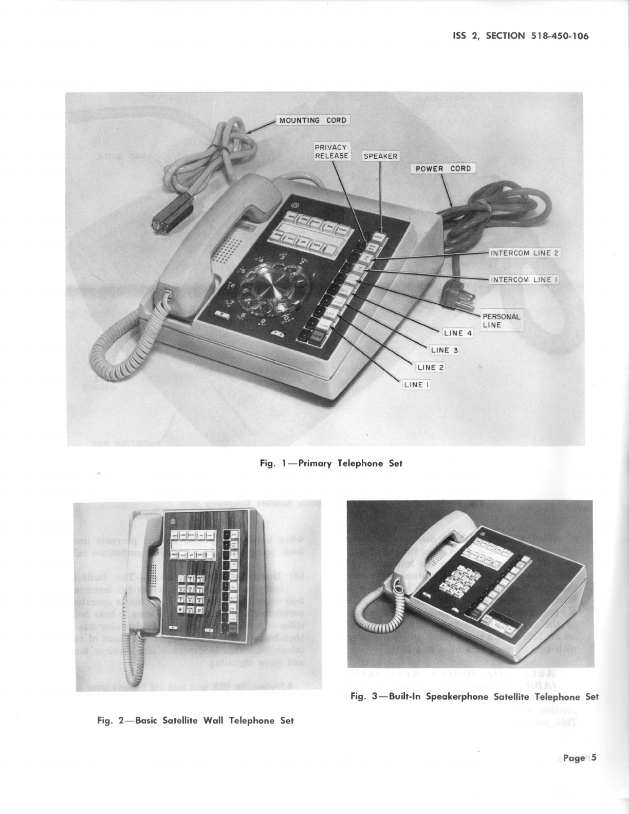
The
system includes five types
of
telephones: (1)
primary sets, (2) basic satellite desk sets, (3) basic
satellite wall sets, (4) satellite sets with built-in
speakerphone (BIS), and (5) satellite sets with
hands-free answering on intercom
(HF
AI). Each
primary.
set
contains
the
control circuitry for two
CO/PBX lines and one intercom
path
and
the
power circuitry to serve itself and some combination
of up to seven satellite sets. The addition of a
second primary
set
doubles
the
capacity of
the
system; up
to
seven more satellite sets can be
connected, with each station in
the
system now
ISS
2,
SECTION
518-450-106
served by up to four CO/PBX lines
and
two intercom
paths. The satellite sets provide
the
same basic
services
as
the primary sets,
but
they do not
contain control and power circuits.
1.04
Because
the
control and power circuitry of
the
4A
System is contained in the primary
station sets,
there
is no need for separately mounted
key service units such
as
most key systems require.
The only equipment required in addition
to
the
telephone sets
are
interconnecting cables, blocks,
adapters, and small externally mounted units for
some optionalfeatures. Systems with many optional
features may require an externally mounted power
unit.
1.05
Each
4A
station can be programmed by,
the
customer to
ring
on
any
combination of
the
common CO/PBX lines. All stations have access
to all common lines in
the
system; therefore, any
set
can be assigned
as
the
attendant
station,
if
one is required. Each station also
has
direct access
to
the
ten intercom codes.
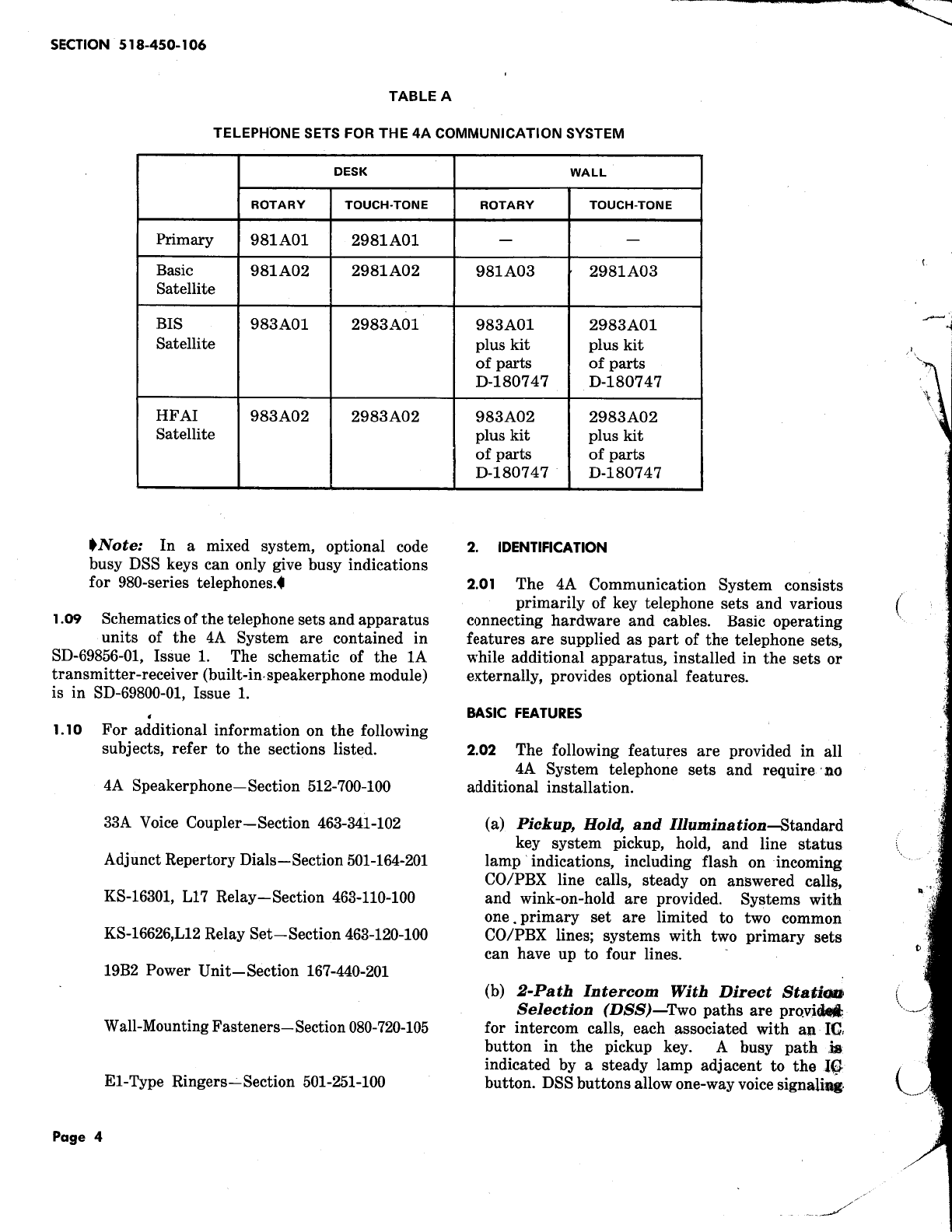
1.06
All
4A
telephone sets
are
available with
either
rotary
or
TOUCH-TONE® dialing.
The
primary
set is available only in a desk-type
model,
but
the
basic satellite sets can be ordered
in both desk and wall configurations.
~.
BIS
and
HF
AI sets
are
convertible from desk'(i(;'wall
mounting by means of a
kit
of
parts.
' ..,
'are
a
total
of
ten
telephone
set
codes in
the
9·
eries
(Table
A).
Fig. 1 through 5
illustrate
tyt)i¥1
sets.
..
1.07
The 4A System derives
its
ac power. from a
standard
117-volt 60-Hz source: The system
components
are
protected by a self-resetting
thermal
cutout in
the
power supply of
the
primary
station,
making separate fusing unnecessary
..
The
19B2
power unit, used when supplementary
de
power is
required,
has
both input and output
fusi~.
1.08
While
the
980-series telephones provide more
optional features
than
the
830-serjes used
with
the
earlier 4A System (Section
518'-Mo-105),
the
two series
are
compatible and interchangeable.
They can coexist in
the
same system, and
~-series
sets can be used to replace 830-seriea' .
sets
in
existing installations. However,
if
supplementary
power is required,
the
primary
sets
must
be from
the 980-series.