SE
CT
ION
C3
8.
670
.
40
TO
55A
CONTROL
UNIT
Page 8
8 Pages
INSIDE
WIRING
GRD
(Y)
CONN MTG
TERM.
BLOCK CORD STRIP SWITCH
ASSEMBLY
CLOSE
FOR
NIGHT
LIGHT
DIAL
SA
NETWORK
495A
[ .
'"
DIAL
LAMP
Rl
A
OR
AG
6
(R)
(BL)
MIW
CORD
(S-
BR)
c
TO
CO
PBX
lA
,I
AI
,
'0----('-c
S
_--:-Y_)
---<~
b
(S)
a(S
-
W)
D
OR
6A
TIP
LINE
(S-RI
(W)
TO c 7 (W)
XMTR
---~~--~~-~
f
(S-BK)
g~~~~-----------------------~
(
W)
UNIT
(G)
e
~T~'-----~~-~(G~)---L~I---(~S_-~G~)~d
2
~
R
~
E
~
A
To
prevent
false
holding
condition
when
handset
is restored,
switch
contacts
cb
must
break
before
de breaks.
D
JL
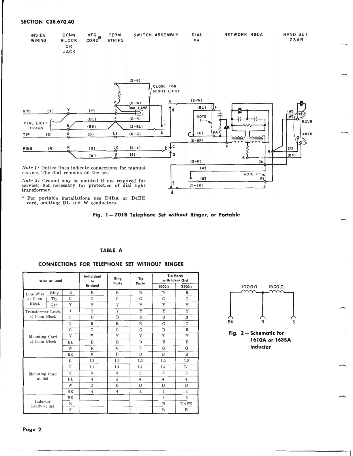
Note
I:
Dotted
lines
indicate
connections
for
manual
service.
The
dial
remains
on
the
set.
Note
2:
Ground
may
be
omitted
if
not
required
for
service;
not
necessary
for
protection
of
dial
light
transformer.
···
Connect
with
D-161488
connector.
Fig.
7-
701 B Telephone
Set
Wired
for
3A
Speakerphone
TABLE
F
7018
MODIFICATION
TELEPHONE
SET
FOR
3A
SPEAKER
·PHONE
Lead From
To
BL
Mtg
Cd 4 D Conn (S-BR)
(S-BR)
Swhk
c
BL
Mtg
Cd D Conn
R
Mtg
Cd L2 F
(S-W) F c
Note:
Strap
3 to L2
term.
strip.
HAND
SET
G3A
R
,