Belle Foret 873W-3501 Assembly instructions
THANK YOU
INSTALLATION AND CARE GUIDE
SINGLE-HANDLE TUB AND SHOWER FAUCET
We appreciate the trust and condence you have placed in Pegasus through the purchase of this tub and
shower faucet. We strive to continually create quality products designed to enhance your home. Visit us online
to see our full line of products available for your home improvement needs. Thank you for choosing Pegasus!
Model#
873W-3501
873W-3504
873W-3527H2
SKU#
724623
724622
718732
YOW 4/2016 REV.01
Questions, problems, missing parts?
Call Belle Forêt Customer Service
8 a.m. - 7 p.m., EST, Monday - Friday
9 a.m. - 6 p.m., EST, Saturday
(800) 880-8164

2
Table of Contents
Important Information..............................2
Warranty ...................................................2
Pre-Installation.........................................3
Planning Installation ..............................3
Package Contents..................................6
Installation................................................7
Care and Cleaning ....................................14
Troubleshooting........................................15
Service Parts
...........................................
16
Important Information
□ Do not install this product until you read and understand the instructions in this manual. If you are installing this
product for someone else, leave this manual for the owner’s/ user’s reference.
□ Inlet ports are designed to allow for 1/2 in. COPPER tubing solder connection or 1/2 in. IPS threading coupling
connection. For threaded connections, wrap sealant tape around threaded ends before connecting. If soldering
connections, certain inammable parts should be removed prior to the soldering in order to avoid heat damage.
If you are unsure how to properly remove these parts, please call us at 1-855-HD-Glacier.
□ Protect your eyes with safety glasses when cutting or soldering water supply lines.
□ NOISE AND WATER HAMMER IN PEX SYSTEMS: Due to the inherent exibility of PEX compared with metallic
plumbing materials, water hammer and noise can sometimes occur from the pressure surges. It is important to
ensure the tubing is not in contact with wallboard, forced air ducts or other high-resonance materials. Clamping
or strapping can help prevent these noises. DO NOT USE PEX tubing from the valve to the tub spout.
Tools and Hardware Required ...............3
Warranty
LIMITED LIFETIME WARRANTY
Belle Forêt products are manufactured with superior quality standards and workmanship and are backed by our
limited lifetime warranty. Belle Forêt products are warranted to the original consumer purchaser to be free of
defects in materials or workmanship. We will replace FREE OF CHARGE any product or parts that prove defective.
Simply, call (800) 880-8164 to receive the replacement item. Proof of purchase (original sales receipt) from the
original consumer purchaser must be made available for all Belle Forêt warranty claims.
This warranty excludes incidental/inconsequential damages and failures due to misuse, abuse or normal wear and
tear. This warranty excludes all industrial, commercial & business usage, whose purchasers are hereby, extended
duration of warranty.
Some states and provinces do not allow the exclusion or limitation of incidental or consequential damages, so the
above limitations may not apply to you. This warranty gives you specic legal rights and you may also have other
rights that vary from state to state and province to province. Please contact (800) 880-8164 for more details.

3
Safety
goggles
Thread
sealant tape
Tube
cutter
Strap wrench
Adjustable
wrench
Measuring
tape Thermometer
Phillips
screwdriver
Flathead
screwdriver
SILICONE
Silicone
sealant
Pre-Installation
PLANNING INSTALLATION
Before beginning the installation of this product, ensure all parts are present. Compare parts with the Package
Contents list. If any part is missing or damaged, do not attempt to install the product. Contact customer service
for replacement parts.
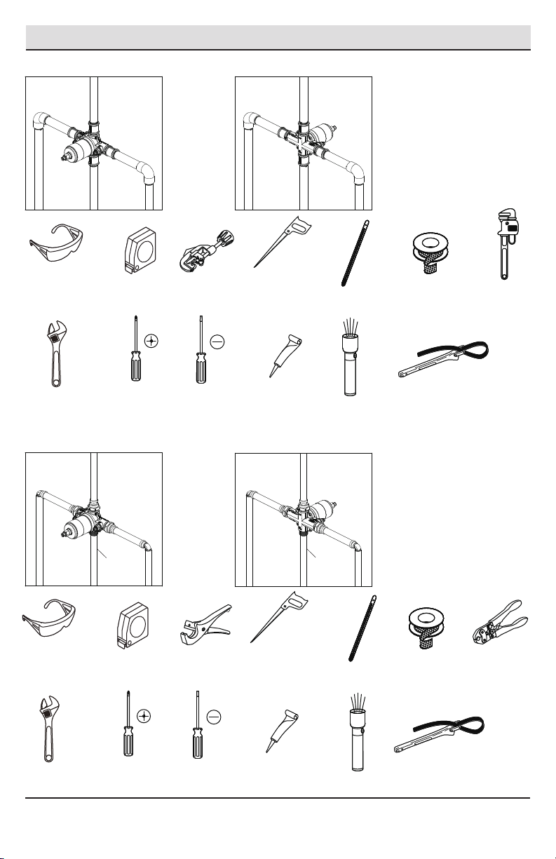
TOOLS AND HARDWARE REQUIRED
ADVANCED INSTALLATION: Consult a plumber or
professional before installing this product.
If you are replacing your plumbing valve, please review the four common plumbing methods illustrated below:
COPPER, IPS, PEX and CPVC. Remove the existing handle and valve trim before replacing your valve. Please follow
all local building and plumbing codes.
A. COPPER (Before soldering, remove the cartridge & stop valves from the valve)
Torch Lead-free solder Kit
Key
hole saw
Wire
brush
All installations can vary depending on how your previous faucet was installed. Not all supplies for faucet
installation are included; however, they are available wherever plumbing supplies are sold. When choosing your
installation supplies, make sure they are UPC and/or CSA approved products.
Flashlight
Please contact (800) 880-8164 for further assistance.
Pre-Installation (continued)
4
Safety
goggles
Thread
sealant tape
Tube
cutter
Strap wrench
Adjustable
wrench
Measuring
tape Thermometer
Phillips
screwdriver
Flathead
screwdriver
SILICONE
Silicone
sealant
B. IPS
Key
hole saw
Flashlight
C. PEX+COPPER
Safety
goggles
Thread
sealant tape
Tube
cutter
Strap wrench
Adjustable
wrench
Measuring
tape Thermometer
Phillips
screwdriver
Flathead
screwdriver
SILICONE
Silicone
sealant
Key
hole saw
Flashlight
Full circle
crimping tool
Pipe
wrench
COPPER COPPER

Pre-Installation (continued)
5
D. CPVC+COPPER
Safety
goggles
Thread
sealant tape
Tube
cutter
Strap wrench
Adjustable
wrench
Measuring
tape Thermometer
Phillips
screwdriver
Flathead
screwdriver
SILICONE
Silicone
sealant
Key
hole saw Flashlight
CPVC
cleaner
P
i
p
e
J
o
i
n
t
C
o
m
p
o
u
n
d
CPVC
cement
P
i
p
e
J
o
i
n
t
C
o
m
p
o
u
n
d
COPPER COPPER
Please contact (800) 880-8164 for further assistance.
6
Pre-Installation (continued)
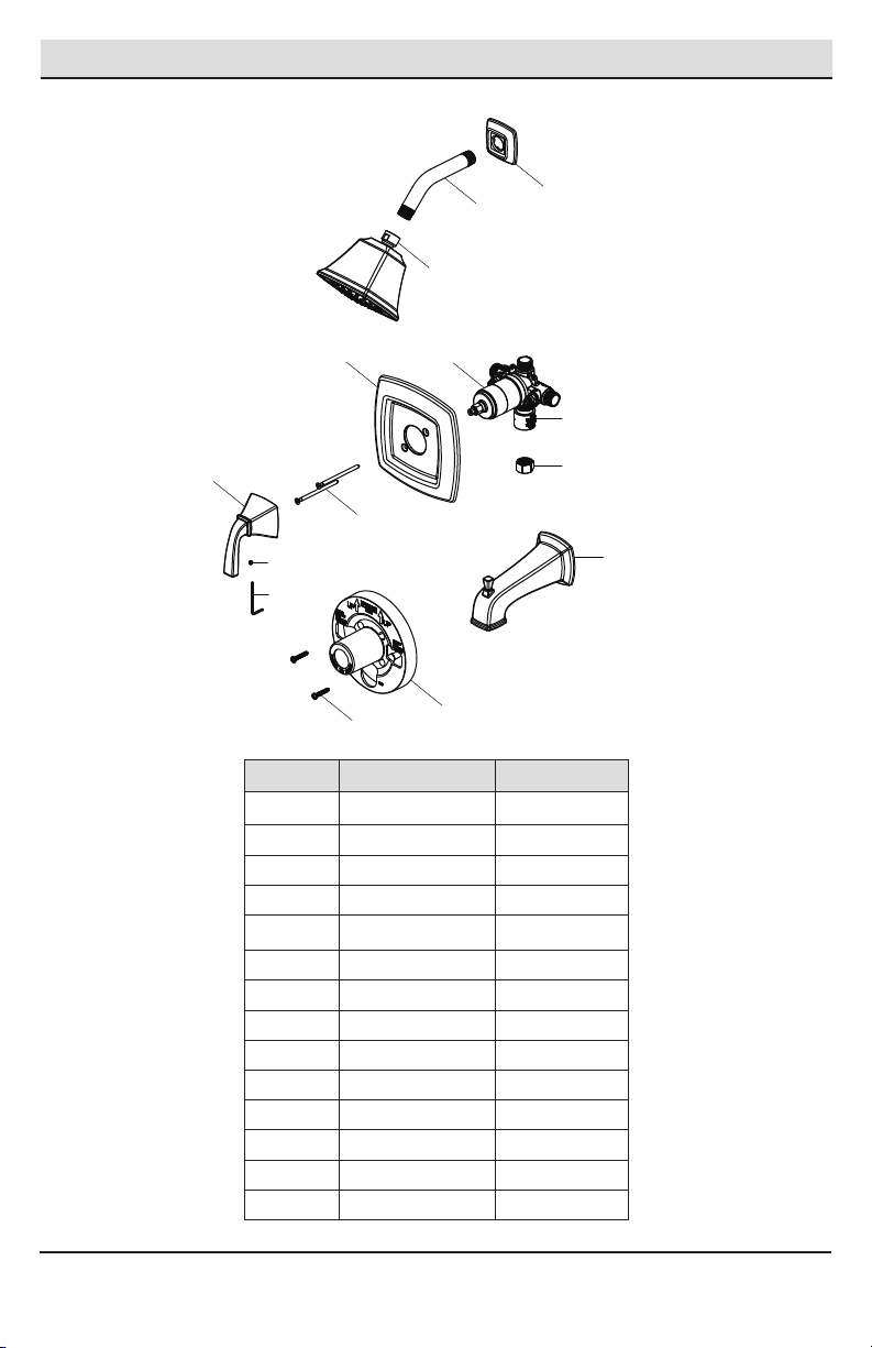
PACKAGE CONTENTS
Part Description Quantity
A1
B Shower arm 1
C Shower head 1
D Valve body 1
E Escutcheon 1
F Handle 1
G Set screw 1
H Hex wrench 1
Shower ange
I Plug 1
J Tub spout 1
K Screw 2
L Plaster guard 1
M Escutcheon screw 2
N Protective cap 1
L
K
A
B
C
DE
FI
J
N
M
G
H

7
Installation
1 Preparing for installation
CAUTION: Always turn off the water supply before
removing an existing faucet or replacing any part of a
faucet. Open the faucet handle to relieve water pressure
and ensure that the water is completely shut off.
30 in.
Tub & Shower
8 in. Min.
48 in.
Shower Only
1 1/4 in. Diamter
1 1/4 in.Diameter
48 in.
Tub & Shower
Refer to
the step 2
30 in.
Shower Only
D
2
1-1/2 in. to 2-1/2 in.
Finished wall
6 in. dia.
D
3-3/8 in. to 6 in. dia.
Finished wall
D
LL
Installing the valve body and
removing the plaster guard
□Shut off the water supply to the tub and
shower.
□Verify that the hole sizes and positions of the
holes in the wall are correct:
□The shower and tub spout outlet holes
should be 1-1/4 in. diameter.
□Refer to Step 2 for valve access hole
dimensions.
□The recommended valve depth to the
nished wall is 2 in. min. to 2-1/2 in. max.
□Ensure that the valve body (D) cover is ush
with the nished exterior surface of the wall.
Position the valve body (D) correctly in the
wall with the side marked "UP" pointing up. The
8 in. minimum from the valve body (D) to the tub
spout (J) is required for proper operation.
A. Thin Wall Installation
“Thin Walls” are usually built up with materials
such as berglass tub surrounding them and will
be the main source of support for the valve. The
plaster guard (L) remains attached to the valve.
□
B. Thick Wall Installation
“Thick Walls” are usually built up with materials such
as cement board, drywall, tile, etc. The plaster guard
(L) is positioned so that it is ush with the nished
wall. This ensures that the valve will be at the correct
position to accept the trim. The depth for the valve
body (D) in wall is measured from the center of the
shower outlet to the nished wall surface. The
accepted depth distance is 1-1/2 in. to 2-1/2 in.. When
the depth distance is 1-1/2 in. to 2 in., there will be
interference between the plaster guard (L) and
escutcheon (E). It is recommended that you remove
the plaster guard (L) after the wall installation.
□
Unscrew the screws (K), and remove the plaster
guard (L).
□
NOTE: Be sure to position the valve body (D) correctly in
the wall, with the side marked "UP" facing upward.
L
K
Please contact (800) 880-8164 for further assistance.
8
Installation (continued)
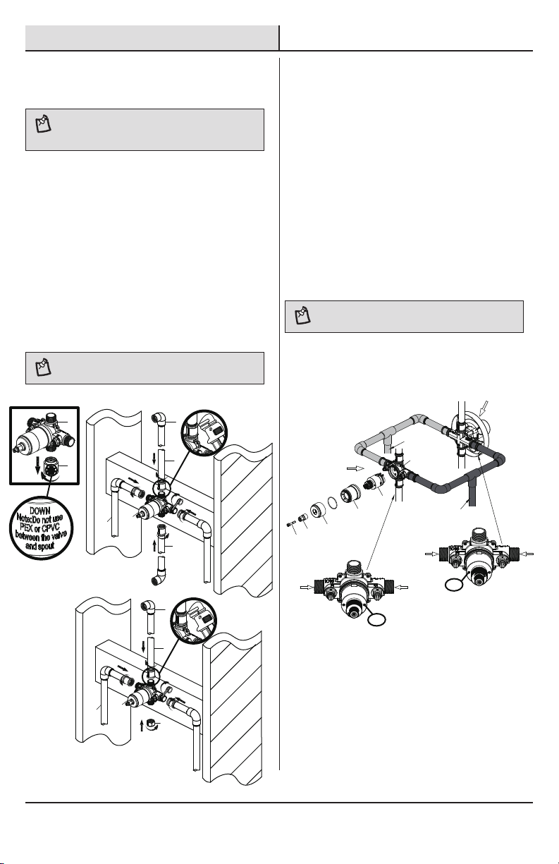
3 Installing the supply
connections
□
□Tighten the pipes to the valve body (D) with a
pipe wrench (not included).
Wrap thread sealant tape (not included) around
the pipe threads in a clockwise direction, as
shown.
□
Connect the hot and cold water supply lines (1,
not included), the shower outlet pipe (2, not
included), and tub outlet pipe (3, not included)
by threading them into the valve body (D) in a
clockwise direction.
Connect the pipe elbows (4, not included) to
the end of the shower outlet and tub outlet
pipes.
□
NOTE: The hot water supply lines go into the "H" inlet, and
the cold water supply lines go into the "C" inlet. Do not use
PEX or CPVC between the valve body (D) and tub spout (J).
NOTE: If you do not wish to install the tub outlet, insert
the plug (I) into the bottom of the valve body (D).
4Back to back installation
NOTE: Never install the valve body (D) upside down!
D
N
3
2
D
1
4
I
2
D
1
4
□If the hot and cold inlets are reversed (hot on
right and cold on left), remove the screw (1),
inverter (2), sleeve (3), and bonnet (4) from the
valve body (D) with reversed supply connections.
Rotate the cartridge (5) 180°, so H appears on
the right. Install the cartridge making sure that
the key is fully engaged with the slot in the
valve body (D). Slide the bonnet (4) over the
cartridge (5) and thread them onto the valve
body (D). Hand tighten securely. Reassemble
the sleeve (3), inverter (2) and screw (1). If you
are not making a reverse or back to back
installation, skip this step and continue with
the step 5.
Cold
Hot
Normal
installation
(changes
not required)
Reverse
installation
Normal installation
Reverse installation
D
123
45
H
Hot
Hot
Cold
Cold H

9
Installation (continued)
6 Installing the plaster guard
Place the plaster guard (L) onto the valve body (D)
and secure with the screws (K).
□
5Flushing the water outlets
□
and checking for leaks
Place the handle (F) on the valve body (D)
inverter and turn the handle (F) to the full on
mixed position. Turn on the hot and cold water
supply lines and allow the water to ow from
the outlets for one minute, or until all foreign
matter has been ushed out. Check for leaks.
Shut off the water at the faucet and supply
lines. Remove the handle (F).
□
NOTE: Be sure to position the plaster guard (L) correctly
onto the valve body (D), with the side marked "SHOWER"
facing upward.
D
K
L
F
D
Please contact (800) 880-8164 for further assistance.
10
Installation (continued)
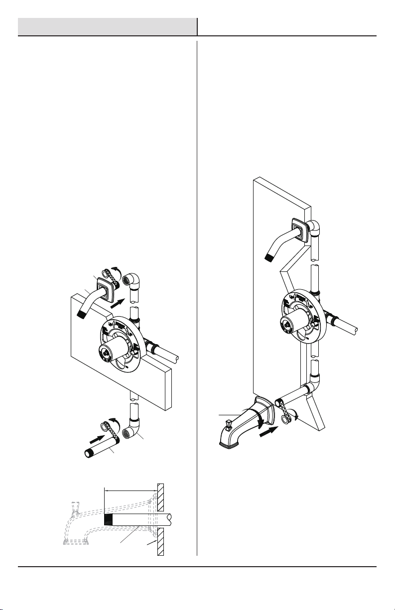
7 Installing the shower arm
□Insert the long end of the shower arm (B) through
the shower ange (A), and wrap thread sealant
tape (not included) around the long end of the
shower arm (B) in a clockwise direction, as
shown.
Install the long end of the shower arm (B)
into the pipe elbow inside the wall. Carefully
tighten the shower arm (B) with a clean strap
wrench. Do not over tighten.
□
Wrap thread sealant tape around the pipe
threads of the tub spout outlet (1, not included)
in a clockwise direction, as shown.
□
Connect the tub spout outlet pipe (the tub
spout outlet pipe should project 3-27/32 in. to
4 in. from the nished wall) to the lower pipe
elbow (2, not included). Tighten the elbow and
tub spout outlet pipe connections with a strap
wrench.
□
8 Installing the tub spout
□
□
Wrap thread sealant tape around the pipe
threads of the tub spout (J) outlet in a clockwise
direction, as shown.
Thread the tub spout (J) onto the threaded
connection in a clockwise direction until the tub
spout (J) becomes ush with the nished wall.
□
Use the strap wrench to tighten the tub spout (J).
3-27/32 in. to 4 in.
Wall
1
1
2
B
A
J

11
Installation (continued)
□Unscrew the sleeve (1) from the valve body (D).
□Unscrew the screw (2) from the inverter (3),
and then remove the inverter (3) from the
valve body (D).
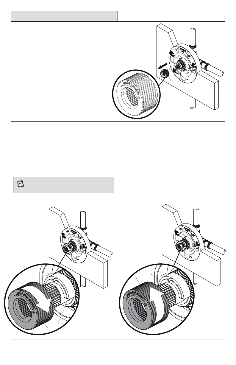
10 Adjusting the temperature
9 Removing the plastic cap
□Before installing the escutcheon (E), remove the
plastic cap (1) from the valve body (D) by twisting
the cap in a clockwise direction when the depth
distance (which is measured from the center of
the shower outlet to the nished wall surface) is
2 in. to 2-1/2 in.. Or unscrew the screws (K) and
remove the plaster guard (L) when the depth
distance (which is measured from the center of
the shower outlet to the nished wall surface)
is 1-1/2 in. to 2 in..
NOTE: The limiter on the valve can be set to allow partial
or full access to hot water by limiting how far the handle
can be turned to the hot side of the valve. The limiter is
typically set at the factory to allow only warm water to pass
through the valve. Follow the directions in this section if you
wish to adjust the amount of hot water that is allowed
through the valve. If you do not wish to adjust the amount
of hot water that is allowed through the valve, proceed to
the step 11, and skip over the step 10 (A, B, C).
ARemoving the sleeve and
inverter
OR
1
D
K
L
D
D
3
12
Please contact (800) 880-8164 for further assistance.
12
Installation (continued)
10 Adjusting the temperature
C Adjusting the desired maximum
water temperature
□For colder water, adjust the red limit stop ring (1) in a clockwise direction and reinstall the red limit stop
ring (1) onto the cartridge assembly (2).
□For hotter water, adjust the red limit stop ring (1) in a counterclockwise direction and reinstall the red
limit stop ring (1) onto the cartridge assembly (2).
B Removing the red limit stop ring
□Remember the position of the red limit stop ring (1)
on the cartridge assembly (2). Remove the red limit
stop ring (1) from the cartridge assembly (2).
NOTE: A thermometer (not included) can be held in the
running water to aid in reaching the desired water
temperature.
For hotter water
For colder water
12
1
2
1
2

Installation (continued)
10 Adjusting the temperature
13
D Reinstalling the inverter and
sleeve
□Place the inverter (2) onto the valve body (D)
and rotate the inverter (2) with notch facing
down. Then secure with the screw (3).
□Screw the sleeve (4) onto the valve body (D).
NOTE: Rotate the cartridge stem (1) clockwise to turn off
the water before you install the handle.
11 Installing the escutcheon
and handle
□Install the escutcheon (E) onto the valve body
(D) using the escutcheon screws (M).
Place the handle (F) onto the valve body (D) and
tighten the set screw (G) with the Hex wrench
(Hex: 2.5 mm, H) provided.
□
D
2
43
1
D
E
M
F
G
H
Please contact (800) 880-8164 for further assistance.

Installation (continued)
13 Installing the shower head
□Attach the shower head (C) to the shower arm
(B). Carefully tighten the shower head (C) with
a clean strap wrench.
12
Checking for leaks
□
□
Turn the handle (F) to the full on mixed position.
When the valve body (D) is turned on, water
normally ows through the tub spout (J). To
activate the shower, turn the valve on and pull
the knob (1) up. Hold the knob (1) until the water
ows continuously from the shower arm (B).
Check for leaks.
Shut off the water at the faucet and supply lines.□
14
Care and Cleaning
□To clean, wipe down with a damp cloth and dry with a towel.
□Do not use abrasive cleaners, steel wool, or harsh chemicals when cleaning this faucet, or the warranty will
be voided.
FOR
UP
SHOWER
1
J
D
F
J
B
B
C

15
Troubleshooting
NOTE: Refer to the Service Parts section in this manual
for a detailed drawing showing the location of the parts
listed below.
Problem Possible Cause Solution
Hot and cold are reversed. The lines are reversed or the cartridge is
installed upside down.
□Rotate the cartridge stem 180°
so that the notch is facing down
towards the drain.
There is no ow or a low
water ow.
□Turn both water supply valves
counterclockwise to the on
position.
There is leaking or dripping
from the spout when the
handle is closed.
The grommets are not sealing properly. □Replace the cartridge.
One or both water supplies are not turned
on.
Water comes out of the
tub spout and showerhead
at the same time.
If the pattern of the water ow switches to
the shower from the tub spout, and the leak
from the tub spout is less than 0.01 GPM,
this is a normal occurrence. Or consider the
causes below:
! The pipe used between the valve and the
tub spout is not 1/2 in. IPS, or the COPPER
pipe is incorrect.
! The distance between the valve and the
showerhead is less than 48 in..
! There is a restriction between the valve
and the tub spout.
! The valve is installed upside down.
□Change the pipe to IPS or
COPPER.
□The distance from the
showerhead and valve moved
to at least 48 in..
□Remove the tub spout and ush
out debris and/or replace the
undersized line or ttings.
□Remove the valve and reinstall it
using the correct orientation.
The temperature range is
restricted.
The temperature limit stop is out of position. □Refer to the section Adjusting
the Temperature.
The handle cannot be
installed or the handle rubs
against the escutcheon.
The valve is installed too far back from the
nished wall.
□Reinstall the valve (refer to Step
2 of the Installation section).
The handle is hard to turn. The bonnet nut is too tight. □Loosen the bonnet nut and
reinstall it. Do not overtighten.
Please contact (800) 880-8164 for further assistance.

16
Part Description Part Number
1 RP38286*
2 Shower arm RP38019*
3 Shower head RP38287*
4 O-ring RP60101
5 Cartridge RP20075
6 O-ring RP60091
7 Bonnet RP70437*
8 Sleeve RP80297*
9 Inverter RP64043
Shower ange
Part Description Part Number
10 Screw RP50020
11 Escutcheon RP80535*
12 Escutcheon screw RP50066*
13 Handle RP13453*
14 Set screw RP50002
15 Plug RP70365
16 Spout RP33072*
Service Parts
*Specify Finish
Faucet ID tags can be
found by removing the
handle
14
13
12
11 10
9
87
6
54
15
16
2
1
3

Questions, problems, missing parts?
Call Belle Forêt Customer Service
8 a.m. - 7 p.m., EST, Monday - Friday
9 a.m. - 6 p.m., EST, Saturday
(800) 880-8164
Retain this manual for future use.

GUÍA DE USO Y MANTENIMIENTO
GRIFO PARA BAÑERA Y DUCHA, DE UNA SOLA LLAVE
Apreciamos la conanza que has depositado en Pegasus al comprar este grifo para bañera y ducha. Nos esforzamos
por crear continuamente productos de calidad diseñados para mejorar tu hogar. Visítanos en Internet para ver
nuestra línea completa de productos disponibles para las necesidades de mejoras de tu hogar.
¡Gracias por elegir a Pegasus!
GRACIAS
Modelo núm.
873W-3501
873W-3504
873W-3527H2
SKU núm.
724623
724622
718732
¿Problemas, preguntas o piezas faltantes?
Llama al servicio al cliente de Belle Forêt
de lunes a viernes entre 8 a.m. y 7 p.m. y los
sábados entre 9 a.m. y 6 p.m.(hora estándar del Este)
(800) 880-8164

19
Tabla de contenido
Información importante .........................19
Garantía...................................................19
Pre-instalación .......................................20
.............20
Herramientas y herrajes necesarios....20
Contenido del paquete.........................23
Instalación ..............................................24
Planicación de la instalación
Cuidado y limpieza ................................31
Piezas de repuesto ................................33
Solución de problemas...........................32
Información importante
□ No instales este producto hasta que hayas leído y entendido las instrucciones de este manual. Si estás instalando
este producto para alguien, déjale este manual para que le sirva como referencia al dueño/usuario.
□ Los puertos de entrada están diseñados para 1/2 plg. Conexión de soldadura de tubería de COBRE o 1/2 plg.
Conexión de acoplamiento de rosca IPS. Para conexiones roscadas, envuelve los extremos roscados con cinta
selladora antes de conectar. Si vas a soldar las conexiones, algunas partes inamables deben quitarse antes
de la soldadura para evitar daños por calor. Si no estás seguro sobre cómo quitar estas partes, llámanos a
1-855-HD-Glacier.
□ Al soldar o cortar las líneas de suministro de agua, protege tus ojos con gafas de seguridad.
□ RUIDO Y GOLPE DE ARIETE EN SISTEMAS PEX: Debido a la exibilidad inherente del PEX, en comparación con
materiales de plomería metálicos, el ruido y golpe de ariete puede ocurrir de vez en cuando por sobrecargas
de presión. Es importante garantizar que la tubería no esté en contacto con paneles de pared, ductos de aire
propulsado u otros materiales de alta resonancia. La sujeción o anclaje son métodos para evitar estos ruidos.
NO USES tuberías PEX desde la válvula al caño de la bañera.
Garantía
GARANTÍA LIMITADA DE POR VIDA
Los productos de Belle Forêt están fabricados con normas y mano de obra de calidad superior y están respaldados
por nuestra garantía de por vida limitada. Belle Forêt garantiza al comprador consumidor original que sus
productos no presentan defectos materiales o de fabricación. Reemplazaremos GRATIS cualquier producto o pieza
defectuosos. Simplemente llama al (800) 880-8164 para recibir el artículo de reemplazo. El comprobante de
compra (recibo de venta original) del comprador consumidor original debe estar disponible para todos los
reclamos de garantía de Belle Forêt.
Esta garantía excluye daños y fallos incidentales/consecuenciales debido al mal uso, abuso o desgaste normal
por el uso. Esta garantía excluye todos los usos industriales, comerciales y de negocios, a cuyos compradores
se les extiende en la presente una garantía limitada de cinco años a partir de la fecha de compra, con todos
los otros artículos de esta garantía que aplican excepto la duración de la garantía.
Algunos estados y provincias no permiten la exclusión o la limitación de los daños incidentales o consecuentes,
por lo tanto, las limitaciones y exclusiones anteriores podrían no aplicarse a su caso. Esta garantía le otorga
derechos legales especícos y también puede tener otros derechos que varían de un estado a otro. Para obtener
más detalles, comunícate con el (800) 880-8164.

20
Pre-instalación
PLANIFICACIÓN DE LA INSTALACIÓN
Gafas de
seguridad
Cinta selladora
para roscas
Cortador de
tuberías
Llave de correa
Llave
ajustable
Cinta
métrica Termómetro
Destornillador
Phillips
Destornillador de
cabeza plana
SILICONE
Sellador de
silicona
Antes de comenzar la instalación de este producto, asegúrate de que no falta ninguna pieza. Compara las piezas
con la lista de Contenido del paquete. Si falta alguna pieza o está dañada, no intentes instalar el producto.
Comunícate con el servicio al cliente para piezas de repuesto.
HERRAMIENTAS Y HERRAJES NECESARIOS
INSTALACIÓN AVANZADA: Consulta a un plomero o
profesional antes de instalar este producto.
Si estás cambiando tu válvula de plomería, consulta los cuatro métodos comunes que aparecen más abajo: COBRE,
IPS, PEX y CPVC. Quita la manija y el regulador de válvula preexistentes antes de reemplazar tu válvula. Cumple con
todos los códigos locales de construcción y plomería.
A. COBRE (Antes de soldar, quita el cartucho y las válvulas de cierre del cuerpo de la válvula)
Soplete Kit de alambre de
soldadura sin plomo
Serrucho
de punta
Cepillo de
alambre
Todas las instalaciones pueden variar en dependencia de cómo estaba instalado el grifo anterior. No se incluyen todos
los suministros para la instalación del grifo; sin embargo, están disponibles dondequiera que se vendan suministros de
plomería. Al elegir tus suministros de instalación, asegúrate de que son productos aprobados por UPC y/o CSA.
Linterna
Para obtener asistencia, llama al (800) 880-8164.
This manual suits for next models
5
Table of contents
Languages:
Popular Bathroom Fixture manuals by other brands


Kohler
Kohler K-3566T-U installation instructions

Kohler
Kohler OVE Vanity Lavatory K-19950T installation instructions

Kohler
Kohler K-9694 installation guide

OVE
OVE TAMPA-PRO TP0130 G Series installation manual

Clou
Clou Hammock CL/03.13370 installation instructions

Fleurco
Fleurco Platinum Cube PLAQ3660-11-40L-MA-79 instruction manual


