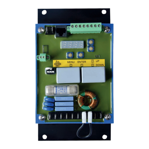
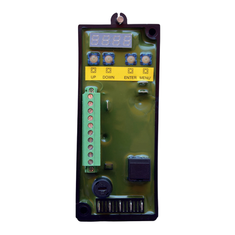
Beltrame S2006 User manual


2/67
Index
Index ...........................................................................................................................................2
Important Notice ..........................................................................................................................4
1. Safety instructions ............................................................................................................5
1.1 General .................................................................................................................................. 5
1.2 Safety Instructions..................................................................................................................6
2. Product description...........................................................................................................7
2.1 Preface...................................................................................................................................7
2.2 Area of application..................................................................................................................8
2.3 Hardware................................................................................................................................9
2.3.1 Control elements and interfaces ...............................................................................10
2.3.2 Device connections: power and high voltage ............................................................13
2.3.3 Device connections: control signals and interfaces...................................................14
3. Operator interface ...........................................................................................................18
3.1 Control keyboard and signaling............................................................................................18
3.2 Navigating the menus........................................................................................................... 19
3.3 Display ................................................................................................................................. 21
3.3.1 Field .........................................................................................................................21
3.3.2 Generator.................................................................................................................21
3.3.3 Mains........................................................................................................................21
3.3.4 Actual regulation.......................................................................................................22
3.3.5 Digital & Analog Inputs/Outputs monitor....................................................................22
3.3.6 Fieldbus....................................................................................................................23
3.3.7 Alarms......................................................................................................................23
3.3.8 Fault log details ........................................................................................................23
3.3.9 Exciter......................................................................................................................24
4. Configuration...................................................................................................................25
4.1 Inputs and outputs................................................................................................................25
4.1.1 Digital inputs.............................................................................................................25
4.1.2 Enabling virtual digital inputs.....................................................................................26
4.1.3 Digital outputs...........................................................................................................27
4.1.4 Enabling virtual digital outputs ..................................................................................28
4.1.5 Fast De-Excitation output..........................................................................................29
4.1.6 Analog inputs............................................................................................................31
4.1.7 Enabling virtual analog inputs...................................................................................33
4.1.1 Analog Outputs.........................................................................................................34
4.1.1 Enable Virtual Analog Outputs..................................................................................36
4.1.1 RS485 Communication.............................................................................................37
4.1.1 USB Communication ................................................................................................37
4.1.1 CAN bus communication ..........................................................................................37
4.1.1 Ethernet communication...........................................................................................38
4.2 Description and Configuration Parameters...........................................................................38
4.2.1 Field excitation data..................................................................................................38
4.2.1 Minimum Excitation Current......................................................................................38
4.2.1 Maximum Excitation Current.....................................................................................39
4.2.2 Generator data .........................................................................................................39
4.2.3 Generator current .....................................................................................................40
4.2.1 V/Hz limit..................................................................................................................40
4.2.2 Soft Start ..................................................................................................................41
4.2.1 The Limit of Minimum Reactive Power......................................................................41
4.2.1 The Limit of Maximum Reactive Power.....................................................................42
4.2.1 Implementation Limits...............................................................................................42
4.2.2 Sensing....................................................................................................................43
4.2.3 Power supply............................................................................................................43
4.2.4 Control mode............................................................................................................43

3/67
4.2.5 Droop .......................................................................................................................44
4.2.6 Series compensation................................................................................................44
4.2.7 Field flashing............................................................................................................45
4.2.8 Boost........................................................................................................................45
4.2.9 New Function Q........................................................................................................46
4.2.10 New Function PF......................................................................................................46
4.2.11 Rotor diode monitor..................................................................................................46
4.2.12 Synchronization (optional) ........................................................................................48
4.2.13 Alarms......................................................................................................................49
4.2.14 Limitations................................................................................................................49
4.2.15 Operator interface.....................................................................................................49
4.3 Commands...........................................................................................................................50
4.3.1 Non volatile parameters............................................................................................50
4.3.2 Self commissioning...................................................................................................50
4.3.3 System test utilities...................................................................................................50
4.3.4 Virtual I/O .................................................................................................................50
4.3.5 Alarm........................................................................................................................50
4.3.6 Access control..........................................................................................................51
5. Reference and regulators...............................................................................................52
5.1 PWM reference (PWM)........................................................................................................52
5.2 Field voltage reference (FVR) ..............................................................................................53
5.3 Field current reference and regulator (FCR) ........................................................................ 54
5.4 Generator voltage reference and regulator (AVR)................................................................ 55
5.5 Generator PF reference and regulator (PF) .........................................................................56
5.6 Generator VAR reference and regulator (VAR)....................................................................57
5.7 Limit regulators.....................................................................................................................58
6. Commissioning................................................................................................................59
6.1 Safety regulations................................................................................................................. 59
6.2 Connection of the Regulator................................................................................................. 59
6.2.1 Power Supply ...........................................................................................................59
6.2.1 Voltage Signals.........................................................................................................59
6.3 Setting the Standard Parameters......................................................................................... 59
6.4 Operations to be done while the machine is off....................................................................60
6.5 Operations to be done while the machine is off....................................................................61
7. Maintenance and Breakdown.........................................................................................62
7.1 Maintenance.........................................................................................................................62
7.2 Problem Solving................................................................................................................... 62
8. General data.....................................................................................................................64
8.1 S2006 up to 15A...................................................................................................................65
8.2 S2006 up to 25A...................................................................................................................66
8.3 S2006 up to 40A...................................................................................................................67

4/67
Important Notice
Our experience has shown that, if the information and recommendations contained in this Operating Instructions
are observed, the best possible reliability of our products is assured.
The data contained herein purports solely to describe the product and is not a warranty of performance or
characteristics. It is with the best interests of our customers in mind that we constantly strive to improve our
products and keep them abreast of advances in technology. This may, however, lead to discrepancies between a
product and its "Technical Description" or " Operating Instructions".
This document has been carefully prepared and reviewed, however should in spite of this the reader find an error,
he is requested to inform us at his earliest convenience.
It is scarcely possible for the operating instructions for technical equipment to cover every eventuality, which can
occur in practice. We would therefore request you to notify us or our agent in the case of all unusual behaviour that
does not appear to be covered by these operating instructions.
It is pointed out that all local regulations must be observed when connecting and commissioning this equipment in
addition to these operating instructions.
We cannot accept any responsibility for damage incurred as a result of mishandling the equipment regardless of
whether particular reference is made in these operating instructions or not.
We lay particular stress on the fact that only genuine spare parts should be used for replacements.
All rights with respect to this document, including applications for patent and registration of other industrial property
rights, are reserved. Unauthorized use, in particular reproduction or making available to third parties, is prohibited.

5/67
1. SAFETY INSTRUCTIONS
1.1 General
The safety instructions shall be followed during installation, commissioning, operation and maintenance of the
excitation system. Read all instructions carefully before operating the device and keep this manual for future
reference.
Required Qualification
Personnel involved in installation work and commissioning of the S2006 must be familiar, specially
instructed and informed about the residual danger areas according to the regulations currently in force.
Operating personnel is not permitted to work at the control system.
Specially instructed personnel must only carry out maintenance and repair work.
The maintenance personnel must be informed about the emergency shutdown measures and must be
capable of turning off the system in case of emergency.
The maintenance personnel must be familiar with the accident prevention measures at their workplace
and must be instructed in first aid and fire fighting.
It is the owner’s responsibility to ensure that each person involved in the installation and commissioning
of the S2006 has received the appropriate training or instructions and has thoroughly read and clearly
understood the safety instructions in this chapter.

6/67
1.2 Safety Instructions
The safety instructions always appear at the beginning of each chapter and/or precede any instruction in the
context where a potentially dangerous situation may appear. The safety instructions are divided into five categories
and emphasized by the use of the following layout and safety signs:
DANGER!
This symbol indicates an imminent danger resulting from mechanical forces or
high voltage. A non-observance leads to life-threatening physical injury or death.
WARNING!
This symbol indicates a dangerous situation. A non-observance may lead to bad
or life-threatening physical injury or death.
IMPORTANT!
This symbol indicates useful information. Not to be used to indicate dangerous
situations.
NOTICE!
This symbol emphasizes important information. A non-observance may cause
damage to the converter or to objects close to it.

7/67
2. PRODUCT DESCRIPTION
2.1 Preface
From a consolidated operating experience in the energy sector Beltrame has created a device of high performance:
the S2006 voltage regulator.
S2006 is an automatic voltage regulator of the latest design for synchronous generators and synchronous motors.
The unit contains the most advanced microprocessor technology together with IGBT semiconductor technology
(Insulated Gate Bipolar Transistor).
A practical and simple-to-operate panel on the unit is used for all control operations. In addition, user friendly
software facilitates commissioning and allows optimization of operation.
The mechanical construction is compact and robust. You can order the regulator in the rack configuration 19 ".

8/67
2.2 Area of application
This advanced-design automatic voltage regulator is used for the excitation of indirectly excited synchronous
machines. This unit is only suitable for this one area of application.
The regulator can also be switched over to function as a reactive power-, power factor- or field current regulator.
SM = Synchronous Machine
E = Exciter
PMG = Permanent-Magnet-Generator
Optional:
Synchronization unit
Diode monitoring
Change over to a back-up unit.
Generator or motor excitation with
PMG or external supply.
Replacement of voltage regulators for
generators or motors with direct-current
excitation machines.

9/67
2.3 Hardware
Structure:
The device is built into an aluminum casing with cooling flanges.
The connection terminals are integrated around of the circuit boards.
Power electronics:
The power part is fitted with an IGBT semiconductor.
The average value of the output voltage is always positive.
The output is current limited and short-circuit proof.
Control elements:
The operating keys and the display are located on the unit cover.
Installation:
The site of installation must be dry and free of dust.
Mounting:
The S2006 is designed for wall mounting.
For optimal cooling is to keep free a minimum distance of 100mm all around the unit.
Connection diagram:

10/67
2.3.1 Control elements and interfaces
Carrying out settings on the unit
The display and the four keys are sufficient to allow complete operation.
All settings can be carried out directly on the unit without additional equipment
Configuration of inputs and outputs
Parameter setting
Display of important measuring values.
Interface with PC
Parameter setting and also optimization is possible using the user-friendly software S2006 Configurator
for Microsoft Windows.
Connection cable, standard USB with A-B connectors
Configuration of inputs and outputs
Parameter setting
Trending function for optimization of the controller (Oscilloscope, Power chart)
Display of important measuring values
Parameter File upload or download.

11/67
Terminal blocks
Overview of the device connections

12/67
CN1 –Communication USB (type B)
1. V USB
2. D-
3. D+
4. GND USB
CN2 –Communication CANBUS
1. CAN H
2. CAN H
3. CAN L
4. CAN L
5. GND CAN
6. GND CAN
CN3 –Communication RS485
1. Link-
2. Link-
3. Link+
4. Link+
5. GND RS485
6. GND RS485
CN4 –Analogic inputs/outputs
1. Output +10V (eventual potentiometer)
2. Analog input 1 (-20mA÷+20mA or -10V÷+10V)
3. Analog input 1 GND
4. Output +10V (eventual potentiometer)
5. Analog input 2 (-20mA÷+20mA or -10V÷+10V)
6. Analog input 2 GND
7. Analog output 1 +
8. Analog output 1 GND
9. Analog output 2 +
10. Analog output 2 GND
11. Watch-dog C
12. Watch-dog E
CN13 –Digital outputs
1-2. Digital output K10
3-4. Digital output K9
5-6. Digital output K8
7-8. Digital output K7
9-10. Digital output K6
11-12. Digital output K5
13-14. Digital output K4
15-16. Digital output K3
17-18. Digital output K2
19-20. Digital output K1
CN18 –Digital outputs
1-2. Digital output K16
3-4. Digital output K15
5-6. Digital output K14
7-8. Digital output K13
9-10. Digital output K12
11-12. Digital output K11
CN 20 –Digital inputs
1. Digital input 10
2. Digital input 9
3. Digital input 8
4. Digital input 7
5. Digital input 6
6. Digital input 5
7. Digital input 4
8. Digital input 3
9. Digital input 2
10. Digital input 1
11. + 24V (for PNP connection)
12. GND (for NPN connection)
CN 21 –Digital inputs
1. Digital input 16
2. Digital input 15
3. Digital input 14
4. Digital input 13
5. Digital input 12
6. Digital input 11
CN22 –Sensing inputs
1. TA-S1 generator
2. TA-S2 generator
3. nc
4. L1 generator
5. L2 generator
6. L3 generator
7. L1 main
8. L2 main
CN23 –De-energize command
1. +
2. -
CN 24 –Power electronics supply input
1. Phase L1
2. Phase L2
3. Phase L3
4. P.E.
CN 25 –Excitation output
1. Excitation +
2. Excitation –
CN 30 –Auxiliary power supply (optional)
1. L
2. N
3. P.E.
4. P.E.
nc = not connected

13/67
2.3.2 Device connections: power and high voltage
Terminal designation
Signal
Specifications
Auxiliary supply (optional)
AC input voltage
20 to 265 Vrms 50÷60 Hz
DC input voltage
20 to 400 Vdc
Power electronics supply
AC input voltage
three-phase
Two models are available according
to the maximum supply voltage:
265Vrms / 400Vdc
530Vrms / 800Vdc
AC input voltage
single-phase
DC input voltage
Measurements inputs
3 generator voltage
Galvanic isolation
0÷100 or 0÷500 Vrms
Automatic range selection
2 main voltage
1 generator current
Galvanic isolation
0÷1 or 0÷5 Arms
Automatic range selection
Excitation output
Excitation
0 to Vmax, where Vmax is a function
of the input voltage of the power
electronics supply:
up to 98% of DC supply
up to 90% of rectified AC supply
for three-phase
up to 80% of rectified AC supply
for single-phase
Current: (five sizes available)
0 to 5A
0 to 10A
0 to 15A
0 to 25A
0 to 40A
𝑉
𝑆= 𝑉
𝐸𝑁 *
Ceiling * 0,741

14/67
2.3.3 Device connections: control signals and interfaces
Terminal designation
Signal
Specifications
Digital inputs
16 digital inputs
Connection with internal supply
connection with external supply
opto-isolated
12-24V / 2,5mA
programmable function

15/67
Terminal designation
Signal
Specifications
Digital outputs
16 digital outputs
relay, CO voltage-free contact
6A @ 250Vac
6A @ 30Vdc
0.2A @ 110Vdc
0.1A @ 220Vdc
programmable function

16/67
Terminal designation
Signal
Specifications
Analog inputs
2 analog inputs
opto-isolated
differential input
0÷20mA / -10÷10V by software
setting
programmable function
Analog output
2 analog outputs
opto-isolated
4÷20mA
maximum voltage 20V
Load 47Ω ≤ Rc ≤470Ω
Watchdog
1 digital output
opto-isolated transistor
1mA @ 24Vdc
Communication
1 USB
opto-isolated
standard type “B” connector
Virtual Com Port driver
Modbus RTU and proprietary
protocols

17/67
Terminal designation
Signal
Specifications
1 RS485
opto-isolated
half duplex
multidrop, max 128 devices
selectable termination
Modbus RTU and proprietary
protocols
1 CAN
opto-isolated
selectable termination
CAN open and proprietary protocols
2 Ethernet
(optional)
galvanic isolation
standard RJ-45 connectors
full duplex 10/100Base-TX
Modbus/TCP protocol
RSTP protocol for loop-free
redundant connection

18/67
3. OPERATOR INTERFACE
In this following charter are described the operations of management parameter, using programming keyboard.
3.1 Control keyboard and signaling
The modifications operated on the values of the parameters, also entering in action immediately, are not stored in
way automatic, but require a specific action of storage that is obtained by means of the command “C.000” [Save
parameters].
MScroll menu: Consent change menu’ parameter (d.xxx, R.xxx, I.xxx, P.xxx and C.xxx).
EEnter: used to begin setting parameter and/or confirm value;
UP: used to increase displaying parameter and/or numerical value;
DOWN: used to decrease displaying parameter and/or numerical value;
+ UP + DOWN = RESET
pushed both execute manual reset
K1 K1: the function is freely programmable by parameter
K2 K2: the function is freely programmable by parameter
Meaning of LED :
Run (green Led): - led on = The RUN command is enabled and activated
- led fast blinking = The controller is limiting
Ind (green Led): positive reactive power generated
Cap (green Led): negative reactive power generated

19/67
SW (red Led): - led on = Parallel Switch Closed
- led slow blinking = Operation outside the synchronization window
- led fast blinking = Operation within the synchronization window
Prg (yellow Led): - led on = when not ready to run
- led blinking = when a parameter modification is not saved
L1 (yellow Led): the function is freely programmable by parameter (default = calibrator at minimum)
L2 (yellow Led): the function is freely programmable by parameter (default = calibrator at maximum)
3.2 Navigating the menus
When the S2006 is power on, the display automatically shows parameter d.000 (Field current) in the Display menu.

20/67
Example: how to change the Iecc reference
Example: how to save the parameters after the change
Table of contents
Other Beltrame Controllers manuals
Popular Controllers manuals by other brands

iNels
iNels RFWB-20/G quick start guide
Marshall Excelsior
Marshall Excelsior MEGR-167CH/751 instruction manual

Moons'
Moons' LIN ENGINEERING Silverpak 17C user manual

Ascon tecnologic
Ascon tecnologic TLZ35 operating instructions
Rockwell Automation
Rockwell Automation Allen-Bradley 1512A user manual
ZyXEL Communications
ZyXEL Communications Network Device NXC-8160s quick start guide
